2011 NISSAN TIIDA battery replacement
[x] Cancel search: battery replacementPage 2513 of 3787
![NISSAN TIIDA 2011 Service Repair Manual PRECAUTIONSEM-123
< SERVICE INFORMATION > [MR18DE]
C
D
E
F
G H
I
J
K L
M A
EM
NP
O
5. When the repair work is completed, return the ignition switch to the
″LOCK ″ position before connecting
the b](/manual-img/5/57396/w960_57396-2512.png "NISSAN TIIDA 2011 Service Repair Manual PRECAUTIONSEM-123
< SERVICE INFORMATION > [MR18DE]
C
D
E
F
G H
I
J
K L
M A
EM
NP
O
5. When the repair work is completed, return the ignition switch to the
″LOCK ″ position before connecting
the b")
PRECAUTIONSEM-123
< SERVICE INFORMATION > [MR18DE]
C
D
E
F
G H
I
J
K L
M A
EM
NP
O
5. When the repair work is completed, return the ignition switch to the
″LOCK ″ position before connecting
the battery cables. (At this time, the steering lock mechanism will engage.)
6. Perform a self-diagnosis check of al l control units using CONSULT-III.
Precaution for Procedure without Cowl Top CoverINFOID:0000000005930985
When performing the procedure after removing cowl top cover, cover
the lower end of windshield.
Precaution for Drain CoolantINFOID:0000000005930986
• Drain coolant when engine is cooled.
Precaution for Disconnecting Fuel PipingINFOID:0000000005930987
• Before starting work, make sure no fire or spark producing items are in the work area.
• Release fuel pressure before disassembly.
• After disconnecting pipes, plug openings to stop fuel leakage.
Precaution for Removal and DisassemblyINFOID:0000000005930988
• When instructed to use special service tools, use the spec ified tools. Always be careful to work safely, avoid
forceful or uninstructed operations.
• Exercise maximum care to avoid damage to mating or sliding surfaces.
• Cover openings of engine system with tape or the equiva lent, if necessary, to seal out foreign materials.
• Mark and arrange disassembly parts in an organized way for easy troubleshooting and assembly.
• When loosening nuts and bolts, as a basic rule, start with the one furthest outside, then the one diagonally
opposite, and so on. If the order of loosening is specif ied, do exactly as specified. Power tools may be used
where noted in the step.
Precaution for Inspection, Repair and ReplacementINFOID:0000000005930989
• Before repairing or replacing, thoroughly inspect parts. Inspect new replacement parts in the same way, and
replace if necessary.
Precaution for Assembly and InstallationINFOID:0000000005930990
• Use torque wrench to tighten bolts or nuts to specification.
• When tightening nuts and bolts, as a basic rule, equally tighten in several different steps starting with the ones in center, then ones on inside and outside diagonally in this order. If the order of tightening is specified,
do exactly as specified.
• Replace with new gasket, packing, oil seal or O-ring.
• Thoroughly wash, clean, and air-blow each part. Carefully check oil or coolant passages for any restriction
and blockage.
• Avoid damaging sliding or mating surfaces. Completely remove foreign materials such as cloth lint or dust. Before assembly, oil sliding surfaces well.
• Release air within route after draining coolant.
• Before starting engine, apply fuel pressure to fuel lines with turning ignition switch ON (with engine stopped). Then make sure that there are no leaks at fuel line connections.
• After repairing, start engine and increase engine speed to check coolant, fuel, oil, and exhaust systems for leakage.
PIIB3706J
Revision: May 2010 2011 Versa
Page 3033 of 3787

LT-1
ELECTRICAL
C
DE
F
G H
I
J
L
M
SECTION LT
A
B
LT
N
O P
CONTENTS
LIGHTING SYSTEM
SERVICE INFORMATION .. ..........................3
PRECAUTIONS .............................................. .....3
Precaution for Supplemental Restraint System
(SRS) "AIR BAG" and "SEAT BELT PRE-TEN-
SIONER" ............................................................. ......
3
Precaution Necessary for Steering Wheel Rota-
tion After Battery Disconnect ............................... ......
3
HEADLAMP (FOR USA) .....................................5
Component Parts and Harness Connector Loca-
tion ...................................................................... ......
5
System Description ...................................................5
CAN COMMUNICATION SYSTEM DESCRIP-
TION .................................................................... ......
6
Schematic .................................................................7
Wiring Diagram .........................................................8
Terminal and Reference Value for BCM .................11
Terminal and Reference Value for IPDM E/R .........11
How to Perform Trouble Diagnosis .........................12
Preliminary Check ...................................................12
CONSULT-III Function (BCM) .................................12
CONSULT-III Function (IPDM E/R) .........................13
Headlamp High Beam Does Not Illuminate (Both
Sides) .................................................................. ....
15
Headlamp High Beam Does Not Illuminate (One
Side) .................................................................... ....
17
High Beam Indicator Lamp Does Not Illuminate .....18
Headlamp Low Beam Does Not Illuminate (Both
Sides) .................................................................. ....
19
Headlamp Low Beam Does Not Illuminate (One
Side) .................................................................... ....
21
Headlamps Do Not Turn OFF .................................22
Aiming Adjustment ..................................................23
Bulb Replacement ...................................................24
Removal and Installation .........................................25
Disassembly and Assembly ................................ ....25
HEADLAMP (FOR CANADA) - DAYTIME
LIGHT SYSTEM - ........................................... ....
27
Component Parts and Harness Connector Loca-
tion ....................................................................... ....
27
System Description ..................................................27
CAN Communication System Description ...............29
Schematic ................................................................30
Wiring Diagram - DTRL - .........................................31
Terminal and Reference Value for BCM ..................34
Terminal and Reference Value for IPDM E/R ...... ....34
How to Perform Trouble Diagnosis ..........................35
Preliminary Check ...................................................35
CONSULT-III Function (BCM) .................................35
CONSULT-III Function (IPDM E/R) ..................... ....35
Daytime Light Control Does Not Operate Properly
(High Beam Headlamps Operate Properly) .............
35
Aiming Adjustment ...................................................37
Bulb Replacement ...................................................38
Removal and Installation .........................................39
Disassembly and Assembly .....................................39
FRONT FOG LAMP ..........................................41
Component Parts and Harness Connector Loca-
tion ...........................................................................
41
System Description ..................................................41
CAN Communication System Description ...............42
Wiring Diagram - F/FOG - .......................................43
Terminal and Reference Value for BCM ..................44
Terminal and Reference Value for IPDM E/R ...... ....44
How to Proceed with Trouble Diagnosis ..................45
Preliminary Check ............................................... ....45
CONSULT-III Function (BCM) .................................45
CONSULT-III Function (IPDM E/R) ..................... ....45
Front Fog lamps Do Not Illuminate (Both Sides) .....45
Front Fog Lamp Does Not Illuminate (One Side) ....47
Aiming Adjustment ...................................................48
Bulb Replacement ...................................................49
Removal and Installation .........................................49
TURN SIGNAL AND HAZARD WARNING
LAMPS ..............................................................
50
Component Parts and Harness Connector Loca-
tion ...........................................................................
50
Revision: May 2010 2011 Versa
Page 3048 of 3787
LT-16
< SERVICE INFORMATION >
HEADLAMP (FOR USA)
Without CONSULT-III
1. Start auto active test. Refer to PG-20, "
Auto Active Test" .
2. Make sure headlamp high beam operates.
OK or NG
OK >> GO TO 3.
NG >> GO TO 4.
3.CHECK IPDM E/R
1. Select “IPDM E/R” on CONSULT-III. Select “DATA MONITOR” on “SELECT DIAG MODE” screen.
2. Make sure “HL HI REQ” turns ON when lighting switch is in high position.
OK or NG
OK >> Replace IPDM E/R. Refer to PG-28, "Removal and Installation of IPDM E/R" .
NG >> Replace BCM. Refer to BCS-19, "
Removal and Installation of BCM" .
4.HEADLAMP HIGH BEAM FUSE INSPECTION
Inspect 10A fuse No. 34 (RH) and fuse No. 35 (LH).
OK or NG
OK >> GO TO 5.
NG >> Repair harness.
5.BULB INSPECTION
Inspect inoperative headlamp bulbs.
OK or NG
OK >> GO TO 6.
NG >> Replace headlamp bulb. LT-24, "
Bulb Replacement" .
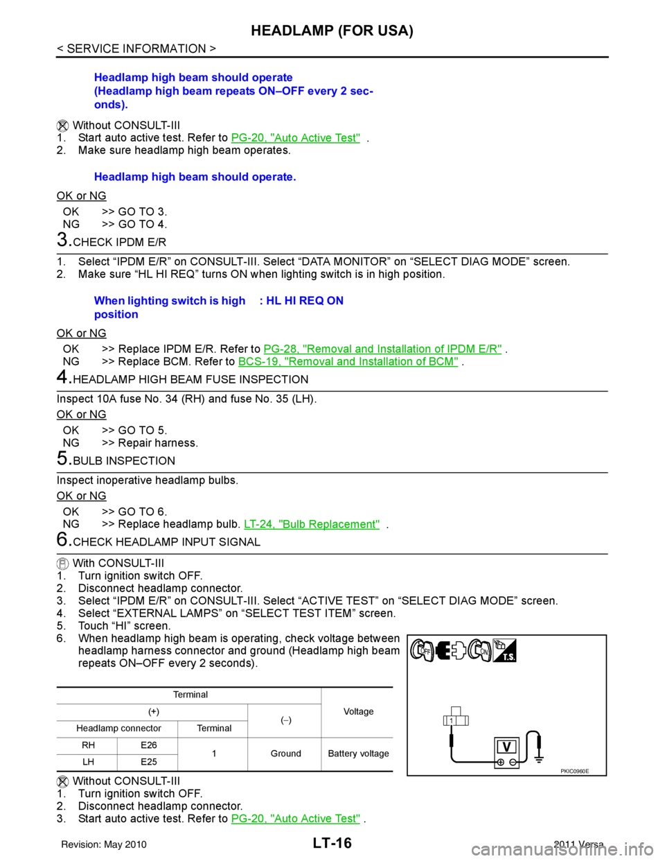
6.CHECK HEADLAMP INPUT SIGNAL
With CONSULT-III
1. Turn ignition switch OFF.
2. Disconnect headlamp connector.
3. Select “IPDM E/R” on CONSULT-III. Select “ACTIVE TEST” on “SELECT DIAG MODE” screen.
4. Select “EXTERNAL LAMPS” on “SELECT TEST ITEM” screen.
5. Touch “HI” screen.
6. When headlamp high beam is operating, check voltage between headlamp harness connector and ground (Headlamp high beam
repeats ON–OFF every 2 seconds).
Without CONSULT-III
1. Turn ignition switch OFF.
2. Disconnect headlamp connector.
3. Start auto active test. Refer to PG-20, "
Auto Active Test" .
Headlamp high beam should operate
(Headlamp high beam repeats ON–OFF every 2 sec-
onds).
Headlamp high beam should operate.
When lighting switch is high
position
: HL HI REQ ON
Te r m i n a l
Vo l ta g e
(+)
(−)
Headlamp connector Terminal
RH E26 1Ground Battery voltage
LH E25
PKIC0960E
Revision: May 2010 2011 Versa
Page 3049 of 3787
HEADLAMP (FOR USA)LT-17
< SERVICE INFORMATION >
C
DE
F
G H
I
J
L
M A
B
LT
N
O P
4. When headlamp high beam is operating, check voltage between headlamp harness connector and ground.
OK or NG
OK >> GO TO 7.
NG >> GO TO 8.
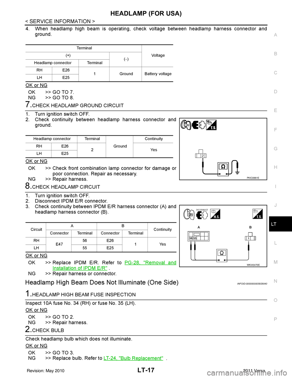
7.CHECK HEADLAMP GROUND CIRCUIT
1. Turn ignition switch OFF.
2. Check continuity between headlamp harness connector and ground.
OK or NG
OK >> Check front combination lamp connector for damage or poor connection. Repair as necessary.
NG >> Repair harness.
8.CHECK HEADLAMP CIRCUIT
1. Turn ignition switch OFF.
2. Disconnect IPDM E/R connector.
3. Check continuity between IPDM E/R harness connector (A) and headlamp harness connector (B).
OK or NG
OK >> Replace IPDM E/R. Refer to PG-28, "Removal and
Installation of IPDM E/R" .
NG >> Repair harness or connector.
Headlamp High Beam Does No t Illuminate (One Side)INFOID:0000000005929040
1.HEADLAMP HIGH BEAM FUSE INSPECTION
Inspect 10A fuse No. 34 (RH) or fuse No. 35 (LH).
OK or NG
OK >> GO TO 2.
NG >> Repair harness.
2.CHECK BULB
Check headlamp bulb which does not illuminate.
OK or NG
OK >> GO TO 3.
NG >> Replace bulb. Refer to LT-24, "
Bulb Replacement" .
Te r m i n a l
Vo l ta g e
(+)
(−)
Headlamp connector Terminal
RH E26 1Ground Battery voltage
LH E25
Headlamp connector Terminal
Ground Continuity
RH E26 2Y es
LH E25
PKIC0961E
Circuit AB
Continuity
Connector Terminal Connector Terminal
RH E47 56 E26
1 Yes
LH 55 E25
WKIA5470E
Revision: May 2010 2011 Versa
Page 3053 of 3787
HEADLAMP (FOR USA)LT-21
< SERVICE INFORMATION >
C
DE
F
G H
I
J
L
M A
B
LT
N
O P
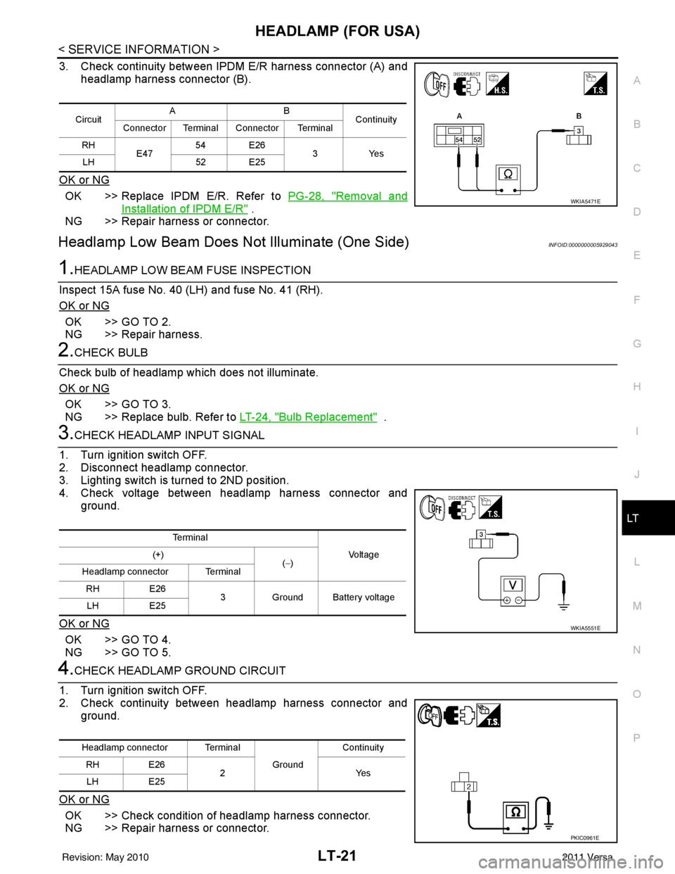
3. Check continuity between IPDM E/R harness connector (A) and headlamp harness connector (B).
OK or NG
OK >> Replace IPDM E/R. Refer to PG-28, "Removal and
Installation of IPDM E/R" .
NG >> Repair harness or connector.
Headlamp Low Beam Does Not Illuminate (One Side)INFOID:0000000005929043
1.HEADLAMP LOW BEAM FUSE INSPECTION
Inspect 15A fuse No. 40 (LH) and fuse No. 41 (RH).
OK or NG
OK >> GO TO 2.
NG >> Repair harness.
2.CHECK BULB
Check bulb of headlamp which does not illuminate.
OK or NG
OK >> GO TO 3.
NG >> Replace bulb. Refer to LT-24, "
Bulb Replacement" .
3.CHECK HEADLAMP INPUT SIGNAL
1. Turn ignition switch OFF.
2. Disconnect headlamp connector.
3. Lighting switch is turned to 2ND position.
4. Check voltage between headlamp harness connector and ground.
OK or NG
OK >> GO TO 4.
NG >> GO TO 5.
4.CHECK HEADLAMP GROUND CIRCUIT
1. Turn ignition switch OFF.
2. Check continuity between headlamp harness connector and ground.
OK or NG
OK >> Check condition of headlamp harness connector.
NG >> Repair harness or connector.
Circuit AB
Continuity
Connector Terminal Connector Terminal
RH E47 54 E26
3Yes
LH 52 E25
WKIA5471E
Te r m i n a l
Vo l ta g e
(+)
(−)
Headlamp connector Terminal
RH E26
3 Ground Battery voltage
LH E25
WKIA5551E
Headlamp connector Terminal
Ground Continuity
RH E26
2Y es
LH E25
PKIC0961E
Revision: May 2010 2011 Versa
Page 3139 of 3787
INTERIOR ROOM LAMPLT-107
< SERVICE INFORMATION >
C
DE
F
G H
I
J
L
M A
B
LT
N
O P
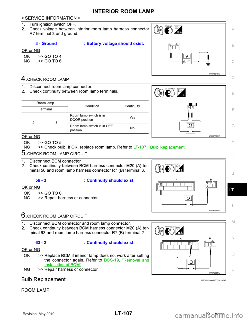
1. Turn ignition switch OFF.
2. Check voltage between interior room lamp harness connector R7 terminal 3 and ground.
OK or NG
OK >> GO TO 4.
NG >> GO TO 6.
4.CHECK ROOM LAMP
1. Disconnect room lamp connector.
2. Check continuity between room lamp terminals.
OK or NG
OK >> GO TO 5.
NG >> Check bulb. If OK, replace room lamp. Refer to LT-107, "
Bulb Replacement" .
5.CHECK ROOM LAMP CIRCUIT
1. Disconnect BCM connector.
2. Check continuity between BCM harness connector M20 (A) ter- minal 56 and room lamp harness connector R7 (B) terminal 3.
OK or NG
OK >> GO TO 6.
NG >> Repair harness or connector.
6.CHECK ROOM LAMP CIRCUIT
1. Disconnect BCM connector and room lamp connector.
2. Check continuity between BCM harness connector M20 (A) ter- minal 63 and room lamp harness connector R7 (B) terminal 2.
OK or NG
OK >> Replace BCM if interior lamp does not work after setting the connector again. Refer to BCS-19, "
Removal and
Installation of BCM" .
NG >> Repair harness or connector.
Bulb ReplacementINFOID:0000000005929148
ROOM LAMP
3 - Ground : Battery voltage should exist.
WKIA5610E
Room lamp
ConditionContinuity
Te r m i n a l
23 Room lamp switch is in
DOOR position
Ye s
Room lamp switch is in OFF
position No
WKIA5609E
56 - 3
: Continuity should exist.
WKIA5559E
63 - 2: Continuity should exist.
WKIA5560E
Revision: May 2010 2011 Versa
Page 3655 of 3787
![NISSAN TIIDA 2011 Service Repair Manual TROUBLE DIAGNOSISSRS-21
< SYMPTOM DIAGNOSIS >
C
DE
F
G
I
J
K L
M A
B
SRS
N
O P
CONSULT-III Diagnostic Code
Chart ("SELF-DIAG [CURRENT]")
Diagnostic item Explanation Repair order
Recheck SRS at each r](/manual-img/5/57396/w960_57396-3654.png "NISSAN TIIDA 2011 Service Repair Manual TROUBLE DIAGNOSISSRS-21
< SYMPTOM DIAGNOSIS >
C
DE
F
G
I
J
K L
M A
B
SRS
N
O P
CONSULT-III Diagnostic Code
Chart (\"SELF-DIAG [CURRENT]\")
Diagnostic item Explanation Repair order
Recheck SRS at each r")
TROUBLE DIAGNOSISSRS-21
< SYMPTOM DIAGNOSIS >
C
DE
F
G
I
J
K L
M A
B
SRS
N
O P
CONSULT-III Diagnostic Code
Chart ("SELF-DIAG [CURRENT]")
Diagnostic item Explanation Repair order
Recheck SRS at each replacement
NO DTC IS DETECTED Malfunction is indicat-
ed by the “AIR BAG”
warning lamp in User
mode.Low battery voltage (Less than 9V) 1. Go to
SC-5, "
How to Handle Bat-
tery".
2. Go to "DIAGNOSTIC PROCE-
DURE 3" .
“SELF-DIAG [PAST]” memory might
not be erased. Go to "DIAGNOSTIC PROCEDURE 4"
.
Intermittent malfunction has been
detected in the past. Go to "DIAGNOSTIC PROCEDURE 5"
.
No malfunction is detected in User mode. —
DRIVER AIRBAG MODULE [OPEN]
[B1049] or [B1054] Driver air bag module circuit is open (including the spiral ca-
ble).
1. Visually check the wiring harness
connection.
2. Replace the harness if it has visi- ble damage.
3. Replace driver air bag module.
4. Replace the spiral cable.
5. Replace the air bag diagnosis sensor unit.
6. Replace the related harness.
DRIVER AIRBAG MODULE
[VB-SHORT]
[B1050] or [B1055] Driver air bag module circuit is shorted to some power supply
circuit (including the spiral cable).
DRIVER AIRBAG MODULE [GND-SHORT]
[B1051] or [B1056] Driver air bag module circuit is shorted to ground (including
the spiral cable).
DRIVER AIRBAG MODULE [SHORT]
[B1052] or [B1057] Driver air bag module circuits are shorted to each other.
ASSIST A/B MODULE [OPEN]
[B1065] or [B1070] Front passenger air bag module circuit is open.
1. Visually check the wiring harness
connection.
2. Replace the harness if it has visi- ble damage.
3. Replace front passenger air bag
module.
4. Replace the air bag diagnosis sensor unit.
5. Replace the related harness.
ASSIST A/B MODULE
[VB-SHORT]
[B1066] or [B1071] Front passenger air bag module circuit is shorted to some
power supply circuit.
ASSIST A/B MODULE [GND-SHORT]
[B1067] or [B1072] Front passenger air bag module circuit is shorted to ground.
ASSIST A/B MODULE [SHORT]
[B1068] or [B1073] Front passenger air bag module circuits are shorted to each
other.
CRASH ZONE SEN [UNIT FAIL]
[B1033] or [B1034]
CRASH ZONE SEN [COMM FAIL][B1035] Crash zone sensor
1. Visually check the wiring harness
connection.
2. Replace the harness if it has visi- ble damage.
3. Replace the crash zone sensor.
4. Replace the air bag diagnosis sensor unit.
5. Replace the related harness.
SIDE MODULE LH [OPEN][B1134] Front LH side air bag module circuit is open.
1. Visually check the wiring harness
connection.
2. Replace the harness if it has visi-
ble damage.
3. Replace front LH seat back as- sembly (front LH side air bag
module).
4. Replace the air bag diagnosis sensor unit.
5. Replace the related harness.
SIDE MODULE LH
[VB-SHORT][B1135] Front LH side air bag module circuit is shorted to some power
supply circuit.
SIDE MODULE LH [GND-SHORT]
[B1136] Front LH side air bag module circuit is shorted to ground.
SIDE MODULE LH [SHORT][B 11
37] Front LH side air bag module circuits are shorted to each oth-
er.
Revision: May 2010
2011 Versa
Page 3659 of 3787

TROUBLE DIAGNOSISSRS-25
< SYMPTOM DIAGNOSIS >
C
DE
F
G
I
J
K L
M A
B
SRS
N
O P
2. Touch “TROUBLE DIAG RECORD”. NOTE:
With “TROUBLE DIAG RECORD”, di agnosis results previously erased by a reset operation can be
displayed.
3. Diagnostic code is displayed on “TROUBLE DIAG RECORD”.
4. Touch “PRINT”.
5. Compare diagnostic codes to "CONSULT-III Diagnos tic Code Chart ("SELF-DIAG [PAST]" or "TROUBLE
DIAG RECORD")".
6. Touch “BACK” key of CONSULT- III until “SELECT SYSTEM” appears.
7. Turn ignition switch OFF, then turn off and disconnect CONSULT-III, and both battery cables.
8. Repair the system as outlined by the “Repair orde r” in “Intermittent Malfunction Diagnostic Code Chart”,
that corresponds to the self-diagnostic result. For r eplacement procedure of component parts, refer to the
Removal and Installation procedure for the appropriate component.
9. Go to "DIAGNOSTIC PROCEDURE 3", for final checking.
CONSULT-III Diagnostic Code Chart ("SELF-DI AG [PAST]" or "TROUBLE DIAG RECORD")
Diagnostic item Explanation Repair order
Recheck SRS at each replacement
NO DTC IS DETECTED When malfunction is
indicated by the “AIR
BAG” warning lamp in
User mode.
• Low battery voltage (L
ess than 9V) • Go to "DIAGNOSTIC PROCEDURE
3" .
• Self-diagnostic result “SELF-DIAG [PAST]” (previously stored in the
memory) might not be erased after
repair.
• Intermittent malfunction has been detected in the past. • Go to "DIAGNOSTIC PROCEDURE
4" .
• Go to "DIAGNOSTIC PROCEDURE
5" .
• No malfunction is detected. —
DRIVER AIRBAG MODULE [OPEN]
[B1049] or [B1054] Driver air bag module circuit is open (including the spiral ca-
ble).
1. Visually check the wiring harness
connection.
2. Replace the harness if it has visi- ble damage.
3. Replace driver air bag module.
4. Replace the spiral cable.
5. Replace the air bag diagnosis sensor unit.
6. Replace the related harness.
DRIVER AIRBAG MODULE
[VB-SHORT]
[B1050] or [B1055] Driver air bag module circuit is shorted to some power supply
circuit (including the spiral cable).
DRIVER AIRBAG MODULE [GND-SHORT]
[B1051] or [B1056] Driver air bag module circuit is shorted to ground (including
the spiral cable).
DRIVER AIRBAG MODULE [SHORT]
[B1052] or [B1057] Driver air bag module circuits are shorted to each other.
ASSIST A/B MODULE [OPEN]
[B1065] or [B1070] Front passenger air bag module circuit is open.
1. Visually check the wiring harness
connection.
2. Replace the harness if it has visi-
ble damage.
3. Replace front passenger air bag module.
4. Replace the air bag diagnosis sensor unit.
5. Replace the related harness.
ASSIST A/B MODULE
[VB-SHORT]
[B1066] or [B1071] Front passenger air bag module circuit is shorted to some
power supply circuit.
ASSIST A/B MODULE [GND-SHORT]
[B1067] or [B1072] Front passenger air bag module circuit is shorted to ground.
ASSIST A/B MODULE [SHORT]
[B1068] or [B1073] Front passenger air bag module circuits are shorted to each
other.
Revision: May 2010
2011 Versa