Page 654 of 3787
BL-144
< SERVICE INFORMATION >
INTELLIGENT KEY SYSTEM
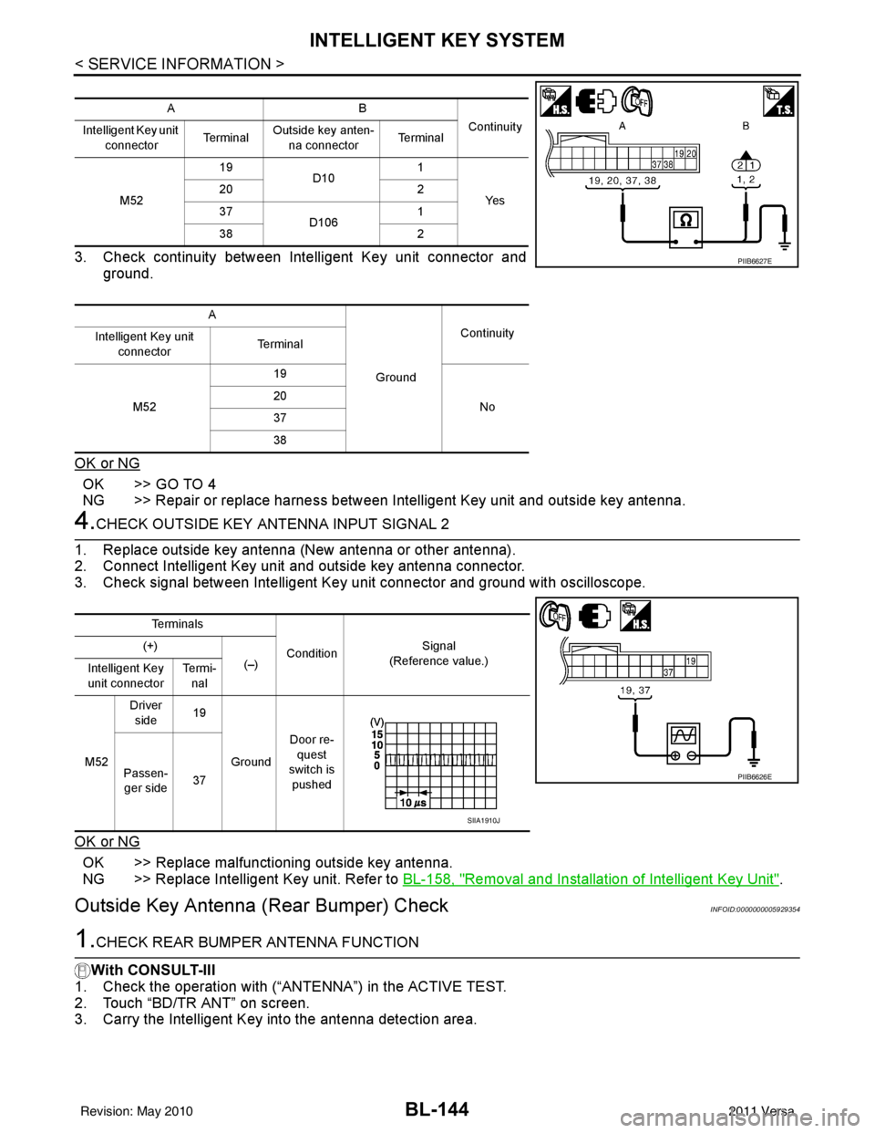
3. Check continuity between Intelligent Key unit connector andground.
OK or NG
OK >> GO TO 4
NG >> Repair or replace harness between Intelligent Key unit and outside key antenna.
4.CHECK OUTSIDE KEY ANTENNA INPUT SIGNAL 2
1. Replace outside key antenna (New antenna or other antenna).
2. Connect Intelligent Key unit and outside key antenna connector.
3. Check signal between Intelligent Key unit connector and ground with oscilloscope.
OK or NG
OK >> Replace malfunctioning outside key antenna.
NG >> Replace Intelligent Key unit. Refer to BL-158, "
Removal and Installation of Intelligent Key Unit".
Outside Key Antenna (Rear Bumper) CheckINFOID:0000000005929354
1.CHECK REAR BUMPER ANTENNA FUNCTION
With CONSULT-III
1. Check the operation with (“ANTENNA”) in the ACTIVE TEST.
2. Touch “BD/TR ANT” on screen.
3. Carry the Intelligent Key into the antenna detection area.
AB
Continuity
Intelligent Key unit
connector Te r m i n a lOutside key anten-
na connector Te r m i n a l
M52 19
D10 1
Ye s
20
2
37 D106 1
38 2
A GroundContinuity
Intelligent Key unit
connector Terminal
M52 19
No
20
37
38
PIIB6627E
Te r m i n a l s
Condition Signal
(Reference value.)
(+)
(–)
Intelligent Key
unit connector Te r m i -
nal
M52 Driver
side 19
Ground Door re-
quest
switch is
pushed
Passen-
ger side 37
PIIB6626E
SIIA1910J
Revision: May 2010
2011 Versa
Page 655 of 3787
INTELLIGENT KEY SYSTEMBL-145
< SERVICE INFORMATION >
C
DE
F
G H
J
K L
M A
B
BL
N
O P
Do the hazard lamps flash?
Yes >> Rear bumper antenna is OK.
No >> GO TO 2
2.CHECK REAR BUMPER ANTENNA INPUT SIGNAL 1
1. Turn ignition switch OFF.
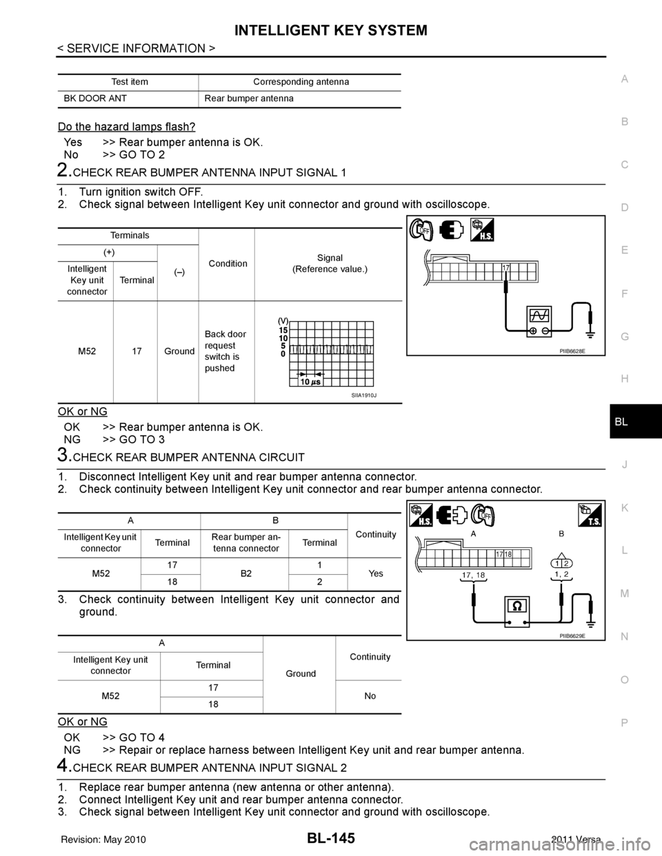
2. Check signal between Intelligent Key unit connector and ground with oscilloscope.
OK or NG
OK >> Rear bumper antenna is OK.
NG >> GO TO 3
3.CHECK REAR BUMPER ANTENNA CIRCUIT
1. Disconnect Intelligent Key unit and rear bumper antenna connector.
2. Check continuity between Intelligent Key unit connector and rear bumper antenna connector.
3. Check continuity between Intelligent Key unit connector and ground.
OK or NG
OK >> GO TO 4
NG >> Repair or replace harness between Intelligent Key unit and rear bumper antenna.
4.CHECK REAR BUMPER ANTENNA INPUT SIGNAL 2
1. Replace rear bumper antenna (new antenna or other antenna).
2. Connect Intelligent Key unit and rear bumper antenna connector.
3. Check signal between Intelligent Key unit connector and ground with oscilloscope.
Test item Corresponding antenna
BK DOOR ANT Rear bumper antenna
Te r m i n a l s
Condition Signal
(Reference value.)
(+)
(–)
Intelligent
Key unit
connector Te r m i n a l
M52 17 Ground Back door
request
switch is
pushed
PIIB6628E
SIIA1910J
AB
Continuity
Intelligent Key unit
connector Te r m i n a l
Rear bumper an-
tenna connector Te r m i n a l
M52 17
B2 1
Ye s
18 2
A GroundContinuity
Intelligent Key unit
connector Te r m i n a l
M52 17
No
18
PIIB6629E
Revision: May 2010 2011 Versa
Page 656 of 3787
BL-146
< SERVICE INFORMATION >
INTELLIGENT KEY SYSTEM
OK or NG
OK >> Replace rear bumper antenna.
NG >> Replace Intelligent Key unit. Refer to BL-158, "
Removal and Installation of Intelligent Key Unit".
Inside Key Antenna CheckINFOID:0000000005929355
1.CHECK INSIDE KEY ANTENNA INPUT SIGNAL 1
1. Turn ignition switch OFF.
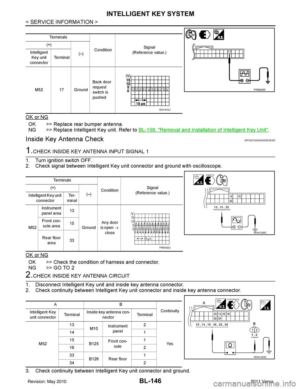
2. Check signal between Intelligent Key unit connector and ground with oscilloscope.
OK or NG
OK >> Check the condition of harness and connector.
NG >> GO TO 2
2.CHECK INSIDE KEY ANTENNA CIRCUIT
1. Disconnect Intelligent Key unit and inside key antenna connector.
2. Check continuity between Intelligent Key unit connector and inside key antenna connector.
3. Check continuity between Intelligent Key unit connector and ground.
Te r m i n a l s
Condition Signal
(Reference value.)
(+)
(–)
Intelligent
Key unit
connector Te r m i n a l
M52 17 Ground Back door
request
switch is
pushed
PIIB6628E
SIIA1910J
Te r m i n a l s
ConditionSignal
(Reference value.)
(+)
(–)
Intelligent Key unit
connector Te r -
minal
M52 Instrument
panel area 13
Ground Any door
is open →
close
Front con-
sole area 15
Rear floor area 33
WIIA1200E
PIIB5502J
AB
Continuity
Intelligent Key
unit connector Te r m i n a lInside key antenna con-
nector Te r m i n a l
M52 13
M10Instrument
panel 2
Ye s
14
1
15 B125Front con-
sole 1
16 2
33 B126 Rear floor 1
34 2
WIIA1254E
Revision: May 2010 2011 Versa
Page 657 of 3787
INTELLIGENT KEY SYSTEMBL-147
< SERVICE INFORMATION >
C
DE
F
G H
J
K L
M A
B
BL
N
O P
OK or NG
OK >> GO TO 3
NG >> Repair or replace harness between Intelligent Key unit and inside key antenna.
3.CHECK INSIDE KEY ANTENNA INPUT SIGNAL 2
1. Replace inside key antenna. (New antenna or other antenna)
2. Connect Intelligent Key unit and inside key antenna connector.
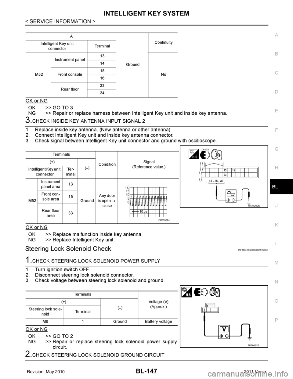
3. Check signal between Intelligent Key unit connector and ground with oscilloscope.
OK or NG
OK >> Replace malfunction inside key antenna.
NG >> Replace Intelligent Key unit.
Steering Lock Solenoid CheckINFOID:0000000005929356
1.CHECK STEERING LOCK SOLENOID POWER SUPPLY
1. Turn ignition switch OFF.
2. Disconnect steering lock solenoid connector.
3. Check voltage between steering lock solenoid and ground.
OK or NG
OK >> GO TO 2
NG >> Repair or replace steering lock solenoid power supply circuit.
2.CHECK STEERING LOCK SOLENOID GROUND CIRCUIT
A
GroundContinuity
Intelligent Key unit
connector Te r m i n a l
M52 Instrument panel
13
No
14
Front console 15
16
Rear floor 33
34
Te r m i n a l s
ConditionSignal
(Reference value.)
(+)
(–)
Intelligent Key unit
connector Te r -
minal
M52 Instrument
panel area 13
Ground Any door
is open →
close
Front con-
sole area 15
Rear floor area 33
WIIA1200E
PIIB5502J
Te r m i n a l s
Voltage (V)(Approx.)
(+)
(–)
Steering lock sole-
noid Te r m i n a l
M6 1Ground Battery voltage
PIIB6632E
Revision: May 2010 2011 Versa
Page 670 of 3787
BL-160
< SERVICE INFORMATION >
DOOR
DOOR
Fitting AdjustmentINFOID:0000000005929373
FRONT DOOR
Longitudinal Clearance at Front End
Access from inside the fender to loosen the hinge bolts. Raise the front door at rear end to adjust.
Surface Height Adjustment
Loosen the front door bolts, and adjust the surface height difference of fender and front door according to the
fitting standard dimension.
Striker Adjustment
1. Front fender2. Front door outer3. Rear door outer
4. Rear fender 5. Front door weatherstrip 6. Front door sash
7. Rear door weatherstrip 8. Rear door sash
PIIB6516E
Revision: May 2010 2011 Versa
Page 671 of 3787
DOOR
BL-161
< SERVICE INFORMATION >
C
D E
F
G H
J
K L
M A
B
BL
N
O P
REAR DOOR
Longitudinal Clearance and Surface Height Adjustment at Front End
1. Remove the center pillar upper and lower garnishes. Refer to EI-41.
2. Access from inside the vehicle to loosen the hinge nuts. Open the rear door, and raise the rear door at
rear end to adjust.
Surface Height Adjustment
Loosen the front door striker bolts and rear door hinge nu ts, and adjust the surface height difference of front
and rear doors according to the fitting standard dimension.
Striker Adjustment
BACK DOOR
Longitudinal Clearance and Surface Height Adjustment
16.7 N·m (1.7 kg-m, 12 ft-lb)
PIIB2804J
16.7 N·m (1.7 kg-m, 12 ft-lb)
PIIB2804J
Revision: May 2010 2011 Versa
Page 672 of 3787
BL-162
< SERVICE INFORMATION >
DOOR
1. Open and support the back door.
2. Slightly loosen the hinge nuts.
3. Reposition the door as necessary and tighten the nuts.
4. Confirm the adjustment. Repeat as necessary to obtain the desired fit.
Striker Adjustment
1. Back door assembly2. Back door hinge 3. Tail lamp assembly
4. Back window glass 5. Roof 6. Rear pillar
A. 6.0 ± 1.0 mm (0.24 ± 0.04 in) B. -0.5 ± 1.0 mm (-0.02 ± 0.04 in) C. 5.0 ± 1.2 mm (0.20 ± 0.05 in)
D. 0.0 ± 1.5 mm (0.0 ± 0.06 in) E. 5.0 ± 2.3 mm ( 0.20 ± 0.9 in) F. 2.7 +1.6 -2.1 mm (0.11 + 0.06 - 0.08 in)
G. 5.0 ± 1.2 mm ( 0.20 ± 0.05 in) H. 0.0 ± 1.5 mm (0.0 ± 0.06 in)
LIIA2668E
Revision: May 2010 2011 Versa
Page 673 of 3787
DOOR
BL-163
< SERVICE INFORMATION >
C
D E
F
G H
J
K L
M A
B
BL
N
O P
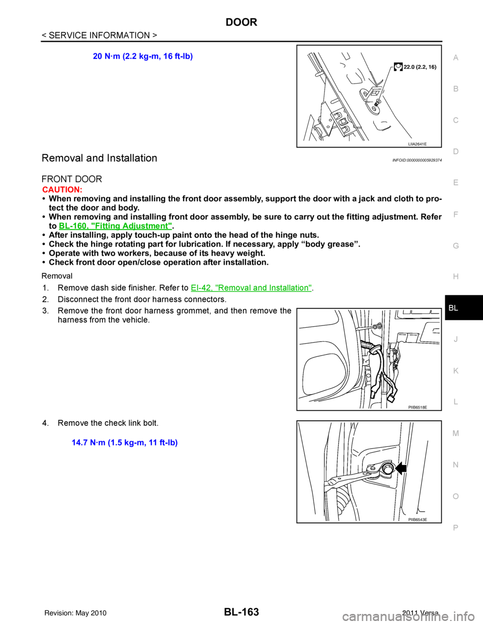
Removal and InstallationINFOID:0000000005929374
FRONT DOOR
CAUTION:
• When removing and installing the front door assembly, support the door with a jack and cloth to pro-
tect the door and body.
• When removing and installing front door assembly, be sure to carry out the fitting adjustment. Refer
to BL-160, "
Fitting Adjustment".
• After installing, apply touch-up pain t onto the head of the hinge nuts.
• Check the hinge rotating pa rt for lubrication. If necessary, apply “body grease”.
• Operate with two workers, because of its heavy weight.
• Check front door open/close op eration after installation.
Removal
1. Remove dash side finisher. Refer to EI-42, "Removal and Installation".
2. Disconnect the front door harness connectors.
3. Remove the front door harness grommet, and then remove the harness from the vehicle.
4. Remove the check link bolt. 20 N·m (2.2 kg-m, 16 ft-lb)
LIIA2641E
PIIB6518E
14.7 N·m (1.5 kg-m, 11 ft-lb)
PIIB6543E
Revision: May 2010
2011 Versa