Page 3406 of 3787

MTC-90
< SERVICE INFORMATION >
REFRIGERANT LINES
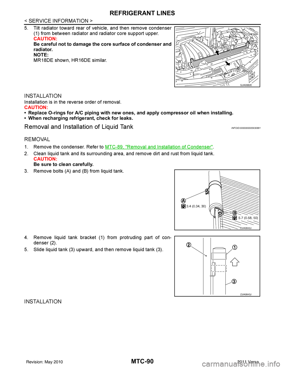
5. Tilt radiator toward rear of vehicle, and then remove condenser(1) from between radiator and radiator core support upper.
CAUTION:
Be careful not to damage the core surface of condenser and
radiator.
NOTE:
MR18DE shown, HR16DE similar.
INSTALLATION
Installation is in the reverse order of removal.
CAUTION:
• Replace O-rings for A/C piping with new ones, and apply compressor oil when installing.
• When recharging refrigerant, check for leaks.
Removal and Installation of Liquid TankINFOID:0000000005930881
REMOVAL
1. Remove the condenser. Refer to MTC-89, "Removal and Installation of Condenser".
2. Clean liquid tank and its surrounding area, and remove dirt and rust from liquid tank. CAUTION:
Be sure to clean carefully.
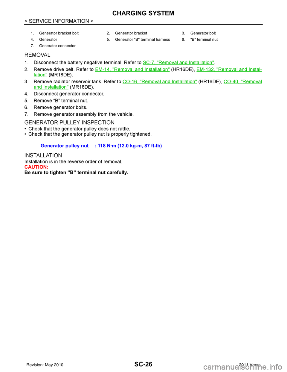
3. Remove bolts (A) and (B) from liquid tank.
4. Remove liquid tank bracket (1) from protruding part of con- denser (2).
5. Slide liquid tank (3) upward, and then remove liquid tank (3).
INSTALLATION
SJIA0682E
ZJIA0842J
ZJIA0843J
Revision: May 2010 2011 Versa
Page 3531 of 3787

RF-8
< SYMPTOM DIAGNOSIS >
SQUEAK AND RATTLE TROUBLE DIAGNOSES
2. Trunk lid striker out of adjustment
3. The trunk lid torsion bars knocking together
4. A loose license plate or bracket
Most of these incidents can be repaired by adjusting, securing or insulating the item(s) or component(s) caus-
ing the noise.
SUNROOF/HEADLINING
Noises in the sunroof/headlining area c an often be traced to one of the following:
1. Sunroof lid, rail, linkage or seals making a rattle or light knocking noise
2. Sun visor shaft shaking in the holder
3. Front or rear windshield touching headliner and squeaking
Again, pressing on the components to stop the noise while duplicating the conditions can isolate most of these
incidents. Repairs usually consist of insulating with felt cloth tape.
OVERHEAD CONSOLE (FRONT AND REAR)
Overhead console noises are often caused by the c onsole panel clips not being engaged correctly. Most of
these incidents are repaired by pushing up on the c onsole at the clip locations until the clips engage.
In addition look for:
1. Loose harness or harness connectors.
2. Front console map/reading lamp lens loose.
3. Loose screws at console attachment points.
SEATS
When isolating seat noise it's important to note the pos ition the seat is in and the load placed on the seat when
the noise is present. These conditions should be duplicated when verifying and isolating the cause of the
noise.
Cause of seat noise include:
1. Headrest rods and holder
2. A squeak between the seat pad cushion and frame
3. The rear seatback lock and bracket
These noises can be isolated by moving or pressing on the suspected components while duplicating the con-
ditions under which the noise occurs. Most of thes e incidents can be repaired by repositioning the component
or applying urethane tape to the contact area.
UNDERHOOD
Some interior noise may be caused by components under the hood or on the engine wall. The noise is then
transmitted into the passenger compartment.
Causes of transmitted underhood noise include:
1. Any component installed on the engine wall
2. Components that pass through the engine wall
3. Engine wall mounts and connectors
4. Loose radiator pins
5. Hood bumpers out of adjustment
6. Hood striker out of adjustment
These noises can be difficult to isolate since they cannot be reached from the interior of the vehicle. The best
method is to secure, move or insulate one component at a time and test drive the \
vehicle. Also, engine RPM
or load can be changed to isolate the noise. Repairs can usually be made by moving, adjusting, securing, or
insulating the component causing the noise.
Revision: May 2010 2011 Versa
Page 3604 of 3787

SC-26
< SERVICE INFORMATION >
CHARGING SYSTEM
REMOVAL
1. Disconnect the battery negative terminal. Refer to SC-7, "Removal and Installation".
2. Remove drive belt. Refer to EM-14, "
Removal and Installation" (HR16DE), EM-132, "Removal and Instal-
lation" (MR18DE).
3. Remove radiator reservoir tank. Refer to CO-16, "
Removal and Installation" (HR16DE), CO-40, "Removal
and Installation" (MR18DE).
4. Disconnect generator connector.
5. Remove “B” terminal nut.
6. Remove generator bolts.
7. Remove generator assembly from the vehicle.
GENERATOR PULLEY INSPECTION
• Check that the generator pulley does not rattle.
• Check that the generator pulley nut is properly tightened.
INSTALLATION
Installation is in the reverse order of removal.
CAUTION:
Be sure to tighten “B” terminal nut carefully.
1. Generator bracket bolt 2. Generator bracket3. Generator bolt
4. Generator 5. Generator "B" terminal harness 6. "B" terminal nut
7. Generator connector
Generator pulley nut : 118 N·m (12.0 kg-m, 87 ft-lb)
Revision: May 2010 2011 Versa
Page 3613 of 3787

SE-8
< SERVICE INFORMATION >
SQUEAK AND RATTLE TROUBLE DIAGNOSES
Most of these incidents can be repaired by adjusting, securing or insulating the item(s) or component(s) caus-
ing the noise.
SUNROOF/HEADLINING
Noises in the sunroof/headlining area c an often be traced to one of the following:
1. Sunroof lid, rail, linkage or seals making a rattle or light knocking noise
2. Sun visor shaft shaking in the holder
3. Front or rear windshield touching headliner and squeaking
Again, pressing on the components to stop the noise while duplicating the conditions can isolate most of these
incidents. Repairs usually consist of insulating with felt cloth tape.
OVERHEAD CONSOLE (FRONT AND REAR)
Overhead console noises are often caused by the c onsole panel clips not being engaged correctly. Most of
these incidents are repaired by pushing up on the c onsole at the clip locations until the clips engage.
In addition look for:
1. Loose harness or harness connectors.
2. Front console map/reading lamp lense loose.
3. Loose screws at console attachment points.
SEATS
When isolating seat noise it's important to note the pos ition the seat is in and the load placed on the seat when
the noise is present. These conditions should be duplicated when verifying and isolating the cause of the
noise.
Cause of seat noise include:
1. Headrest rods and holder
2. A squeak between the seat pad cushion and frame
3. The rear seatback lock and bracket
These noises can be isolated by moving or pressing on the suspected components while duplicating the con-
ditions under which the noise occurs. Most of thes e incidents can be repaired by repositioning the component
or applying urethane tape to the contact area.
UNDERHOOD
Some interior noise may be caused by components under the hood or on the engine wall. The noise is then
transmitted into the passenger compartment.
Causes of transmitted underhood noise include:
1. Any component mounted to the engine wall
2. Components that pass through the engine wall
3. Engine wall mounts and connectors
4. Loose radiator mounting pins
5. Hood bumpers out of adjustment
6. Hood striker out of adjustment
These noises can be difficult to isolate since they cannot be reached from the interior of the vehicle. The best
method is to secure, move or insulate one component at a time and test drive the \
vehicle. Also, engine RPM
or load can be changed to isolate the noise. Repairs can usually be made by moving, adjusting, securing, or
insulating the component causing the noise.
Revision: May 2010 2011 Versa
Page 3676 of 3787

SRS-42
< ON-VEHICLE REPAIR >
CRASH ZONE SENSOR
CRASH ZONE SENSOR
Removal and InstallationINFOID:0000000005931216
REMOVAL
CAUTION:
• Before servicing the SRS, turn ignition switch OFF, disconnect both battery terminals and wait at
least three minutes.
• Do not disassemble the crash zone sensor.
• Do not use old nuts after removal; replace with new nuts.
• Replace the crash zone sensor if it has been dropped or sus- tained an impact.
• Check crash zone sensor to make sure it is free of deformi-
ties, dents, cracks or rust. If it shows any visible signs of dam-
age, replace it with a new one.
1. Disconnect both the negative and positive battery terminals, then wait at least three minutes.
2. Remove air intake duct. Refer to EM-25, "
Exploded View" (HR16DE), EM-135, "Component" (MR18DE).
3. Remove upper radiator cover and front grille, refer to EI-23
.
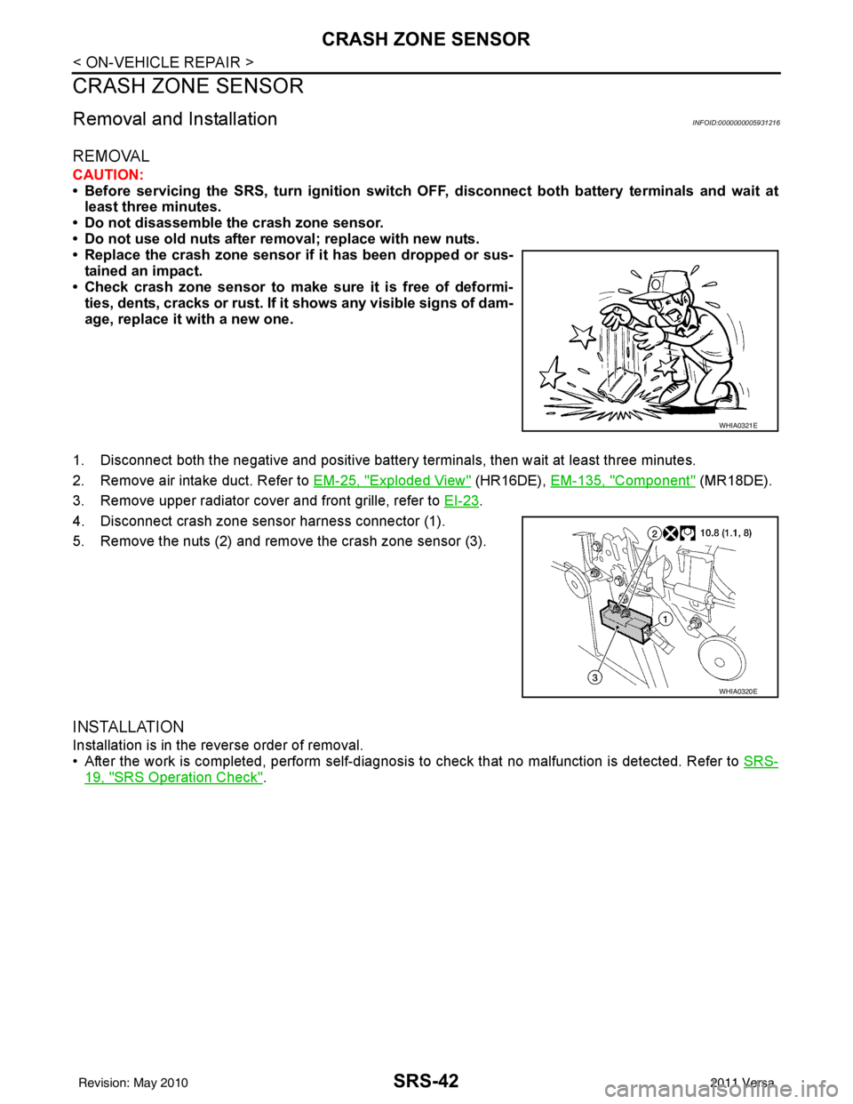
4. Disconnect crash zone sensor harness connector (1).
5. Remove the nuts (2) and remove the crash zone sensor (3).
INSTALLATION
Installation is in the reverse order of removal.
• After the work is completed, perform self-diagnosis to check that no malfunction is detected. Refer to SRS-
19, "SRS Operation Check".
WHIA0321E
WHIA0320E
Revision: May 2010 2011 Versa