2011 NISSAN TIIDA radiator
[x] Cancel search: radiatorPage 3198 of 3787
ENGINE MAINTENANCE (MR18DE)MA-27
< SERVICE INFORMATION >
C
DE
F
G H
I
J
K
M A
B
MA
N
O P
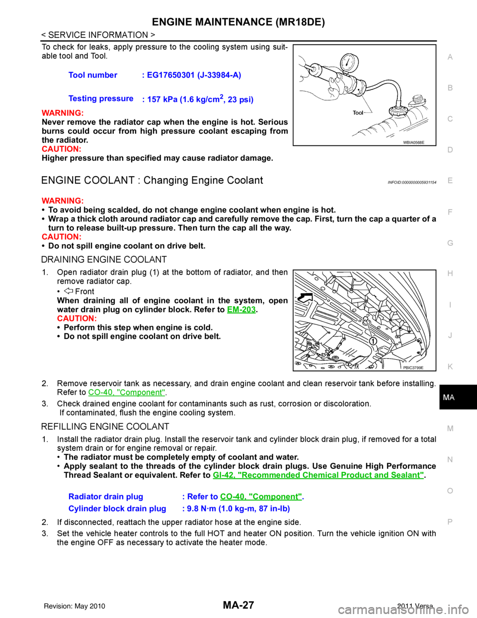
To check for leaks, apply pressure to the cooling system using suit-
able tool and Tool.
WARNING:
Never remove the radiator cap wh en the engine is hot. Serious
burns could occur from high pressure coolant escaping from
the radiator.
CAUTION:
Higher pressure than specified may cause radiator damage.
ENGINE COOLANT : Chang ing Engine CoolantINFOID:0000000005931154
WARNING:
• To avoid being scalded, do not change engine coolant when engine is hot.
• Wrap a thick cloth around radiator cap and carefully remove the cap. First, turn the cap a quarter of a
turn to release built-up pressure. Then turn the cap all the way.
CAUTION:
• Do not spill engine coolant on drive belt.
DRAINING ENGINE COOLANT
1. Open radiator drain plug (1) at the bottom of radiator, and then remove radiator cap.
• Front
When draining all of engine coolant in the system, open
water drain plug on cylinder block. Refer to EM-203
.
CAUTION:
• Perform this step when engine is cold.
• Do not spill engine coolant on drive belt.
2. Remove reservoir tank as necessary, and drain engi ne coolant and clean reservoir tank before installing.
Refer to CO-40, "
Component".
3. Check drained engine coolant for contaminants such as rust, corrosion or discoloration. If contaminated, flush the engine cooling system.
REFILLING ENGINE COOLANT
1. Install the radiator drain plug. Install the reservoir tank and cylinder block drain plug, if removed for a total
system drain or for engine removal or repair.
• The radiator must be completely empty of coolant and water.
• Apply sealant to the threads of the cylinder blo ck drain plugs. Use Genuine High Performance
Thread Sealant or equivalent. Refer to GI-42, "
Recommended Chemical Product and Sealant".
2. If disconnected, reattach the upper radiator hose at the engine side.
3. Set the vehicle heater controls to the full HOT and heat er ON position. Turn the vehicle ignition ON with
the engine OFF as necessary to activate the heater mode. Tool number : EG17650301 (J-33984-A)
Testing pressure
: 157 kPa (1.6 kg/cm
2, 23 psi)
WBIA0568E
PBIC3799E
Radiator drain plug : Refer to CO-40, "Component".
Cylinder block drain plug : 9.8 N·m (1.0 kg-m, 87 in-lb)
Revision: May 2010 2011 Versa
Page 3199 of 3787
MA-28
< SERVICE INFORMATION >
ENGINE MAINTENANCE (MR18DE)
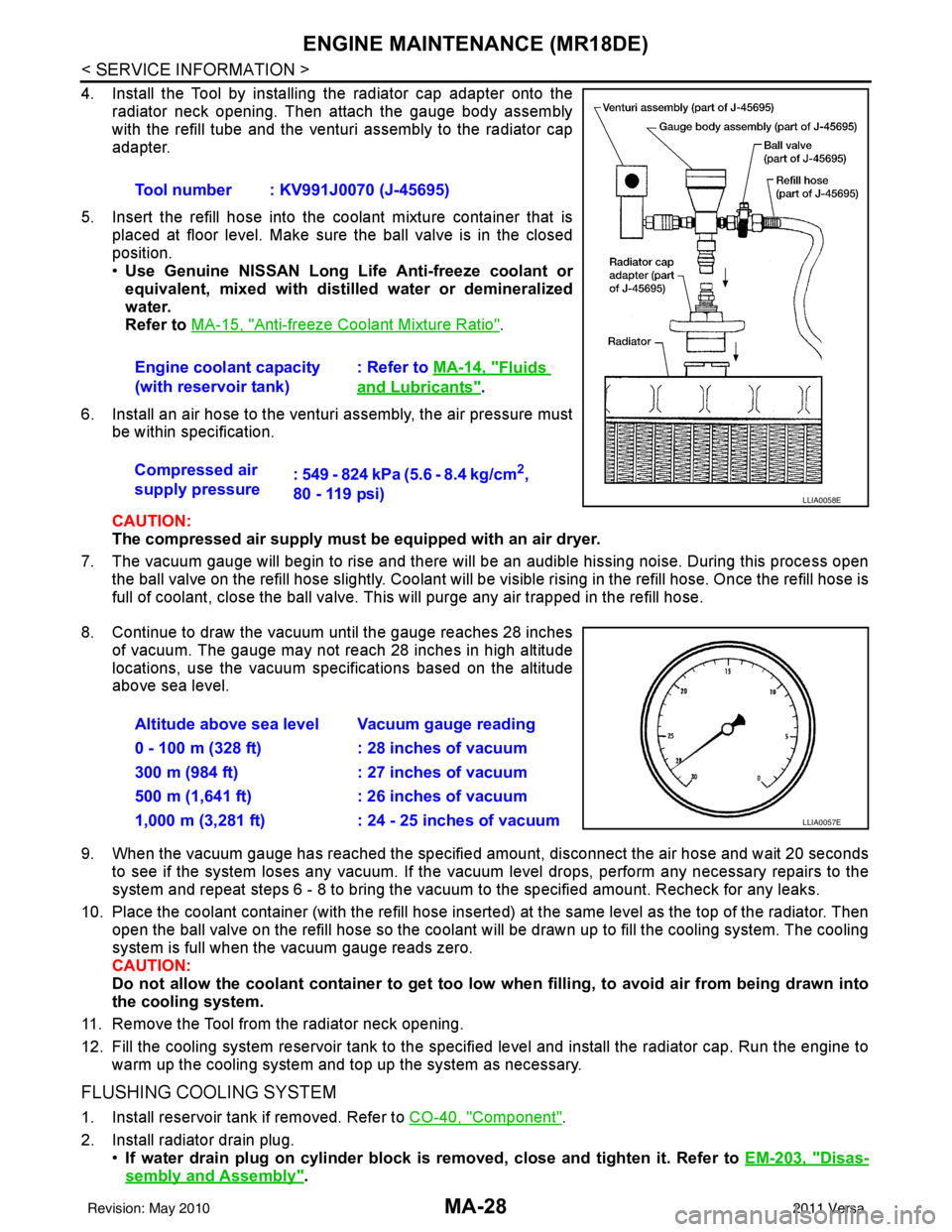
4. Install the Tool by installing the radiator cap adapter onto theradiator neck opening. Then attach the gauge body assembly
with the refill tube and the venturi assembly to the radiator cap
adapter.
5. Insert the refill hose into the coolant mixture container that is placed at floor level. Make sure the ball valve is in the closed
position.
•Use Genuine NISSAN Long Life Anti-freeze coolant or
equivalent, mixed with distil led water or demineralized
water.
Refer to MA-15, "
Anti-freeze Coolant Mixture Ratio".
6. Install an air hose to the venturi assembly, the air pressure must be within specification.
CAUTION:
The compressed air supply must be equipped with an air dryer.
7. The vacuum gauge will begin to rise and there will be an audible hissing noise. During this process open the ball valve on the refill hose slightly. Coolant will be vi sible rising in the refill hose. Once the refill hose is
full of coolant, close the ball valve. This will purge any air trapped in the refill hose.
8. Continue to draw the vacuum until the gauge reaches 28 inches of vacuum. The gauge may not reach 28 inches in high altitude
locations, use the vacuum specifications based on the altitude
above sea level.
9. When the vacuum gauge has reached the specifi ed amount, disconnect the air hose and wait 20 seconds
to see if the system loses any vacuum. If the vacuum level drops, perform any necessary repairs to the
system and repeat steps 6 - 8 to bring the vacuum to the specified amount. Recheck for any leaks.
10. Place the coolant container (with the refill hose insert ed) at the same level as the top of the radiator. Then
open the ball valve on the refill hose so the coolant will be drawn up to fill the cooling system. The cooling
system is full when the vacuum gauge reads zero.
CAUTION:
Do not allow the coolant container to get too low when filling, to avoid air from being drawn into
the cooling system.
11. Remove the Tool from the radiator neck opening.
12. Fill the cooling system reservoir tank to the specified level and install the radiator cap. Run the engine to warm up the cooling system and t op up the system as necessary.
FLUSHING COOLING SYSTEM
1. Install reservoir tank if removed. Refer to CO-40, "Component".
2. Install radiator drain plug. •If water drain plug on cylinder block is removed, close and tighten it. Refer to EM-203, "
Disas-
sembly and Assembly".
Tool number : KV991J0070 (J-45695)
Engine coolant capacity
(with reservoir tank)
: Refer to
MA-14, "
Fluids
and Lubricants".
Compressed air
supply pressure : 549 - 824 kPa (5.6 - 8.4 kg/cm
2,
80 - 119 psi)
LLIA0058E
Altitude above sea level Vacuum gauge reading
0 - 100 m (328 ft) : 28 inches of vacuum
300 m (984 ft) : 27 inches of vacuum
500 m (1,641 ft) : 26 inches of vacuum
1,000 m (3,281 ft) : 24 - 25 inches of vacuum
LLIA0057E
Revision: May 2010 2011 Versa
Page 3200 of 3787
ENGINE MAINTENANCE (MR18DE)MA-29
< SERVICE INFORMATION >
C
DE
F
G H
I
J
K
M A
B
MA
N
O P
CAUTION:
Be sure to clean radiator drain plug and install with new O-ring. Refer to CO-40, "
Component".
3. Fill radiator and reservoir tank with water and reinstall radiator cap.
4. Run engine and warm it up to normal operating temperature.
5. Rev engine two or three times under no-load.
6. Stop engine and wait until it cools down.
7. Drain water from the cooling system.
8. Repeat steps 1 through 7 until clear water begins to drain from radiator.
FUEL LINES
FUEL LINES : Checking Fuel LineINFOID:0000000005931155
Inspect fuel lines, fuel filler cap and fuel tank for improper attach-
ment, leaks, cracks, damage, loos e connections, chafing or deterio-
ration.
If necessary, repair or replace damaged parts.
AIR CLEANER FILTER
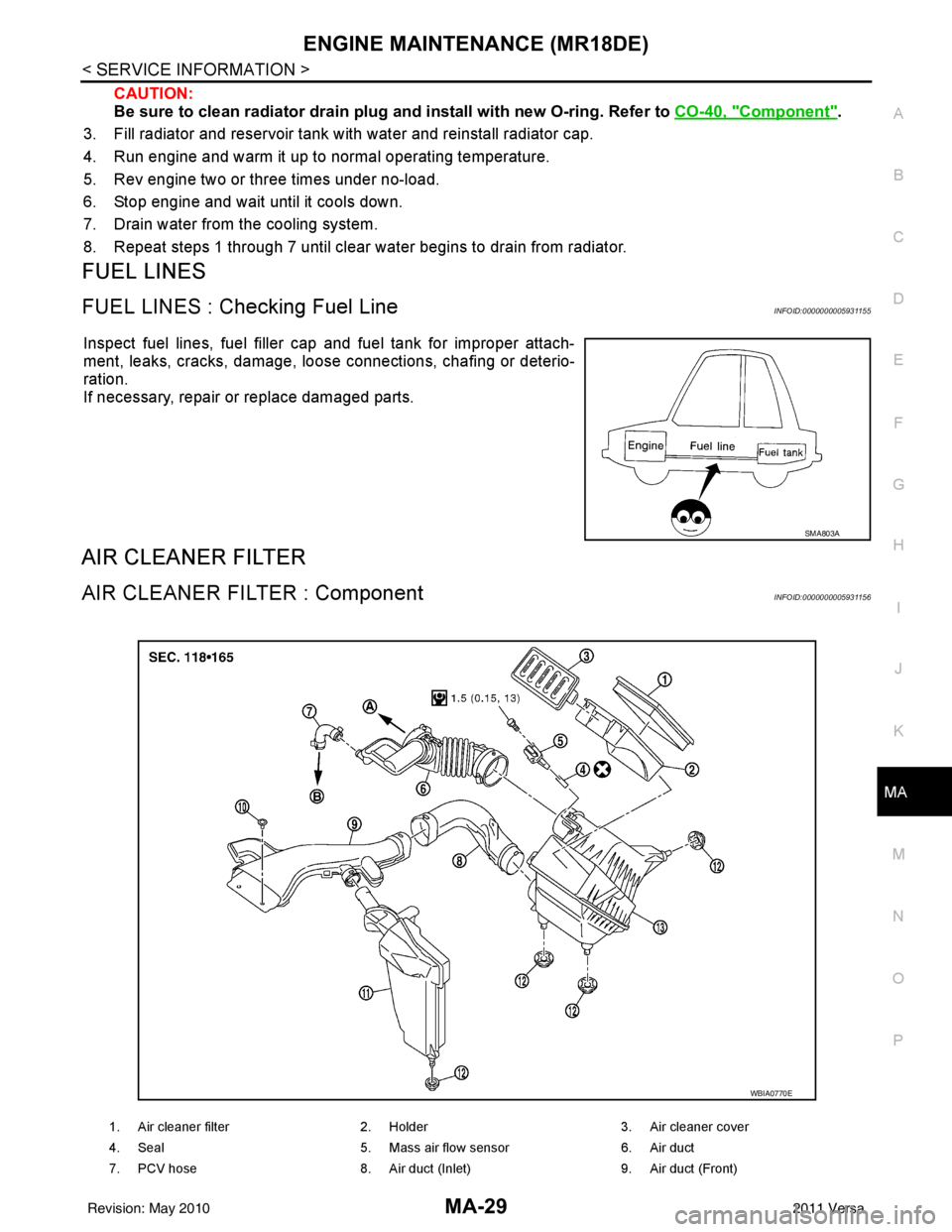
AIR CLEANER FILTER : ComponentINFOID:0000000005931156
SMA803A
1. Air cleaner filter 2. Holder 3. Air cleaner cover
4. Seal 5. Mass air flow sensor 6. Air duct
7. PCV hose 8. Air duct (Inlet) 9. Air duct (Front)
WBIA0770E
Revision: May 2010 2011 Versa
Page 3210 of 3787
![NISSAN TIIDA 2011 Service Repair Manual CHASSIS AND BODY MAINTENANCEMA-39
< SERVICE INFORMATION >
C
DE
F
G H
I
J
K
M A
B
MA
N
O P
• : Vehicle front
• Radiator (2)
• CVT fluid cooler hose [inlet side (3)]
• Transaxle assembly (4)
2. NISSAN TIIDA 2011 Service Repair Manual CHASSIS AND BODY MAINTENANCEMA-39
< SERVICE INFORMATION >
C
DE
F
G H
I
J
K
M A
B
MA
N
O P
• : Vehicle front
• Radiator (2)
• CVT fluid cooler hose [inlet side (3)]
• Transaxle assembly (4)
2.](/manual-img/5/57396/w960_57396-3209.png)
CHASSIS AND BODY MAINTENANCEMA-39
< SERVICE INFORMATION >
C
DE
F
G H
I
J
K
M A
B
MA
N
O P
• : Vehicle front
• Radiator (2)
• CVT fluid cooler hose [inlet side (3)]
• Transaxle assembly (4)
2. Drain CVT fluid from CVT fluid cooler hose [outlet side (1)] and refill with new specified NISSAN CVT fluid in the CVT fluid
charging pipe with the engine running at idle speed.
CAUTION:
Only use the specifi ed NISSAN CVT fluid.
3. Refill until new CVT fluid comes out from CVT fluid cooler hose [outlet side (1)]. NOTE:
About 30 to 50% extra fluid will be required for this procedure.
4. Check fluid level and condition. Refer to MA-37, "
CVT FLUID : Checking CVT Fluid".
CAUTION:
Delete CVT fluid deterioration date with CONSULT-III after changing CVT fluid. Refer to CVT-48,
"CONSULT-III Function (TRANSMISSION)".
CLUTCH FLUID
CLUTCH FLUID : Air Bleeding ProcedureINFOID:0000000005931169
CAUTION:
Do not spill clutch fluid onto painted surfaces. If it spills, wipe up immediately and wash the affected
area with water.
NOTE:
• Do not use a vacuum assist or any other type of power bleeder on this system. Use of a vacuum assist or power bleeder will not purge all the air from the system.
• Carefully monitor fluid level in reservoir tank during bleeding operation.
1. Fill master cylinder reservoir tank with new clutch fluid.
2. Connect a transparent vinyl tube and container to the bleeding connector (1) on the CSC.
3. Depress and release the clutch pedal slowly and fully 15 times at an interval of two to three seconds and release the clutch
pedal.
4. Push in the lock pin (1) of the bleeding connector (2), and maintain the position. • RS5F91R transaxle models
CAUTION:
Hold the lock pin in to preven t the bleeding connector from
separating when fluid pressure is applied.
Fluid capacity and grade: Refer to
MA-14, "
Fluids
and Lubricants".SCIA6088E
PCIB1494E
PCIB1495E
Revision: May 2010 2011 Versa
Page 3214 of 3787
CHASSIS AND BODY MAINTENANCEMA-43
< SERVICE INFORMATION >
C
DE
F
G H
I
J
K
M A
B
MA
N
O P
Do not overfill.
4. Drive vehicle for approximately 5 minutes.
5. Re-check A/T fluid level at A/T fluid temperatures of 50° to 80 °C (122° to 176°F) using “HOT” range on A/
T fluid level gauge.
CAUTION:
• When wiping the A/T fluid level gauge, always use lint-free cloth.
• Firmly fix the A/T fluid level ga uge to the A/T fluid charging pipe using the stopper attached.
6. Check A/T fluid condition and make any necessary repairs. Refer to AT-51, "
Inspections Before Trouble
Diagnosis". If the A/T fluid contains frictional material (clutches, bands, etc.), or if the A/T is repaired, over-
hauled, or replaced, inspect and clean the A/T fluid cooler mounted in the radiator. Refer to AT-18, "
A/T
Fluid Cooler Cleaning".
7. Install the removed A/T fluid level gauge into the A/T fluid charging pipe. CAUTION:
Firmly fix the A/T fluid level gaug e to the A/T fluid charging pipe using the stopper attached.
A/T FLUID : Changing A/T FluidINFOID:0000000005931176
1. Warm up A/T fluid.
2. Stop engine.
3. Drain A/T fluid by removing the drain plug. Re install the drain plug to the specified torque.
CAUTION:
Do not reuse drain plug gasket.
4. Refill the transaxle with new specified A/T fluid through the A/T fluid charging pipe. Always refill the tran- saxle with the same volume of A/T fluid that was drained out.
5. Run engine at idle speed for 5 minutes.
6. Check A/T fluid level and condition. Refer to MA-42, "
A/T FLUID : Checking A/T Fluid".
WHEELS
WHEELS : AdjustmentINFOID:0000000006413331
BALANCING WHEELS (ADHESIVE WEIGHT TYPE)
Preparation Before Adjustment
Remove inner and outer balance weights from the r oad wheel using releasing agent, remove double-faced
adhesive tape from the road wheel.
CAUTION:
• Be careful not scratch the road wheel during removal.
• After removing double-faced adhesive tape, wipe clean traces of releasing agent from the road
wheel.
Wheel Balance Adjustment
• If a balancer machine has an adhesive weight mode setting, select the adhesive weight mode setting and skip Step 2. below. If a balancer machine only has the clip-on (rim flange) weight mode setting, follow Step 2.
to calculate the correct size adhesive weight.
1. Set road wheel on balancer machine using the cent er hole as a guide. Start the balancer machine.
2. For tire balance machines that only have a clip-on (ri m flange) weight mode setting, follow this step to cal-
culate the correct size adhesive weight to use. When inner and outer imbalance values are shown on the
balancer machine indicator, multiply outer imbalance value by 5/3 (1.67) to determine balance weight that
should be used. Select the outer balance weight with a value closest to the calculated value above and
install in to the designated outer position of, or at the designated angle in relation to the road wheel.
Drain plug: Refer to
AT-237, "
Component".
Fluid grade and capacity: Refer to MA-14
.
Revision: May 2010 2011 Versa
Page 3369 of 3787
TROUBLE DIAGNOSISMTC-53
< SERVICE INFORMATION >
C
DE
F
G H
I
K L
M A
B
MTC
N
O P
Insufficient HeatingINFOID:0000000005930855
SYMPTOM: Insufficient heating
INSPECTION FLOW
1.CONFIRM SYMPTOM BY PERFORMING OPERAT IONAL CHECK - TEMPERATURE INCREASE
1. Turn temperature control dial clockwise to maximum heat position.
2. Check for hot air at discharge air outlets.
Can the symptom be duplicated?
YES >> GO TO 3.
NO >> GO TO 2.
2.CHECK FOR ANY SYMPTOMS
Perform a complete operational check for any symptoms. Refer to MTC-31, "
Operational Check" .
Does another symptom exist?
YES >> Refer to MTC-23, "How to Perform Trouble Diagnosis for Quick and Accurate Repair" .
NO >> System OK.
3.CHECK FOR SERVICE BULLETINS
Check for any service bulletins.
>> GO TO 4.
4.CHECK COOLANT SYSTEM
1. Check engine coolant level. Refer to CO-11, "
Inspection" (HR16DE) or CO-36, "Inspection" (MR18DE).
2. Check hoses for leaks or kinks.
3. Check Radiator cap. Refer to CO-14, "
Checking Radiator Cap" HR16DE or CO-39, "Checking Radiator
Cap" (MR18DE).
OK or NG
OK >> GO TO 5.
NG >> Repair/replace as necessary.
5.CHECK AIR MIX DOOR CABLE
Check air mix door cable operation. Refer to MTC-65, "
Air Mix Door Cable Adjustment" .
OK or NG
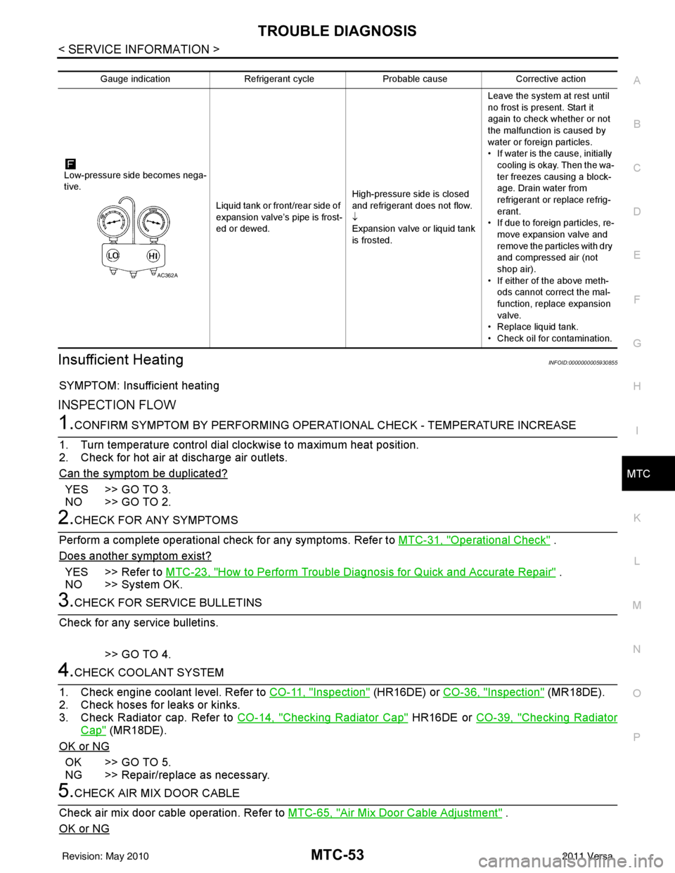
Gauge indication Refrigerant cycleProbable causeCorrective action
Low-pressure side becomes nega-
tive. Liquid tank or front/rear side of
expansion valve’s pipe is frost-
ed or dewed.High-pressure side is closed
and refrigerant does not flow.
↓
Expansion valve or liquid tank
is frosted.Leave the system at rest until
no frost is present. Start it
again to check whether or not
the malfunction is caused by
water or foreign particles.
• If water is the cause, initially
cooling is okay. Then the wa-
ter freezes causing a block-
age. Drain water from
refrigerant or replace refrig-
erant.
• If due to foreign particles, re-
move expansion valve and
remove the particles with dry
and compressed air (not
shop air).
• If either of the above meth- ods cannot correct the mal-
function, replace expansion
valve.
• Replace liquid tank.
• Check oil for contamination.
AC362A
Revision: May 2010 2011 Versa
Page 3376 of 3787
MTC-60
< SERVICE INFORMATION >
A/C UNIT ASSEMBLY
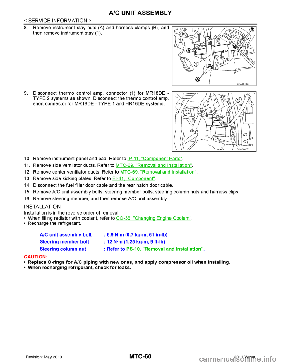
8. Remove instrument stay nuts (A) and harness clamps (B), andthen remove instrument stay (1).
9. Disconnect thermo control amp. connector (1) for MR18DE - TYPE 2 systems as shown. Di sconnect the thermo control amp.
short connector for MR18DE - TYPE 1 and HR16DE systems.
10. Remove instrument panel and pad. Refer to IP-11, "
Component Parts".
11. Remove side ventilator ducts. Refer to MTC-69, "
Removal and Installation".
12. Remove center ventilator ducts. Refer to MTC-69, "
Removal and Installation".
13. Remove side kicking plates. Refer to EI-41, "
Component".
14. Disconnect the fuel filler door cable and the rear hatch door cable.
15. Remove A/C unit assembly bolts, steering member bolts, steering column nuts and harness clips.
16. Remove steering member, and then remove A/C unit assembly.
INSTALLATION
Installation is in the reverse order of removal.
• When filling radiator with coolant, refer to CO-36, "
Changing Engine Coolant".
• Recharge the refrigerant.
CAUTION:
• Replace O-rings for A/C piping with new ones, and apply compressor oil when installing.
• When recharging refrigerant, check for leaks.
SJIA0646E
SJIA0647E
A/C unit assembly bolt : 6.9 N·m (0.7 kg-m, 61 in-lb)
Steering member bolt : 12 N·m (1.25 kg-m, 9 ft-lb)
Steering column nut : Refer to PS-10, "
Removal and Installation".
Revision: May 2010 2011 Versa
Page 3405 of 3787
REFRIGERANT LINESMTC-89
< SERVICE INFORMATION >
C
DE
F
G H
I
K L
M A
B
MTC
N
O P
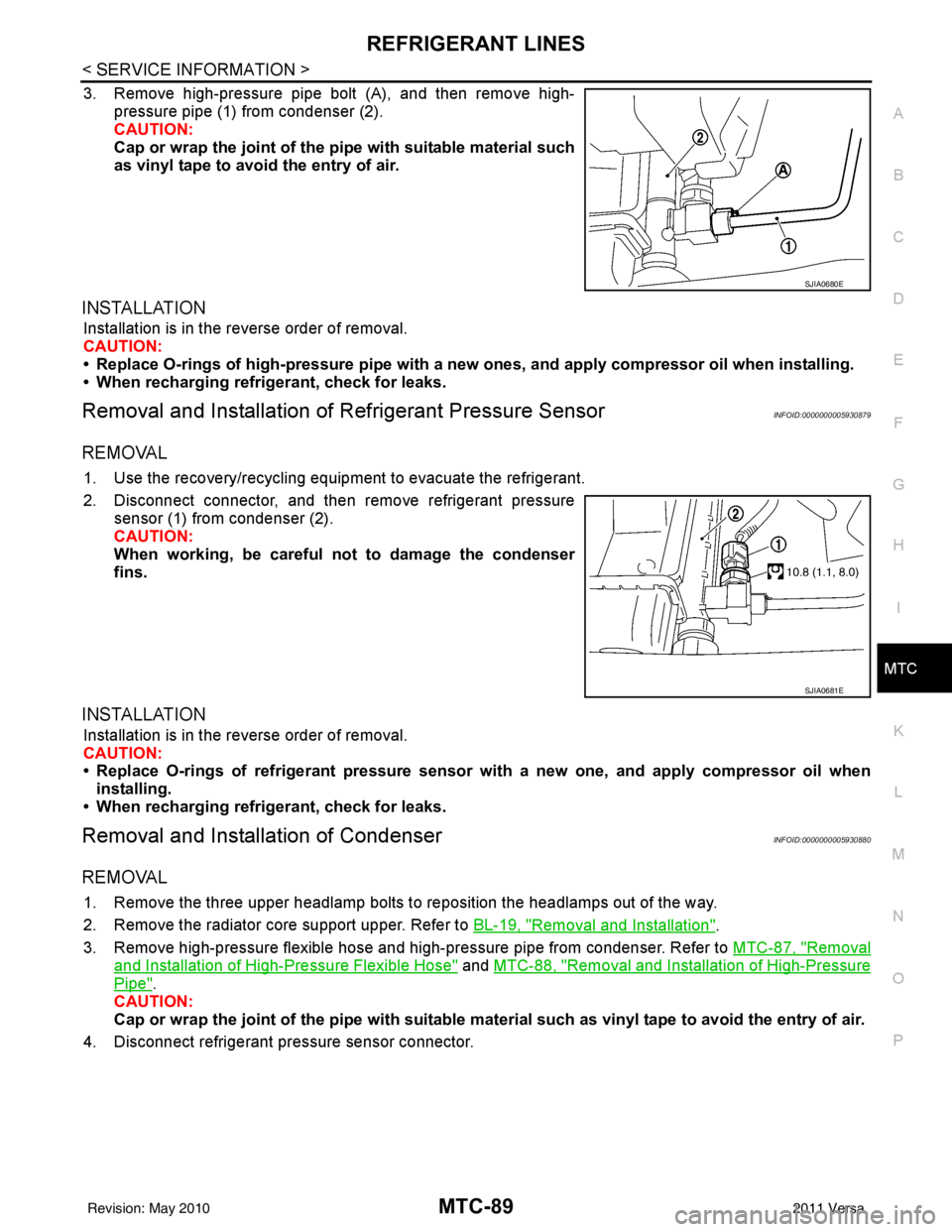
3. Remove high-pressure pipe bolt (A), and then remove high- pressure pipe (1) from condenser (2).
CAUTION:
Cap or wrap the joint of the pi pe with suitable material such
as vinyl tape to avoid the entry of air.
INSTALLATION
Installation is in the reverse order of removal.
CAUTION:
• Replace O-rings of high-pressure pipe with a new ones, and apply compr essor oil when installing.
• When recharging refrigerant, check for leaks.
Removal and Installation of Refrigerant Pressure SensorINFOID:0000000005930879
REMOVAL
1. Use the recovery/recycling equipment to evacuate the refrigerant.
2. Disconnect connector, and then remove refrigerant pressure
sensor (1) from condenser (2).
CAUTION:
When working, be careful not to damage the condenser
fins.
INSTALLATION
Installation is in the reverse order of removal.
CAUTION:
• Replace O-rings of refrigerant pressure senso r with a new one, and apply compressor oil when
installing.
• When recharging refrigerant, check for leaks.
Removal and Installation of CondenserINFOID:0000000005930880
REMOVAL
1. Remove the three upper headlamp bolts to reposition the headlamps out of the way.
2. Remove the radiator core support upper. Refer to BL-19, "
Removal and Installation".
3. Remove high-pressure flexible hose and high-pressure pipe from condenser. Refer to MTC-87, "
Removal
and Installation of High-Pressure Flexible Hose" and MTC-88, "Removal and Installation of High-Pressure
Pipe".
CAUTION:
Cap or wrap the joint of the pipe with suitable ma terial such as vinyl tape to avoid the entry of air.
4. Disconnect refrigerant pr essure sensor connector.
SJIA0680E
SJIA0681E
Revision: May 2010 2011 Versa