2011 NISSAN TIIDA oil level
[x] Cancel search: oil levelPage 2707 of 3787
PRECAUTIONSGI-3
< SERVICE INFORMATION >
C
DE
F
G H
I
J
K L
M B
GI
N
O P
2. Use the Intelligent Key or mechanical key to turn the ignition switch to the ″ACC ″ position. At this time, the
steering lock will be released.
3. Disconnect both battery cables. The steering lock will remain released and the steering wheel can be
rotated.
4. Perform the necessary repair operation.
5. When the repair work is completed, return the ignition switch to the ″LOCK ″ position before connecting
the battery cables. (At this time, the steering lock mechanism will engage.)
6. Perform a self-diagnosis check of al l control units using CONSULT-III.
General PrecautionINFOID:0000000005929711
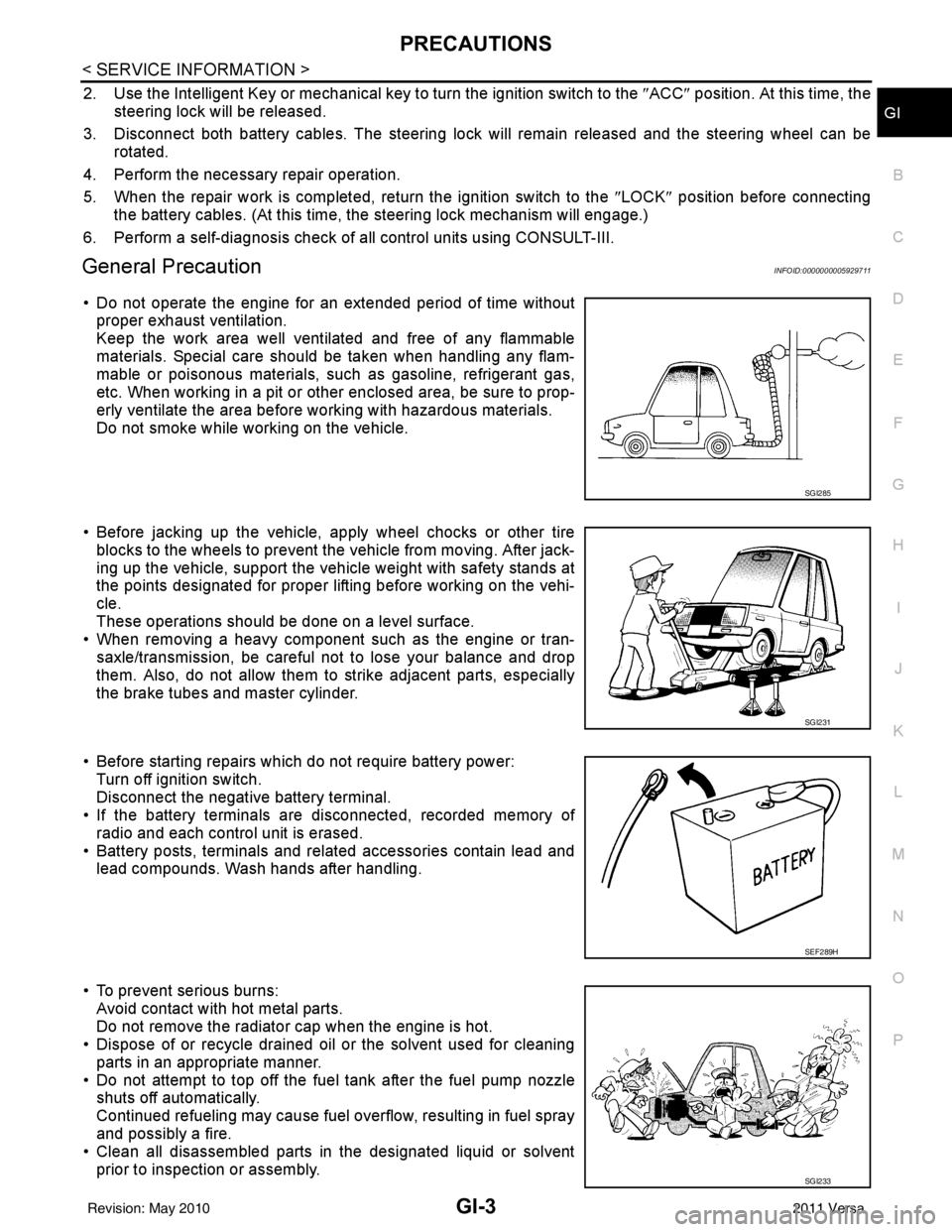
• Do not operate the engine for an extended period of time without
proper exhaust ventilation.
Keep the work area well ventilated and free of any flammable
materials. Special care should be taken when handling any flam-
mable or poisonous materials, such as gasoline, refrigerant gas,
etc. When working in a pit or ot her enclosed area, be sure to prop-
erly ventilate the area before working with hazardous materials.
Do not smoke while working on the vehicle.
• Before jacking up the vehicle, apply wheel chocks or other tire blocks to the wheels to prevent t he vehicle from moving. After jack-
ing up the vehicle, support the vehicle weight with safety stands at
the points designated for proper lifting before working on the vehi-
cle.
These operations should be done on a level surface.
• When removing a heavy component such as the engine or tran-
saxle/transmission, be careful not to lose your balance and drop
them. Also, do not allow them to strike adjacent parts, especially
the brake tubes and master cylinder.
• Before starting repairs which do not require battery power: Turn off ignition switch.
Disconnect the negative battery terminal.
• If the battery terminals are disconnected, recorded memory of
radio and each control unit is erased.
• Battery posts, terminals and related accessories contain lead and lead compounds. Wash hands after handling.
• To prevent serious burns: Avoid contact with hot metal parts.
Do not remove the radiator cap when the engine is hot.
• Dispose of or recycle drained oil or the solvent used for cleaning
parts in an appropriate manner.
• Do not attempt to top off the fuel tank after the fuel pump nozzle shuts off automatically.
Continued refueling may cause fuel overflow, resulting in fuel spray
and possibly a fire.
• Clean all disassembled parts in the designated liquid or solvent
prior to inspection or assembly.
SGI285
SGI231
SEF289H
SGI233
Revision: May 2010 2011 Versa
Page 2708 of 3787
GI-4
< SERVICE INFORMATION >
PRECAUTIONS
• Replace oil seals, gaskets, packings, O-rings, locking washers, cotter pins, self-locking nuts, etc. with new
ones.
• Replace inner and outer races of tapered roller bearings and needle bearings as a set.
• Arrange the disassembled parts in accordance with their assembled locations and sequence.
• Do not touch the terminals of electrical com ponents which use microcomputers (such as ECM).
Static electricity may damage internal electronic components.
• After disconnecting vacuum or air hoses, atta ch a tag to indicate the proper connection.
• Use only the fluids and lubricants specified in this manual.
• Use approved bonding agent, sealants or their equivalents when required.
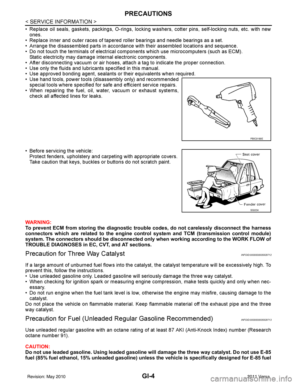
• Use hand tools, power tools (disassembly only) and recommended special tools where specified for safe and efficient service repairs.
• When repairing the fuel, oil, water, vacuum or exhaust systems, check all affected lines for leaks.
• Before servicing the vehicle: Protect fenders, upholstery and carpeting with appropriate covers.
Take caution that keys, buckles or buttons do not scratch paint.
WARNING:
To prevent ECM from storing the diagnostic tro uble codes, do not carelessly disconnect the harness
connectors which are related to the engine control system and TCM (transmission control module)
system. The connectors should be disconnected only when working according to the WORK FLOW of
TROUBLE DIAGNOSES in EC, CVT, and AT sections.
Precaution for Three Way CatalystINFOID:0000000005929712
If a large amount of unburned fuel flows into the catalyst , the catalyst temperature will be excessively high. To
prevent this, follow the instructions.
• Use unleaded gasoline only. Leaded gasoline will seriously damage the three way catalyst.
• When checking for ignition spark or measuring engine compression, make tests quickly and only when nec- essary.
• Do not run engine when the fuel tank level is low, otherwise the engine may misfire, causing damage to the
catalyst.
Do not place the vehicle on flammable material. Keep flammable material off the exhaust pipe and the three
way catalyst.
Precaution for Fuel (Unleade d Regular Gasoline Recommended)INFOID:0000000005929713
Use unleaded regular gasoline with an octane rating of at least 87 AKI (Anti-Knock Index) number (Research
octane number 91).
CAUTION:
Do not use leaded gasoline. Using leaded gasoline will damage the three way catalyst. Do not use E-85
fuel (85% fuel ethanol, 15% unleaded gasoline) unless the vehicle is specifically designed for E-85 fuel
PBIC0190E
SGI234
Revision: May 2010 2011 Versa
Page 2742 of 3787
GI-38
< SERVICE INFORMATION >
LIFTING POINT
LIFTING POINT
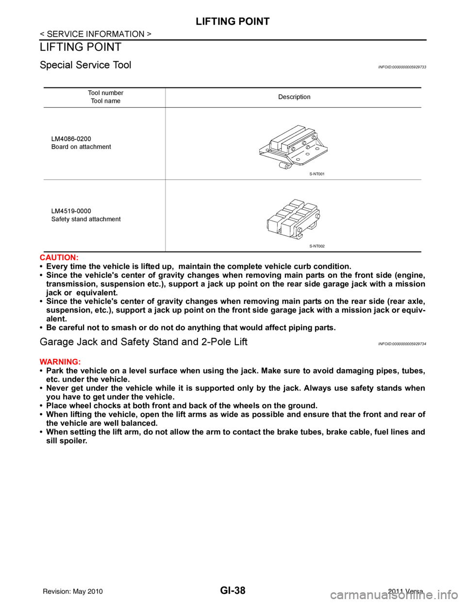
Special Service ToolINFOID:0000000005929733
CAUTION:
• Every time the vehicle is lifted up, maintain the complete vehicle curb condition.
• Since the vehicle's center of gravity changes when removing main parts on the front side (engine,
transmission, suspension etc.), support a jack up point on the rear side garage jack with a mission
jack or equivalent.
• Since the vehicle's center of gravity changes when removing main parts on the rear side (rear axle,
suspension, etc.), support a jack up point on the front side garage jack with a mission jack or equiv-
alent.
• Be careful not to smash or do not do an ything that would affect piping parts.
Garage Jack and Safety Stand and 2-Pole LiftINFOID:0000000005929734
WARNING:
• Park the vehicle on a level surface when using the jack. Make sure to avoid damaging pipes, tubes,
etc. under the vehicle.
• Never get under the vehicle while it is supported only by the jack. Always use safety stands when you have to get under the vehicle.
• Place wheel chocks at both front an d back of the wheels on the ground.
• When lifting the vehicle, open the lift arms as wid e as possible and ensure that the front and rear of
the vehicle are well balanced.
• When setting the lift arm, do not allow the arm to contact the brake tubes, brake cable, fuel lines and
sill spoiler.
Tool number
Tool name Description
LM4086-0200
Board on attachment
LM4519-0000
Safety stand attachment
S-NT001
S-NT002
Revision: May 2010 2011 Versa
Page 2874 of 3787
![NISSAN TIIDA 2011 Service Repair Manual LAN-28
< SERVICE INFORMATION >[CAN]
CAN COMMUNICATION SYSTEM
*1: A/T models
*2: CVT models
*3: Models with VDC
*4: Models for Canada
*5: Models for USA
*6: Models without ABS
NOTE:
CAN data of the air NISSAN TIIDA 2011 Service Repair Manual LAN-28
< SERVICE INFORMATION >[CAN]
CAN COMMUNICATION SYSTEM
*1: A/T models
*2: CVT models
*3: Models with VDC
*4: Models for Canada
*5: Models for USA
*6: Models without ABS
NOTE:
CAN data of the air](/manual-img/5/57396/w960_57396-2873.png)
LAN-28
< SERVICE INFORMATION >[CAN]
CAN COMMUNICATION SYSTEM
*1: A/T models
*2: CVT models
*3: Models with VDC
*4: Models for Canada
*5: Models for USA
*6: Models without ABS
NOTE:
CAN data of the air bag diagnosis sensor unit is not used by usual service work, thus it is omitted.
KEY warning lamp signal
T R
LOCK warning lamp signal T R
Panic alarm request signal RT
Fuel level sensor signal RT
Overdrive control switch signal TR R
Parking brake switch signal
*3TR
Stop lamp switch signal T R R
Vehicle speed signal RRRR T
RRR T R
R
*6T*6
Steering angle sensor signal*3TR
ABS warning lamp signal RT
Brake warning lamp signal RT
SLIP indicator lamp signal
*3RT
VDC OFF indicator lamp signal
*3RT
VDC warning lamp signal
*3RT
A/T check indicator signal RT
A/T self-diagnosis signal R T
Input speed signal R T
OD OFF indicator signal RT
Output shaft revolution signal R T T
Shift position indicator signal R
R
*3TT
CVT self-diagnosis signal R T
Input shaft revolution signal R T
OD OFF indicator signal RT
Front wiper stop position signal R T
High beam status signal R T
Low beam status signal R T
Oil pressure switch signal R RR T
Rear window defogger control signal R T
Signal name/Connecting unit
ECM
BCM
EPS
I-KEY M&A
STRG ABS
TCM
*1
TCM
*2
IPDM-E
Revision: May 2010 2011 Versa
Page 3055 of 3787
HEADLAMP (FOR USA)LT-23
< SERVICE INFORMATION >
C
DE
F
G H
I
J
L
M A
B
LT
N
O P
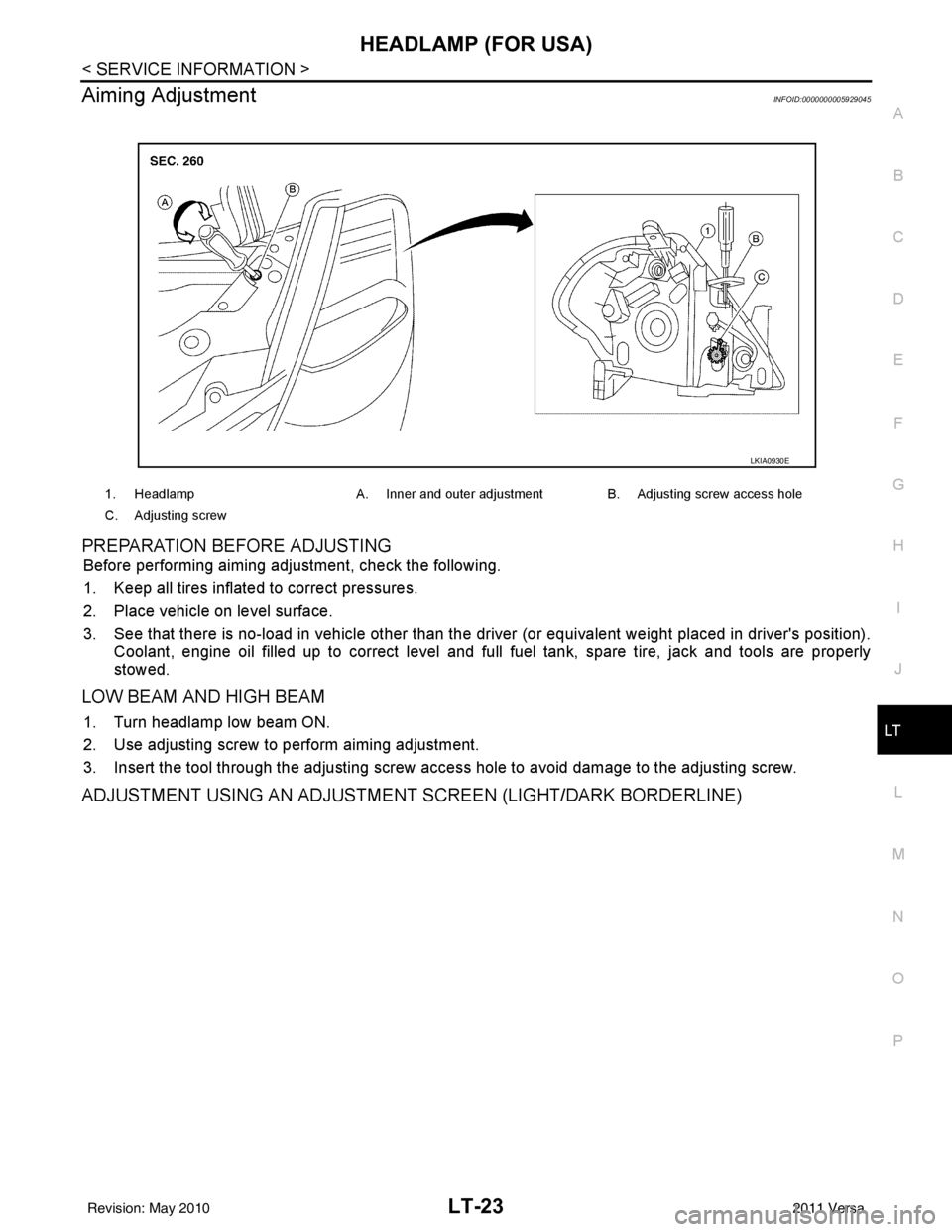
Aiming AdjustmentINFOID:0000000005929045
PREPARATION BEFORE ADJUSTING
Before performing aiming adjustment, check the following.
1. Keep all tires inflated to correct pressures.
2. Place vehicle on level surface.
3. See that there is no-load in vehicle other than the driver (or equivalent weight placed in driver's position). Coolant, engine oil filled up to correct level and full fuel tank, spare tire, jack and tools are properly
stowed.
LOW BEAM AND HIGH BEAM
1. Turn headlamp low beam ON.
2. Use adjusting screw to perform aiming adjustment.
3. Insert the tool through the adjusting screw acce ss hole to avoid damage to the adjusting screw.
ADJUSTMENT USING AN ADJUSTMENT SCREEN (LIGHT/DARK BORDERLINE)
1. HeadlampA. Inner and outer adjustment B. Adjusting screw access hole
C. Adjusting screw
LKIA0930E
Revision: May 2010 2011 Versa
Page 3069 of 3787
HEADLAMP (FOR CANADA) - DAYTIME LIGHT SYSTEM -
LT-37
< SERVICE INFORMATION >
C
D E
F
G H
I
J
L
M A
B
LT
N
O P
Aiming AdjustmentINFOID:0000000005929061
PREPARATION BEFORE ADJUSTING
Before performing aiming adjustment, check the following.
1. Keep all tires inflated to correct pressures.
2. Place vehicle on level surface.
3. Set that there is no-load in vehicle other than the driv er (or equivalent weight placed in driver's position).
Coolant, engine oil filled up to correct level and full fuel tank, spare tire, jack and tools are properly
stowed.
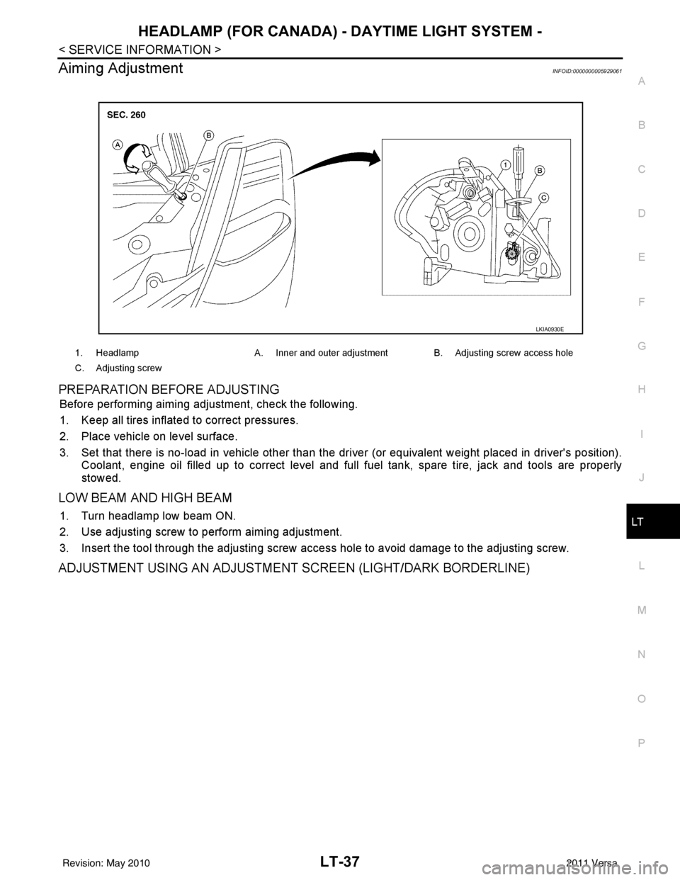
LOW BEAM AND HIGH BEAM
1. Turn headlamp low beam ON.
2. Use adjusting screw to perform aiming adjustment.
3. Insert the tool through the adjusting screw access hole to avoid damage to the adjusting screw.
ADJUSTMENT USING AN ADJUSTMENT SCREEN (LIGHT/DARK BORDERLINE)
1. Headlamp A. Inner and outer adjustment B. Adjusting screw access hole
C. Adjusting screw
LKIA0930E
Revision: May 2010 2011 Versa
Page 3080 of 3787
LT-48
< SERVICE INFORMATION >
FRONT FOG LAMP
1. Check continuity between front fog lamp harness connector and
ground.
OK or NG
OK >> Replace IPDM E/R. Refer to PG-28, "Removal and
Installation of IPDM E/R" .
NG >> Repair harness or connector.
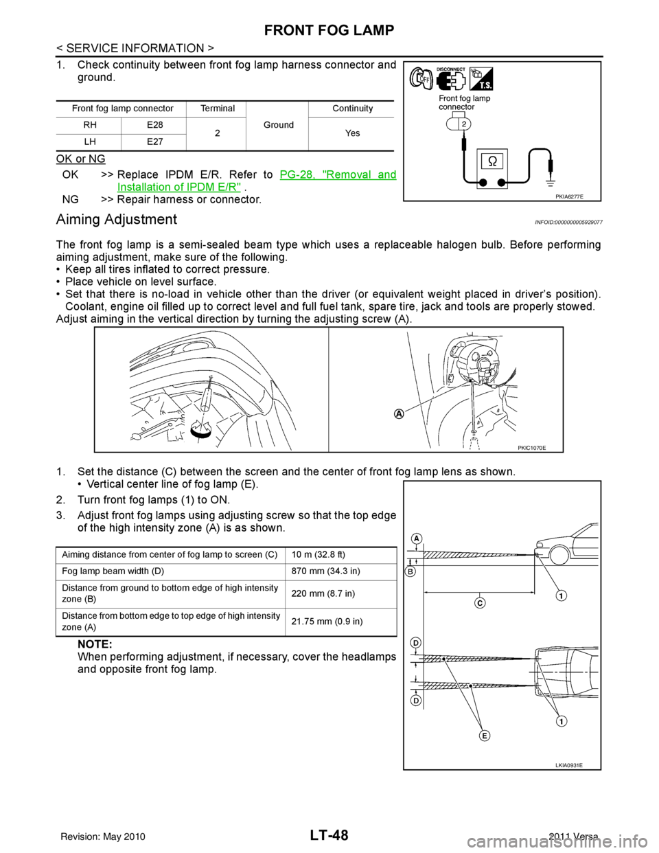
Aiming AdjustmentINFOID:0000000005929077
The front fog lamp is a semi-sealed beam type which uses a replaceable halogen bulb. Before performing
aiming adjustment, make sure of the following.
• Keep all tires inflated to correct pressure.
• Place vehicle on level surface.
• Set that there is no-load in vehicle other than the driv er (or equivalent weight placed in driver’s position).
Coolant, engine oil filled up to correct level and full fuel tank, spare tire, jack and tools are properly stowed.
Adjust aiming in the vertical direct ion by turning the adjusting screw (A).
1. Set the distance (C) between the screen and the center of front fog lamp lens as shown. • Vertical center line of fog lamp (E).
2. Turn front fog lamps (1) to ON.
3. Adjust front fog lamps using adjusting screw so that the top edge of the high intensity zone (A) is as shown.
NOTE:
When performing adjustment, if necessary, cover the headlamps
and opposite front fog lamp.
Front fog lamp connector Terminal
Ground Continuity
RH E28
2Y es
LH E27
PKIA6277E
PKIC1070E
Aiming distance from center of fog lamp to screen (C) 10 m (32.8 ft)
Fog lamp beam width (D) 870 mm (34.3 in)
Distance from ground to bottom edge of high intensity
zone (B) 220 mm (8.7 in)
Distance from bottom edge to top edge of high intensity
zone (A) 21.75 mm (0.9 in)
LKIA0931E
Revision: May 2010
2011 Versa
Page 3155 of 3787
![NISSAN TIIDA 2011 Service Repair Manual ENGINE OILLU-7
< ON-VEHICLE MAINTENANCE > [HR16DE]
C
D
E
F
G H
I
J
K L
M A
LU
NP
O
ON-VEHICLE MAINTENANCE
ENGINE OIL
InspectionINFOID:0000000005928687
ENGINE OIL LEVEL
NOTE:
Park vehicle on a level su NISSAN TIIDA 2011 Service Repair Manual ENGINE OILLU-7
< ON-VEHICLE MAINTENANCE > [HR16DE]
C
D
E
F
G H
I
J
K L
M A
LU
NP
O
ON-VEHICLE MAINTENANCE
ENGINE OIL
InspectionINFOID:0000000005928687
ENGINE OIL LEVEL
NOTE:
Park vehicle on a level su](/manual-img/5/57396/w960_57396-3154.png)
ENGINE OILLU-7
< ON-VEHICLE MAINTENANCE > [HR16DE]
C
D
E
F
G H
I
J
K L
M A
LU
NP
O
ON-VEHICLE MAINTENANCE
ENGINE OIL
InspectionINFOID:0000000005928687
ENGINE OIL LEVEL
NOTE:
Park vehicle on a level surface, wait 10 minutes and check the engine oil level.
1. Pull out oil level gauge and wipe it clean.
2. Insert oil level gauge and make sure the engine oil level is within
the range (A) as shown.
3. If it is out of range, adjust it.
ENGINE OIL APPEARANCE
• Check engine oil for white milky appearance or excessive contamination.
• If engine oil becomes white, it is highly probable t hat it is contaminated with engine coolant. Repair or
replace damaged parts.
ENGINE OIL LEAKAGE
Check for engine oil leakage around the following areas:
• Oil pan (upper and lower)
• Oil pan drain plug
• Oil pressure switch
• Oil filter
• Intake valve timing control solenoid valve
• Front cover
• Mating surface between cylinder head and camshaft bracket
• Mating surface between cylinder block and cylinder head
• Mating surface between cylinder head and rocker cover
• Crankshaft oil seals (front and rear)
• Oil filter (for intake valve timing control)
OIL PRESSURE CHECK
WARNING:
• Be careful not to burn yoursel f, as engine oil may be hot.
• For engine oil pressure check the transaxle should be in “Park position” (A/T models) or “Neutral
position” (M/T models), and apply the parking brake securely.
1. Check engine oil level.
2. Remove engine under cover. Refer to EI-15, "
Removal and Installation".
3. Disconnect harness connector at oil pressure switch (2), and remove oil pressure switch (2) from the cylinder block (1) using
suitable tool.
CAUTION:
Never drop or shock oil pressure switch.
JPBIA0554ZZ
PBIC3817E
Revision: May 2010 2011 Versa