2011 NISSAN TIIDA oil level
[x] Cancel search: oil levelPage 2575 of 3787
![NISSAN TIIDA 2011 Service Repair Manual OIL SEALEM-185
< SERVICE INFORMATION > [MR18DE]
C
D
E
F
G H
I
J
K L
M A
EM
NP
O
• Install rear oil seal (1) to the position as shown.
NOTE:
The standard surface of the dimens
ion is the rear end sur NISSAN TIIDA 2011 Service Repair Manual OIL SEALEM-185
< SERVICE INFORMATION > [MR18DE]
C
D
E
F
G H
I
J
K L
M A
EM
NP
O
• Install rear oil seal (1) to the position as shown.
NOTE:
The standard surface of the dimens
ion is the rear end sur](/manual-img/5/57396/w960_57396-2574.png)
OIL SEALEM-185
< SERVICE INFORMATION > [MR18DE]
C
D
E
F
G H
I
J
K L
M A
EM
NP
O
• Install rear oil seal (1) to the position as shown.
NOTE:
The standard surface of the dimens
ion is the rear end surface of
cylinder block.
3. Installation of the remaining components is in the reverse order of removal.
InspectionINFOID:0000000006413292
INSPECTION AFTER INSTALLATION
• Before starting engine, check oil/fluid levels incl uding engine coolant and engine oil. If less than required
quantity, fill to the specified level. Refer to MA-14, "
Fluids and Lubricants".
• Use procedure below to check for fuel leakage.
• Turn ignition switch ON (with engine stopped). With fuel pressure applied to fuel piping, check for fuel leak-
age at connection points.
• Start engine. With engine speed increased, check again for fuel leakage at connection points.
• Run engine to check for unusual noise and vibration.
• Warm up engine thoroughly to make sure there is no leak age of fuel, exhaust gas, or any oils/fluids including
engine oil and engine coolant.
• Bleed air from passages in lines and hoses, such as in cooling system.
• After cooling down engine, again check oil/fluid levels including engine oil and engine coolant. Refill to spec- ified level, if necessary.
• Summary of the inspection items:
*Power steering fluid, brake fluid, etc. A : Rear end surface of cylinder block
PBIC3761E
Item
Before starting engine Engine runningAfter engine stopped
Engine coolant LevelLeakage Level
Engine oil LevelLeakage Level
Transmission/
transaxle fluid A/T and CVT Models
LeakageLevel/Leakage Leakage
M/T Models Level/Leakage LeakageLevel/Leakage
Other oils and fluids* LevelLeakage Level
Fuel LeakageLeakageLeakage
Exhaust gas —Leakage —
Revision: May 2010 2011 Versa
Page 2577 of 3787
![NISSAN TIIDA 2011 Service Repair Manual CYLINDER HEADEM-187
< SERVICE INFORMATION > [MR18DE]
C
D
E
F
G H
I
J
K L
M A
EM
NP
O
• If the engine speed is out of the specified range, check battery liquid for proper gravity. Check engine
speed NISSAN TIIDA 2011 Service Repair Manual CYLINDER HEADEM-187
< SERVICE INFORMATION > [MR18DE]
C
D
E
F
G H
I
J
K L
M A
EM
NP
O
• If the engine speed is out of the specified range, check battery liquid for proper gravity. Check engine
speed](/manual-img/5/57396/w960_57396-2576.png)
CYLINDER HEADEM-187
< SERVICE INFORMATION > [MR18DE]
C
D
E
F
G H
I
J
K L
M A
EM
NP
O
• If the engine speed is out of the specified range, check battery liquid for proper gravity. Check engine
speed again with normal battery gravity.
• If compression pressure is below minimum value, check valve clearances and parts associated with
combustion chamber (Valve, valve seat, piston, pi ston ring, cylinder bore, cylinder head, cylinder head
gasket). After the checking, measure the compression pressure again.
• If one cylinder has low compression pressure, pour small amount of engine oil into the spark plug hole
of the cylinder to re-check it for compression.
- If the added engine oil improves the compression, piston rings may be worn out or damaged. Check pis- ton rings and replace if necessary.
- If the compression pressure remains at low level despite the addition of engine oil, valves may be mal- functioning. Check valves for damage. Replace valve or valve seat accordingly.
• If two adjacent cylinders have respectively low compression pressure and their compression remains low even after the addition of engine oil, cylinder head gasket is leaking. In such a case, replace cylinder
head gasket.
9. After inspection is completed, install removed parts.
10. Start the engine, and confirm that the engine runs smoothly.
11. Perform trouble diagnosis. If DTC appears, erase it. Refer to EC-585, "
Trouble Diagnosis Introduction".
InspectionINFOID:0000000006413294
INSPECTION AFTER INSTALLATION
• Before starting engine, check oil/fluid levels including engine coolant and engine oil. If less than required
quantity, fill to the specified level. Refer to MA-14, "
Fluids and Lubricants".
• Use procedure below to check for fuel leakage.
• Turn ignition switch ON (with engine stopped). With fuel pressure applied to fuel piping, check for fuel leak-
age at connection points.
• Start engine. With engine speed increased, check again for fuel leakage at connection points.
• Run engine to check for unusual noise and vibration.
• Warm up engine thoroughly to make sure there is no leak age of fuel, exhaust gas, or any oils/fluids including
engine oil and engine coolant.
• Bleed air from passages in lines and hoses, such as in cooling system.
• After cooling down engine, again check oil/fluid levels including engine oil and engine coolant. Refill to spec- ified level, if necessary.
• Summary of the inspection items:
*Power steering fluid, brake fluid, etc. Item
Before starting engine Engine runningAfter engine stopped
Engine coolant LevelLeakage Level
Engine oil LevelLeakage Level
Transmission/
transaxle fluid A/T and CVT Models
LeakageLevel/Leakage Leakage
M/T Models Level/Leakage LeakageLevel/Leakage
Other oils and fluids* LevelLeakage Level
Fuel LeakageLeakageLeakage
Exhaust gas —Leakage —
Revision: May 2010 2011 Versa
Page 2590 of 3787
![NISSAN TIIDA 2011 Service Repair Manual EM-200
< SERVICE INFORMATION >[MR18DE]
ENGINE ASSEMBLY
35. Separate the engine and the transaxle and mount the engine on a suitable engine stand. Refer to
AT-233
(A/T models), CVT-180, "Removal and I NISSAN TIIDA 2011 Service Repair Manual EM-200
< SERVICE INFORMATION >[MR18DE]
ENGINE ASSEMBLY
35. Separate the engine and the transaxle and mount the engine on a suitable engine stand. Refer to
AT-233
(A/T models), CVT-180, "Removal and I](/manual-img/5/57396/w960_57396-2589.png)
EM-200
< SERVICE INFORMATION >[MR18DE]
ENGINE ASSEMBLY
35. Separate the engine and the transaxle and mount the engine on a suitable engine stand. Refer to
AT-233
(A/T models), CVT-180, "Removal and Installation" (CVT models) or MT-61, "Removal and Installation"
(M/T models).
INSTALLATION
Installation is in the reverse order of removal.
Note the following during installation:
• When installation directions are specified, install parts according to the directions. Refer to EM-197, "
Com-
ponent".
• Do not allow engine oil to get on engine mounting insulator. Be careful not to damage engine mounting insu-
lator.
• Prior to installing the upper torque rod, apply a light coat of silicone lubricant (A) to the washer facing side of the bushing inner tube as
shown.
NOTE:
• Apply silicone lubricant (A) by dabbing the outward facing tubesurface with a sponge or suitable tool.
• Do not apply excess lubricant.
• Make sure that each mounting insulator is seated properly, and tighten nuts and bolts.
• Tighten engine mounting insulator (RH) bolts in the numerical order shown.
INSPECTION AFTER INSTALLATION
• Before starting engine, check oil/fluid levels incl uding engine coolant and engine oil. If less than required
quantity, fill to the specified level. Refer to MA-14, "
Fluids and Lubricants".
• Use procedure below to check for fuel leakage.
• Turn ignition switch ON (with engine stopped). With fuel pressure applied to fuel piping, check for fuel leak- age at connection points.
• Start engine. With engine speed increased, che ck again for fuel leakage at connection points.
• Run engine to check for unusual noise and vibration.
• Warm up engine thoroughly to make sure there is no leakage of fuel, exhaust gas, or any oils/fluids including
engine oil and engine coolant.
• Bleed air from passages in lines and hoses, such as in cooling system.
• After cooling down engine, again check oil/fluid levels including engine oil and engine coolant. Refill to spec- ified level, if necessary.
• Summary of the inspection items:
: Vehicle front
LBIA0470E
: Vehicle front
WBIA0785E
Item Before starting engine Engine runningAfter engine stopped
Engine coolant LevelLeakage Level
Engine oil LevelLeakage Level
Transmission/
transaxle fluid A/T and CVT Models
LeakageLevel/Leakage Leakage
M/T Models Level/Leakage LeakageLevel/Leakage
Revision: May 2010 2011 Versa
Page 2591 of 3787
![NISSAN TIIDA 2011 Service Repair Manual ENGINE ASSEMBLYEM-201
< SERVICE INFORMATION > [MR18DE]
C
D
E
F
G H
I
J
K L
M A
EM
NP
O*Power steering fluid, brake fluid, etc.
Other oils and fluids*
LevelLeakage Level
Fuel LeakageLeakageLeakage
Exha NISSAN TIIDA 2011 Service Repair Manual ENGINE ASSEMBLYEM-201
< SERVICE INFORMATION > [MR18DE]
C
D
E
F
G H
I
J
K L
M A
EM
NP
O*Power steering fluid, brake fluid, etc.
Other oils and fluids*
LevelLeakage Level
Fuel LeakageLeakageLeakage
Exha](/manual-img/5/57396/w960_57396-2590.png)
ENGINE ASSEMBLYEM-201
< SERVICE INFORMATION > [MR18DE]
C
D
E
F
G H
I
J
K L
M A
EM
NP
O*Power steering fluid, brake fluid, etc.
Other oils and fluids*
LevelLeakage Level
Fuel LeakageLeakageLeakage
Exhaust gas —Leakage —
Revision: May 2010 2011 Versa
Page 2652 of 3787

FAX-10
< SERVICE INFORMATION >
FRONT DRIVE SHAFT
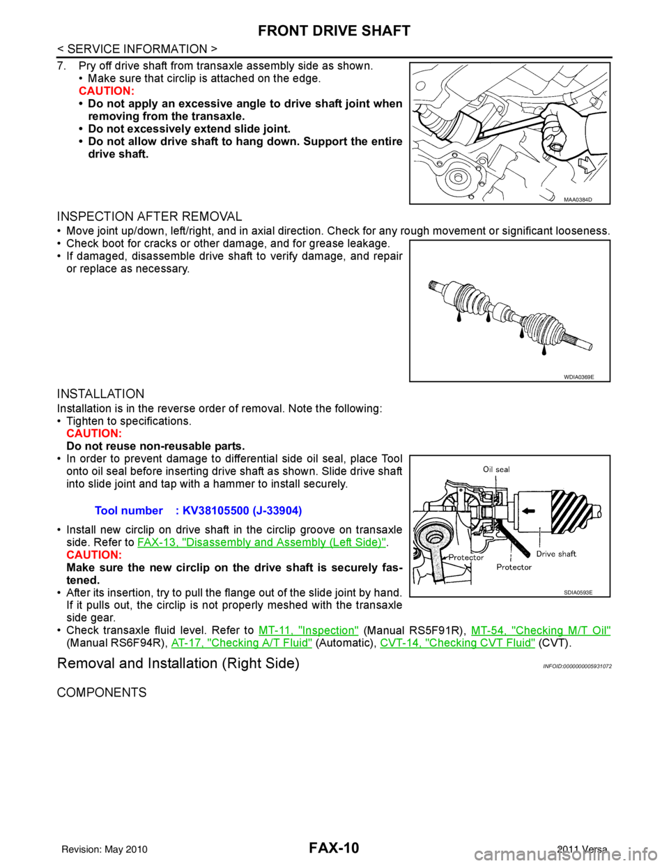
7. Pry off drive shaft from transaxle assembly side as shown.• Make sure that circlip is attached on the edge.
CAUTION:
• Do not apply an excessive angle to drive shaft joint when
removing from the transaxle.
• Do not excessively extend slide joint.
• Do not allow drive shaft to hang down. Support the entire
drive shaft.
INSPECTION AFTER REMOVAL
• Move joint up/down, left/right, and in axial direction. Check for any rough movement or significant looseness.
• Check boot for cracks or other damage, and for grease leakage.
• If damaged, disassemble drive shaft to verify damage, and repair or replace as necessary.
INSTALLATION
Installation is in the reverse order of removal. Note the following:
• Tighten to specifications.CAUTION:
Do not reuse non-reusable parts.
• In order to prevent damage to differential side oil seal, place Tool
onto oil seal before inserting drive shaft as shown. Slide drive shaft
into slide joint and tap with a hammer to install securely.
• Install new circlip on drive shaft in the circlip groove on transaxle side. Refer to FAX-13, "
Disassembly and Assembly (Left Side)".
CAUTION:
Make sure the new circlip on the drive shaft is securely fas-
tened.
• After its insertion, try to pull the flange out of the slide joint by hand. If it pulls out, the circlip is not properly meshed with the transaxle
side gear.
• Check transaxle fluid level. Refer to MT-11, "
Inspection" (Manual RS5F91R), MT-54, "Checking M/T Oil"
(Manual RS6F94R), AT-17, "Checking A/T Fluid" (Automatic), CVT-14, "Checking CVT Fluid" (CVT).
Removal and Installation (Right Side)INFOID:0000000005931072
COMPONENTS
MAA0384D
WDIA0369E
Tool number : KV38105500 (J-33904)
SDIA0593E
Revision: May 2010 2011 Versa
Page 2654 of 3787

FAX-12
< SERVICE INFORMATION >
FRONT DRIVE SHAFT
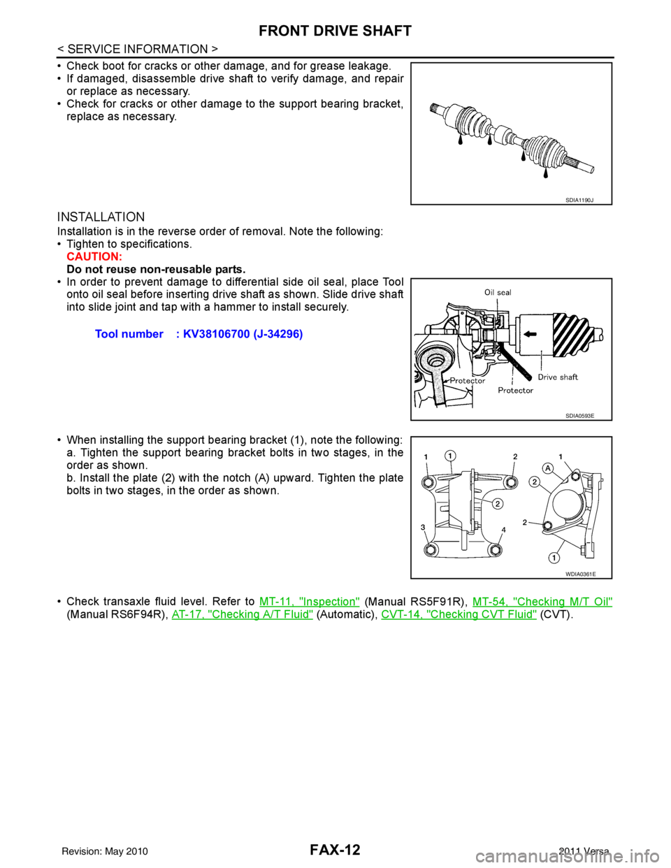
• Check boot for cracks or other damage, and for grease leakage.
• If damaged, disassemble drive shaft to verify damage, and repairor replace as necessary.
• Check for cracks or other damage to the support bearing bracket, replace as necessary.
INSTALLATION
Installation is in the reverse order of removal. Note the following:
• Tighten to specifications.CAUTION:
Do not reuse non-reusable parts.
• In order to prevent damage to differential side oil seal, place Tool onto oil seal before inserting drive shaft as shown. Slide drive shaft
into slide joint and tap with a hammer to install securely.
• When installing the support bearing bracket (1), note the following: a. Tighten the support bearing bracket bolts in two stages, in the
order as shown.
b. Install the plate (2) with the notch (A) upward. Tighten the plate
bolts in two stages, in the order as shown.
• Check transaxle fluid level. Refer to MT-11, "
Inspection" (Manual RS5F91R), MT-54, "Checking M/T Oil"
(Manual RS6F94R), AT-17, "Checking A/T Fluid" (Automatic), CVT-14, "Checking CVT Fluid" (CVT).
SDIA1190J
Tool number : KV38106700 (J-34296)
SDIA0593E
WDIA0361E
Revision: May 2010 2011 Versa
Page 2692 of 3787

FRONT SUSPENSION ASSEMBLYFSU-7
< SERVICE INFORMATION >
C
DF
G H
I
J
K L
M A
B
FSU
N
O P
FRONT SUSPENSION ASSEMBLY
On-Vehicle Inspection and ServiceINFOID:0000000005930898
Make sure the mounting conditions (looseness, back lash) of each component and component conditions
(wear, damage) are normal.
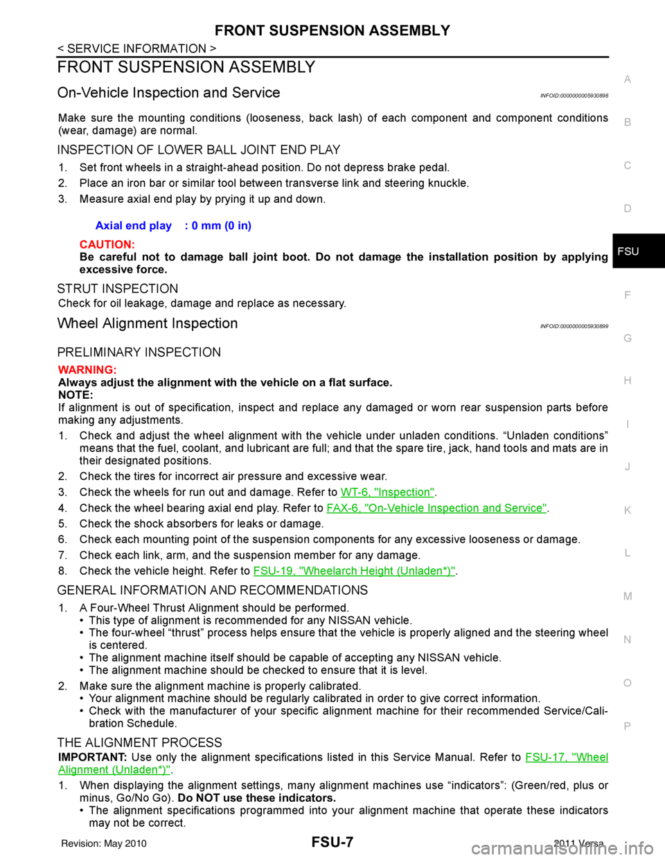
INSPECTION OF LOWER BALL JOINT END PLAY
1. Set front wheels in a straight-ahead position. Do not depress brake pedal.
2. Place an iron bar or similar tool between transverse link and steering knuckle.
3. Measure axial end play by prying it up and down.
CAUTION:
Be careful not to damage ball joint boot. Do not damage the installation position by applying
excessive force.
STRUT INSPECTION
Check for oil leakage, damage and replace as necessary.
Wheel Alignment InspectionINFOID:0000000005930899
PRELIMINARY INSPECTION
WARNING:
Always adjust the alignment with the vehicle on a flat surface.
NOTE:
If alignment is out of specification, inspect and replace any damaged or worn rear suspension parts before
making any adjustments.
1. Check and adjust the wheel alignment with the vehicle under unladen conditions. “Unladen conditions”
means that the fuel, coolant, and lubricant are full; and that the spare tire, jack, hand tools and mats are in
their designated positions.
2. Check the tires for incorrect air pressure and excessive wear.
3. Check the wheels for run out and damage. Refer to WT-6, "
Inspection".
4. Check the wheel bearing axial end play. Refer to FAX-6, "
On-Vehicle Inspection and Service".
5. Check the shock absorbers for leaks or damage.
6. Check each mounting point of the suspension components for any excessive looseness or damage.
7. Check each link, arm, and the suspension member for any damage.
8. Check the vehicle height. Refer to FSU-19, "
Wheelarch Height (Unladen*)".
GENERAL INFORMATION AND RECOMMENDATIONS
1. A Four-Wheel Thrust Alignment should be performed.
• This type of alignment is re commended for any NISSAN vehicle.
• The four-wheel “thrust” process helps ensure that the vehicle is properly aligned and the steering wheel
is centered.
• The alignment machine itself should be ca pable of accepting any NISSAN vehicle.
• The alignment machine should be checked to ensure that it is level.
2. Make sure the alignment machine is properly calibrated. • Your alignment machine should be regularly calibrated in order to give correct information.
• Check with the manufacturer of your specific a lignment machine for their recommended Service/Cali-
bration Schedule.
THE ALIGNMENT PROCESS
IMPORTANT: Use only the alignment specifications listed in this Service Manual. Refer to FSU-17, "Wheel
Alignment (Unladen*)".
1. When displaying the alignment settings, many alignm ent machines use “indicators”: (Green/red, plus or
minus, Go/No Go). Do NOT use these indicators.
• The alignment specifications programmed into your alignment machine that operate these indicators may not be correct.Axial end play : 0 mm (0 in)
Revision: May 2010
2011 Versa
Page 2697 of 3787

FSU-12
< SERVICE INFORMATION >
COIL SPRING AND STRUT
COIL SPRING AND STRUT
Removal and InstallationINFOID:0000000005930902
REMOVAL
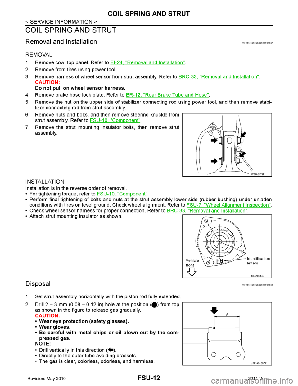
1. Remove cowl top panel. Refer to EI-24, "Removal and Installation".
2. Remove front tires using power tool.
3. Remove harness of wheel sensor from strut assembly. Refer to BRC-33, "
Removal and Installation".
CAUTION:
Do not pull on wheel sensor harness.
4. Remove brake hose lock plate. Refer to BR-12, "
Rear Brake Tube and Hose".
5. Remove the nut on the upper side of stabilizer connecting rod using power tool, and then remove stabi- lizer connecting rod from strut assembly.
6. Remove nuts and bolts, and then remove steering knuckle from strut assembly. Refer to FSU-10, "
Component".
7. Remove the strut mounting insulator bolts, then remove strut assembly.
INSTALLATION
Installation is in the reverse order of removal.
• For tightening torque, refer to FSU-10, "
Component".
• Perform final tightening of bolts and nuts at the strut assembly lower side (rubber bushing) under unladen
conditions with tires on level ground. Check wheel alignment. Refer to FSU-7, "
Wheel Alignment Inspection".
• Check wheel sensor harness for proper connection. Refer to BRC-33, "
Removal and Installation".
• Attach strut mounting insulator as shown.
DisposalINFOID:0000000005930903
1. Set strut assembly horizontally with the piston rod fully extended.
2. Drill 2 – 3 mm (0.08 – 0.12 in) hole at the position ( ) from top
as shown in the figure to release gas gradually.
CAUTION:
• Wear eye protection (safety glasses).
• Wear gloves.
• Be careful with metal chips or oil blown out by the com-pressed gas.
NOTE:
• Drill vertically in this direction ( ).
• Directly to the outer tube avoiding brackets.
• The gas is clear, colorless, odorless, and harmless.
WEIA0179E
MEIA0014E
JPEIA0160ZZ
Revision: May 2010 2011 Versa