2011 NISSAN TIIDA electrical wiring
[x] Cancel search: electrical wiringPage 3525 of 3787

RF-2
< PRECAUTION >
PRECAUTIONS
PRECAUTION
PRECAUTIONS
Precaution for Supplemental Restraint System (SRS) "AIR BAG" and "SEAT BELT
PRE-TENSIONER"
INFOID:0000000005929517
The Supplemental Restraint System such as “A IR BAG” and “SEAT BELT PRE-TENSIONER”, used along
with a front seat belt, helps to reduce the risk or severity of injury to the driver and front passenger for certain
types of collision. This system includes seat belt switch inputs and dual stage front air bag modules. The SRS
system uses the seat belt switches to determine the front air bag deployment, and may only deploy one front
air bag, depending on the severity of a collision and w hether the front occupants are belted or unbelted.
Information necessary to service the system safely is included in the SRS and SB section of this Service Man-
ual.
WARNING:
• To avoid rendering the SRS inopera tive, which could increase the risk of personal injury or death in
the event of a collision which would result in air bag inflation, all maintenance must be performed by
an authorized NISSAN/INFINITI dealer.
• Improper maintenance, including in correct removal and installation of the SRS, can lead to personal
injury caused by unintent ional activation of the system. For re moval of Spiral Cable and Air Bag
Module, see the SRS section.
• Do not use electrical test equipmen t on any circuit related to the SRS unless instructed to in this
Service Manual. SRS wiring harn esses can be identified by yellow and/or orange harnesses or har-
ness connectors.
PRECAUTIONS WHEN USING POWER TOOLS (AIR OR ELECTRIC) AND HAMMERS
WARNING:
• When working near the Airbag Diagnosis Sensor Unit or other Airbag System sensors with the Igni-
tion ON or engine running, DO NOT use air or electri c power tools or strike near the sensor(s) with a
hammer. Heavy vibration could activate the sensor( s) and deploy the air bag(s), possibly causing
serious injury.
• When using air or electric power tools or hammers , always switch the Ignition OFF, disconnect the
battery, and wait at least 3 minu tes before performing any service.
Precaution Necessary for Steering W heel Rotation After Battery Disconnect
INFOID:0000000005929518
NOTE:
• This Procedure is applied only to models with Intelligent Key system and NATS (NISSAN ANTI-THEFT SYS-
TEM).
• Remove and install all control units after disconnecting both battery cables with the ignition knob in the
″LOCK ″ position.
• Always use CONSULT-III to perform self-diagnosis as a part of each function inspection after finishing work.
If DTC is detected, perform trouble diagnosis according to self-diagnostic results.
For models equipped with the Intelligent Key system and NATS, an electrically controlled steering lock mech-
anism is adopted on the key cylinder.
For this reason, if the battery is disconnected or if the battery is discharged, the steering wheel will lock and
steering wheel rotation will become impossible.
If steering wheel rotation is required when battery pow er is interrupted, follow the procedure below before
starting the repair operation.
OPERATION PROCEDURE
1. Connect both battery cables. NOTE:
Supply power using jumper cables if battery is discharged.
2. Use the Intelligent Key or mechanical key to turn the ignition switch to the ″ACC ″ position. At this time, the
steering lock will be released.
3. Disconnect both battery cables. The steering lock will remain released and the steering wheel can be rotated.
4. Perform the necessary repair operation.
Revision: May 2010 2011 Versa
Page 3555 of 3787
RSU-2
< SERVICE INFORMATION >
PRECAUTIONS
SERVICE INFORMATION
PRECAUTIONS
Precaution for Supplemental Restraint System (SRS) "AIR BAG" and "SEAT BELT
PRE-TENSIONER"
INFOID:0000000005931079
The Supplemental Restraint System such as “A IR BAG” and “SEAT BELT PRE-TENSIONER”, used along
with a front seat belt, helps to reduce the risk or severity of injury to the driver and front passenger for certain
types of collision. This system includes seat belt switch inputs and dual stage front air bag modules. The SRS
system uses the seat belt switches to determine the front air bag deployment, and may only deploy one front
air bag, depending on the severity of a collision and w hether the front occupants are belted or unbelted.
Information necessary to service the system safely is included in the SRS and SB section of this Service Man-
ual.
WARNING:
• To avoid rendering the SRS inopera tive, which could increase the risk of personal injury or death in
the event of a collision which would result in air bag inflation, all maintenance must be performed by
an authorized NISSAN/INFINITI dealer.
• Improper maintenance, including incorrect removal and installation of the SRS can lead to personal
injury caused by unintent ional activation of the system. For re moval of Spiral Cable and Air Bag
Module, see the SRS section.
• Do not use electrical test equipmen t on any circuit related to the SRS unless instructed to in this
Service Manual. SRS wiring harn esses can be identified by yellow and/or orange harnesses or har-
ness connectors.
PRECAUTIONS WHEN USING POWER TOOLS (AIR OR ELECTRIC) AND HAMMERS
WARNING:
• When working near the Airbag Diagnosis Sensor Unit or other Airbag System sensors with the Igni-
tion ON or engine running, DO NOT use air or electri c power tools or strike near the sensor(s) with a
hammer. Heavy vibration could activate the sensor( s) and deploy the air bag(s), possibly causing
serious injury.
• When using air or electric power tools or hammers , always switch the Ignition OFF, disconnect the
battery, and wait at least 3 minu tes before performing any service.
Precaution Necessary for Steering W heel Rotation After Battery Disconnect
INFOID:0000000005931080
NOTE:
• This Procedure is applied only to models with Intelligent Key system and NATS (NISSAN ANTI-THEFT SYS-
TEM).
• Remove and install all control units after disconnecting both battery cables with the ignition knob in the
″LOCK ″ position.
• Always use CONSULT-III to perform self-diagnosis as a part of each function inspection after finishing work.
If DTC is detected, perform trouble diagnosis according to self-diagnostic results.
For models equipped with the Intelligent Key system and NATS, an electrically controlled steering lock mech-
anism is adopted on the key cylinder.
For this reason, if the battery is disconnected or if the battery is discharged, the steering wheel will lock and
steering wheel rotation will become impossible.
If steering wheel rotation is required when battery pow er is interrupted, follow the procedure below before
starting the repair operation.
OPERATION PROCEDURE
1. Connect both battery cables. NOTE:
Supply power using jumper cables if battery is discharged.
2. Use the Intelligent Key or mechanical key to turn the ignition switch to the ″ACC ″ position. At this time, the
steering lock will be released.
3. Disconnect both battery cables. The steering lock will remain released and the steering wheel can be rotated.
4. Perform the necessary repair operation.
Revision: May 2010 2011 Versa
Page 3568 of 3787

SB-2
< PRECAUTION >
PRECAUTIONS
PRECAUTION
PRECAUTIONS
Precaution for Supplemental Restraint System (SRS) "AIR BAG" and "SEAT BELT
PRE-TENSIONER"
INFOID:0000000005929618
The Supplemental Restraint System such as “A IR BAG” and “SEAT BELT PRE-TENSIONER”, used along
with a front seat belt, helps to reduce the risk or severity of injury to the driver and front passenger for certain
types of collision. This system includes seat belt switch inputs and dual stage front air bag modules. The SRS
system uses the seat belt switches to determine the front air bag deployment, and may only deploy one front
air bag, depending on the severity of a collision and w hether the front occupants are belted or unbelted.
Information necessary to service the system safely is included in the SRS and SB section of this Service Man-
ual.
WARNING:
• To avoid rendering the SRS inopera tive, which could increase the risk of personal injury or death in
the event of a collision which would result in air bag inflation, all maintenance must be performed by
an authorized NISSAN/INFINITI dealer.
• Improper maintenance, including in correct removal and installation of the SRS, can lead to personal
injury caused by unintent ional activation of the system. For re moval of Spiral Cable and Air Bag
Module, see the SRS section.
• Do not use electrical test equipmen t on any circuit related to the SRS unless instructed to in this
Service Manual. SRS wiring harn esses can be identified by yellow and/or orange harnesses or har-
ness connectors.
PRECAUTIONS WHEN USING POWER TOOLS (AIR OR ELECTRIC) AND HAMMERS
WARNING:
• When working near the Airbag Diagnosis Sensor Unit or other Airbag System sensors with the Igni-
tion ON or engine running, DO NOT use air or electri c power tools or strike near the sensor(s) with a
hammer. Heavy vibration could activate the sensor( s) and deploy the air bag(s), possibly causing
serious injury.
• When using air or electric power tools or hammers , always switch the Ignition OFF, disconnect the
battery, and wait at least 3 minu tes before performing any service.
Precaution Necessary for Steering W heel Rotation After Battery Disconnect
INFOID:0000000005929619
NOTE:
• This Procedure is applied only to models with Intelligent Key system and NATS (NISSAN ANTI-THEFT SYS-
TEM).
• Remove and install all control units after disconnecting both battery cables with the ignition knob in the
″LOCK ″ position.
• Always use CONSULT-III to perform self-diagnosis as a part of each function inspection after finishing work.
If DTC is detected, perform trouble diagnosis according to self-diagnostic results.
For models equipped with the Intelligent Key system and NATS, an electrically controlled steering lock mech-
anism is adopted on the key cylinder.
For this reason, if the battery is disconnected or if the battery is discharged, the steering wheel will lock and
steering wheel rotation will become impossible.
If steering wheel rotation is required when battery pow er is interrupted, follow the procedure below before
starting the repair operation.
OPERATION PROCEDURE
1. Connect both battery cables. NOTE:
Supply power using jumper cables if battery is discharged.
2. Use the Intelligent Key or mechanical key to turn the ignition switch to the ″ACC ″ position. At this time, the
steering lock will be released.
3. Disconnect both battery cables. The steering lock will remain released and the steering wheel can be rotated.
4. Perform the necessary repair operation.
Revision: May 2010 2011 Versa
Page 3579 of 3787

SC-1
ELECTRICAL
C
DE
F
G H
I
J
L
M
SECTION SC
A
B
SC
N
O P
CONTENTS
STARTING & CHARGING SYSTEM
SERVICE INFORMATION .. ..........................2
PRECAUTIONS .............................................. .....2
Precaution for Supplemental Restraint System
(SRS) "AIR BAG" and "SEAT BELT PRE-TEN-
SIONER" ............................................................. ......
2
Precaution Necessary for Steering Wheel Rota-
tion After Battery Disconnect ............................... ......
2
PREPARATION ...................................................4
Special Service Tool ........................................... ......4
Commercial Service Tool ..........................................4
BATTERY ............................................................5
How to Handle Battery ........................................ ......5
Trouble Diagnosis with Multitasking Battery Diag-
nostic Station ....................................................... ......
7
Removal and Installation ...........................................7
Required Procedure After Battery Disconnection ......8
STARTING SYSTEM ..........................................9
System Description .............................................. .....9
Wiring Diagram - START - .......................................11
Trouble Diagnosis with Multitasking Battery Diag-
nostic Station ...........................................................
16
Removal and Installation HR16DE ..........................19
Removal and Installation MR18DE ..........................20
CHARGING SYSTEM .......................................21
System Description ..................................................21
Wiring Diagram - CHARGE - ...................................22
Trouble Diagnosis with Multitasking Battery Diag-
nostic Station ...........................................................
22
Removal and Installation .........................................25
SERVICE DATA AND SPECIFICATIONS
(SDS) .................................................................
27
Battery .....................................................................27
Starter ......................................................................27
Generator ................................................................27
Revision: May 2010 2011 Versa
Page 3580 of 3787
SC-2
< SERVICE INFORMATION >
PRECAUTIONS
SERVICE INFORMATION
PRECAUTIONS
Precaution for Supplemental Restraint System (SRS) "AIR BAG" and "SEAT BELT
PRE-TENSIONER"
INFOID:0000000005929006
The Supplemental Restraint System such as “A IR BAG” and “SEAT BELT PRE-TENSIONER”, used along
with a front seat belt, helps to reduce the risk or severity of injury to the driver and front passenger for certain
types of collision. This system includes seat belt switch inputs and dual stage front air bag modules. The SRS
system uses the seat belt switches to determine the front air bag deployment, and may only deploy one front
air bag, depending on the severity of a collision and w hether the front occupants are belted or unbelted.
Information necessary to service the system safely is included in the SRS and SB section of this Service Man-
ual.
WARNING:
• To avoid rendering the SRS inopera tive, which could increase the risk of personal injury or death in
the event of a collision which would result in air bag inflation, all maintenance must be performed by
an authorized NISSAN/INFINITI dealer.
• Improper maintenance, including in correct removal and installation of the SRS, can lead to personal
injury caused by unintent ional activation of the system. For re moval of Spiral Cable and Air Bag
Module, see the SRS section.
• Do not use electrical test equipmen t on any circuit related to the SRS unless instructed to in this
Service Manual. SRS wiring harn esses can be identified by yellow and/or orange harnesses or har-
ness connectors.
PRECAUTIONS WHEN USING POWER TOOLS (AIR OR ELECTRIC) AND HAMMERS
WARNING:
• When working near the Airbag Diagnosis Sensor Unit or other Airbag System sensors with the Igni-
tion ON or engine running, DO NOT use air or electri c power tools or strike near the sensor(s) with a
hammer. Heavy vibration could activate the sensor( s) and deploy the air bag(s), possibly causing
serious injury.
• When using air or electric power tools or hammers , always switch the Ignition OFF, disconnect the
battery, and wait at least 3 minu tes before performing any service.
Precaution Necessary for Steering W heel Rotation After Battery Disconnect
INFOID:0000000005929007
NOTE:
• This Procedure is applied only to models with Intelligent Key system and NATS (NISSAN ANTI-THEFT SYS-
TEM).
• Remove and install all control units after disconnecting both battery cables with the ignition knob in the
″LOCK ″ position.
• Always use CONSULT-III to perform self-diagnosis as a part of each function inspection after finishing work.
If DTC is detected, perform trouble diagnosis according to self-diagnostic results.
For models equipped with the Intelligent Key system and NATS, an electrically controlled steering lock mech-
anism is adopted on the key cylinder.
For this reason, if the battery is disconnected or if the battery is discharged, the steering wheel will lock and
steering wheel rotation will become impossible.
If steering wheel rotation is required when battery pow er is interrupted, follow the procedure below before
starting the repair operation.
OPERATION PROCEDURE
1. Connect both battery cables. NOTE:
Supply power using jumper cables if battery is discharged.
2. Use the Intelligent Key or mechanical key to turn the ignition switch to the ″ACC ″ position. At this time, the
steering lock will be released.
3. Disconnect both battery cables. The steering lock will remain released and the steering wheel can be rotated.
4. Perform the necessary repair operation.
Revision: May 2010 2011 Versa
Page 3607 of 3787
SE-2
< SERVICE INFORMATION >
PRECAUTIONS
SERVICE INFORMATION
PRECAUTIONS
Precaution for Supplemental Restraint System (SRS) "AIR BAG" and "SEAT BELT
PRE-TENSIONER"
INFOID:0000000006410247
The Supplemental Restraint System such as “A IR BAG” and “SEAT BELT PRE-TENSIONER”, used along
with a front seat belt, helps to reduce the risk or severity of injury to the driver and front passenger for certain
types of collision. This system includes seat belt switch inputs and dual stage front air bag modules. The SRS
system uses the seat belt switches to determine the front air bag deployment, and may only deploy one front
air bag, depending on the severity of a collision and w hether the front occupants are belted or unbelted.
Information necessary to service the system safely is included in the SRS and SB section of this Service Man-
ual.
WARNING:
• To avoid rendering the SRS inopera tive, which could increase the risk of personal injury or death in
the event of a collision which would result in air bag inflation, all maintenance must be performed by
an authorized NISSAN/INFINITI dealer.
• Improper maintenance, including incorrect removal and installation of the SRS can lead to personal
injury caused by unintent ional activation of the system. For re moval of Spiral Cable and Air Bag
Module, see the SRS section.
• Do not use electrical test equipmen t on any circuit related to the SRS unless instructed to in this
Service Manual. SRS wiring harn esses can be identified by yellow and/or orange harnesses or har-
ness connectors.
PRECAUTIONS WHEN USING POWER TOOLS (AIR OR ELECTRIC) AND HAMMERS
WARNING:
• When working near the Airbag Diagnosis Sensor Unit or other Airbag System sensors with the Igni-
tion ON or engine running, DO NOT use air or electri c power tools or strike near the sensor(s) with a
hammer. Heavy vibration could activate the sensor( s) and deploy the air bag(s), possibly causing
serious injury.
• When using air or electric power tools or hammers , always switch the Ignition OFF, disconnect the
battery, and wait at least 3 minu tes before performing any service.
Precaution Necessary for Steering W heel Rotation After Battery Disconnect
INFOID:0000000005929596
NOTE:
• This Procedure is applied only to models with Intelligent Key system and NATS (NISSAN ANTI-THEFT SYS-
TEM).
• Remove and install all control units after disconnecting both battery cables with the ignition knob in the
″LOCK ″ position.
• Always use CONSULT-III to perform self-diagnosis as a part of each function inspection after finishing work.
If DTC is detected, perform trouble diagnosis according to self-diagnostic results.
For models equipped with the Intelligent Key system and NATS, an electrically controlled steering lock mech-
anism is adopted on the key cylinder.
For this reason, if the battery is disconnected or if the battery is discharged, the steering wheel will lock and
steering wheel rotation will become impossible.
If steering wheel rotation is required when battery pow er is interrupted, follow the procedure below before
starting the repair operation.
OPERATION PROCEDURE
1. Connect both battery cables. NOTE:
Supply power using jumper cables if battery is discharged.
2. Use the Intelligent Key or mechanical key to turn the ignition switch to the ″ACC ″ position. At this time, the
steering lock will be released.
3. Disconnect both battery cables. The steering lock will remain released and the steering wheel can be rotated.
4. Perform the necessary repair operation.
Revision: May 2010 2011 Versa
Page 3636 of 3787

SRS-2
< PRECAUTION >
PRECAUTIONS
PRECAUTION
PRECAUTIONS
Precaution for Supplemental Restraint System (SRS) "AIR BAG" and "SEAT BELT
PRE-TENSIONER"
INFOID:0000000006211104
The Supplemental Restraint System such as “A IR BAG” and “SEAT BELT PRE-TENSIONER”, used along
with a front seat belt, helps to reduce the risk or severity of injury to the driver and front passenger for certain
types of collision. This system includes seat belt switch inputs and dual stage front air bag modules. The SRS
system uses the seat belt switches to determine the front air bag deployment, and may only deploy one front
air bag, depending on the severity of a collision and w hether the front occupants are belted or unbelted.
Information necessary to service the system safely is included in the SRS and SB section of this Service Man-
ual.
WARNING:
• To avoid rendering the SRS inopera tive, which could increase the risk of personal injury or death in
the event of a collision which would result in air bag inflation, all maintenance must be performed by
an authorized NISSAN/INFINITI dealer.
• Improper maintenance, including in correct removal and installation of the SRS, can lead to personal
injury caused by unintent ional activation of the system. For re moval of Spiral Cable and Air Bag
Module, see the SRS section.
• Do not use electrical test equipmen t on any circuit related to the SRS unless instructed to in this
Service Manual. SRS wiring harn esses can be identified by yellow and/or orange harnesses or har-
ness connectors.
PRECAUTIONS WHEN USING POWER TOOLS (AIR OR ELECTRIC) AND HAMMERS
WARNING:
• When working near the Airbag Diagnosis Sensor Unit or other Airbag System sensors with the Igni-
tion ON or engine running, DO NOT use air or electri c power tools or strike near the sensor(s) with a
hammer. Heavy vibration could activate the sensor( s) and deploy the air bag(s), possibly causing
serious injury.
• When using air or electric power tools or hammers , always switch the Ignition OFF, disconnect the
battery, and wait at least 3 minu tes before performing any service.
Precaution for SRS "AIR BAG" and "S EAT BELT PRE-TENSIONER" Service
INFOID:0000000006211105
• Do not use electrical test equipment to check SRS ci rcuits unless instructed to in this Service Manual.
• Before servicing the SRS, turn ignition switch OFF, disconnect both battery cables and wait at least 3 min- utes.
For approximately 3 minutes after the cables are removed, it is still possible for the air bag and seat belt pre-
tensioner to deploy. Therefore, do not work on any SR S connectors or wires until at least 3 minutes have
passed.
• The air bag diagnosis sensor unit must always be installed with the arrow mark “ ⇐” pointing toward the front
of the vehicle for proper operation. Also check air bag diagnosis sensor unit for cracks, deformities or rust
before installation and replace as required.
• The spiral cable must be aligned with the neutral position since its rotations are limited. Do not attempt to
turn steering wheel or column after removal of steering gear.
• Handle air bag module carefully. Always place driver and front passenger air bag modules with the pad side facing upward and seat mounted front side air bag module standing with the stud bolt side facing down.
• Conduct self-diagnosis to check entire SRS for proper function after replacing any components.
• After air bag inflates, the front instrument panel assembly should be replaced if damaged.
• Do not reuse center pillar upper garnish if removed.
Precaution Necessary for Steering W heel Rotation After Battery Disconnect
INFOID:0000000006211106
NOTE:
• This Procedure is applied only to models with Intelligent Key system and NATS (NISSAN ANTI-THEFT SYS-
TEM).
• Remove and install all control units after disconnecting both battery cables with the ignition knob in the
″LOCK ″ position.
Revision: May 2010 2011 Versa
Page 3642 of 3787
SRS-8
< SYMPTOM DIAGNOSIS >
TROUBLE DIAGNOSIS
TROUBLE DIAGNOSIS
Trouble Diagnosis IntroductionINFOID:0000000006211116
CAUTION:
• Do not use electrical test equipment on any circuit related to the SRS unless instructed to do so in
this Service Manual.
• Do not attempt to repair, splice or modify SRS wiring harnesses. If a harness is damaged, replace it
with a new one.
• Keep ground connections clean.
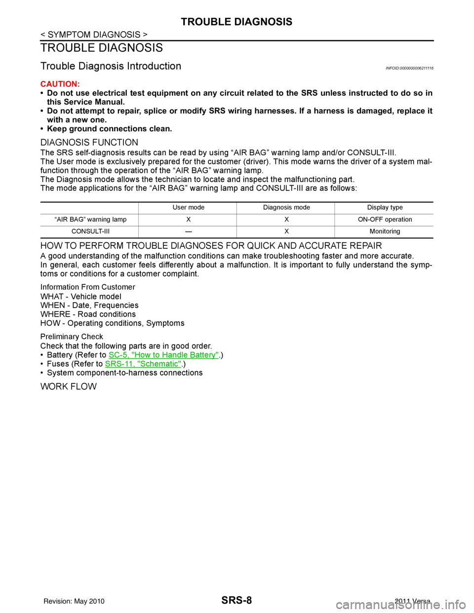
DIAGNOSIS FUNCTION
The SRS self-diagnosis results can be read by usi ng “AIR BAG” warning lamp and/or CONSULT-III.
The User mode is exclusively prepared for the customer (driver). This mode warns the driver of a system mal-
function through the operation of the “AIR BAG” warning lamp.
The Diagnosis mode allows the technician to locate and inspect the malfunctioning part.
The mode applications for the “AIR BAG” warning lamp and CONSULT-III are as follows:
HOW TO PERFORM TROUBLE DIAGNOSES FOR QUICK AND ACCURATE REPAIR
A good understanding of the malfunction conditions can make troubleshooting faster and more accurate.
In general, each customer feels differently about a malf unction. It is important to fully understand the symp-
toms or conditions for a customer complaint.
Information From Customer
WHAT - Vehicle model
WHEN - Date, Frequencies
WHERE - Road conditions
HOW - Operating conditions, Symptoms
Preliminary Check
Check that the following parts are in good order.
• Battery (Refer to SC-5, "
How to Handle Battery".)
• Fuses (Refer to SRS-11, "
Schematic".)
• System component-to-harness connections
WORK FLOW
User mode Diagnosis mode Display type
“AIR BAG” warning lamp XXON-OFF operation
CONSULT-III —XMonitoring
Revision: May 2010 2011 Versa