2011 NISSAN MURANO change time
[x] Cancel search: change timePage 3 of 433
Black plate (3,1)
Model "Z51-D" EDITED: 2010/ 7/ 23
All information, specifications and illustrations in
this manual are those in effect at the time of
printing. NISSAN reserves the right to change
specifications or design at any time without
notice.IMPORTANT INFORMATION ABOUT
THIS MANUALYou will see various symbols in this manual. They
are used in the following ways:
WARNING
This is used to indicate the presence of
a hazard that could cause death or
serious personal injury. To avoid or
reduce the risk, the procedures must
be followed precisely.
CAUTION
This is used to indicate the presence of
a hazard that could cause minor or
moderate personal injury or damage to
your vehicle. To avoid or reduce the risk,
the procedures must be followed care-
fully.
SIC0697
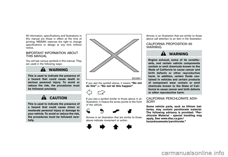
If you see the symbol above, it means“Do not
do this” or“Do not let this happen” .If you see a symbol similar to those above in an
illustration, it means the arrow points to the front
of the vehicle.Arrows in an illustration that are similar to those
above indicate movement or action.
Arrows in an illustration that are similar to those
above call attention to an item in the illustration.CALIFORNIA PROPOSITION 65
WARNING
WARNING
Engine exhaust, some of its constitu-
ents, and certain vehicle components
contain or emit chemicals known to the
State of California to cause cancer and
birth defects or other reproductive
harm. In addition, certain fluids con-
tained in vehicles and certain products
of component wear contain or emit
chemicals known to the State of Cali-
fornia to cause cancer and birth defects
or other reproductive harm.CALIFORNIA PERCHLORATE ADVI-
SORYSome vehicle parts, such as lithium bat-
teries, may contain perchlorate material.
The following advisory is provided: “Per-
chlorate Material - special handling may
apply, See www.dtsc.ca.gov/
hazardouswaste/perchlorate.”
Page 32 of 433
Black plate (30,1)
Model "Z51-D" EDITED: 2010/ 7/ 23
SSS0016SSS0014
WARNING
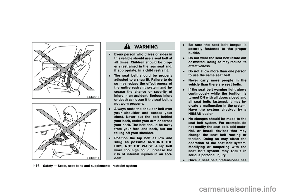
.Every person who drives or rides in
this vehicle should use a seat belt at
all times. Children should be prop-
erly restrained in the rear seat and,
if appropriate, in a child restraint.
. The seat belt should be properly
adjusted to a snug fit. Failure to do
so may reduce the effectiveness of
the entire restraint system and in-
crease the chance or severity of
injury in an accident. Serious injury
or death can occur if the seat belt is
not worn properly.
. Always route the shoulder belt over
your shoulder and across your
chest. Never put the belt behind
your back, under your arm or across
your neck. The belt should be away
from your face and neck, but not
falling off your shoulder.
. Position the lap belt as low and
snug as possible AROUND THE
HIPS, NOT THE WAIST. A lap belt
worn too high could increase the
risk of internal injuries in an acci-
dent. .
Be sure the seat belt tongue is
securely fastened to the proper
buckle.
. Do not wear the seat belt inside out
or twisted. Doing so may reduce its
effectiveness.
. Do not allow more than one person
to use the same seat belt.
. Never carry more people in the
vehicle than there are seat belts.
. If the seat belt warning light glows
continuously while the ignition is
turned ON with all doors closed and
all seat belts fastened, it may in-
dicate a malfunction in the system.
Have the system checked by a
NISSAN dealer.
. No changes should be made to the
seat belt system. For example, do
not modify the seat belt, add mate-
rial, or install devices that may
change the seat belt routing or
tension. Doing so may affect the
operation of the seat belt system.
Modifying or tampering with the
seat belt system may result in
serious personal injury.
. Once a seat belt pretensioner has
1-16
Safety — Seats, seat belts and supplemental restraint system
Page 83 of 433
Black plate (81,1)
Model "Z51-D" EDITED: 2010/ 7/ 23
ZONE VARIATION CHANGE PROCE-
DUREThe difference between magnetic north and
geographical north is known as variance. In
some areas, this difference can sometimes be
great enough to cause false compass readings.
Follow these instructions to set the variance for
your particular location if this happens:
1. Push the
switch for more than 3
seconds. The current zone number will
appear in the display.
2. Find your current location and variance number on the zone map.
NOTE:
Use zone number 5 for Hawaii.
3. Push theswitch repeatedly until the
new zone number appears in the display,
then release the switch. After you release
the switch, the display will show a compass
direction within a few seconds.
. If the compass deviates from the correct
indication soon after repeated adjust-
ment, have the compass checked at a
NISSAN dealer.
. The compass may not indicate the
correct compass point in tunnels or
while driving up or down a steep hill.
(The compass returns to the correct com- pass point when the vehicle moves to an
area where the geomagnetism is stabilized.)
CAUTION
.
Do not install a ski rack, antenna,
etc., which are attached to the
vehicle by means of a magnet. They
affect the operation of the compass.
. When cleaning the mirror, use a
paper towel or similar material
dampened with glass cleaner. Do
not spray glass cleaner directly on
the mirror as it may cause the liquid
cleaner to enter the mirror housing.
Instruments and controls
2-9
Page 95 of 433
Black plate (93,1)
Model "Z51-D" EDITED: 2010/ 7/ 23
INDICATORS FOR MAINTENANCE
1. Engine oil replacement indicatorThis indicator appears when the set time comes
for changing the engine oil. You can set or reset
the distance for changing the engine oil. (See
“TRIP COMPUTER” later in this section.)2. Oil filter replacement indicatorThis indicator appears when the set time comes
for replacing the oil filter. You can set or reset
the distance for replacing the oil filter. (See
“TRIP COMPUTER” later in this section.)3. Tire replacement indicatorThis indicator appears when the set time comes
for replacing tires. You can set or reset the
distance for replacing tires. (See “TRIP COM-
PUTER” later in this section.)4. “OTHER” indicatorThis indicator appears when the set time comes
for replacing items other than the engine oil, oil
filter and tires. You can set or reset the distance
for replacing the items. (See “TRIP COMPU-
TER” later in this section.)
More maintenance reminders are also available
on the center display. (See “HOW TO USE
INFO BUTTON” in the “4. Center display,
heater, air conditioner, audio, phone and voice
recognition systems” section.)
SIC3580
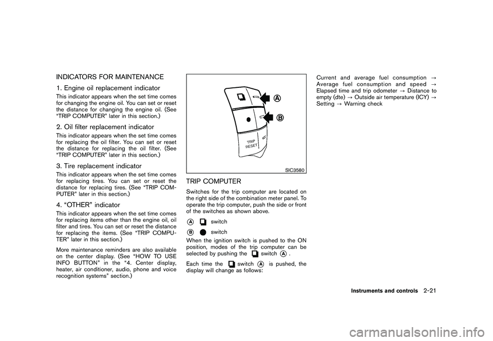
TRIP COMPUTERSwitches for the trip computer are located on
the right side of the combination meter panel. To
operate the trip computer, push the side or front
of the switches as shown above.*A
switch
*B
switch
When the ignition switch is pushed to the ON
position, modes of the trip computer can be
selected by pushing the
switch
*A
.
Each time the
switch
*A
is pushed, the
display will change as follows: Current and average fuel consumption
?
Average fuel consumption and speed ?
Elapsed time and trip odometer ?Distance to
empty (dte) ?Outside air temperature (ICY) ?
Setting ?Warning check
Instruments and controls
2-21
Page 97 of 433
Black plate (95,1)
Model "Z51-D" EDITED: 2010/ 7/ 23
SIC4701
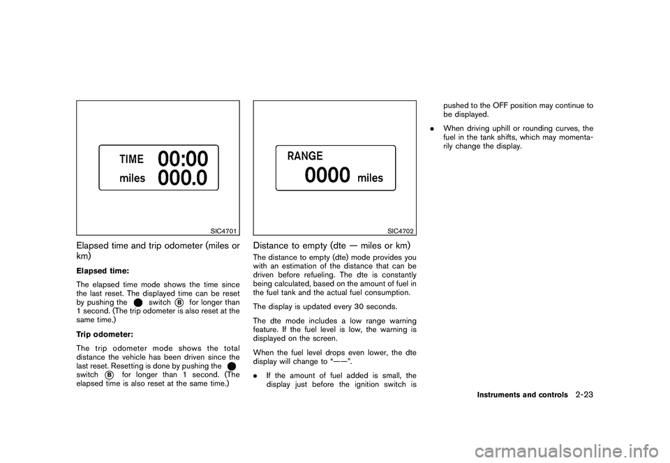
Elapsed time and trip odometer (miles or
km)Elapsed time:
The elapsed time mode shows the time since
the last reset. The displayed time can be reset
by pushing the
switch
*B
for longer than
1 second. (The trip odometer is also reset at the
same time.)
Trip odometer:
The trip odometer mode shows the total
distance the vehicle has been driven since the
last reset. Resetting is done by pushing the
switch
*B
for longer than 1 second. (The
elapsed time is also reset at the same time.)
SIC4702
Distance to empty (dte — miles or km)The distance to empty (dte) mode provides you
with an estimation of the distance that can be
driven before refueling. The dte is constantly
being calculated, based on the amount of fuel in
the fuel tank and the actual fuel consumption.
The display is updated every 30 seconds.
The dte mode includes a low range warning
feature. If the fuel level is low, the warning is
displayed on the screen.
When the fuel level drops even lower, the dte
display will change to “——”.
. If the amount of fuel added is small, the
display just before the ignition switch is pushed to the OFF position may continue to
be displayed.
. When driving uphill or rounding curves, the
fuel in the tank shifts, which may momenta-
rily change the display.
Instruments and controls
2-23
Page 101 of 433

Black plate (99,1)
Model "Z51-D" EDITED: 2010/ 7/ 23
.the key — master or mechanical
5. Confirm that the security indicator light
*A
comes on. The security indicator light stays
on for about 30 seconds. The vehicle
security system is now pre-armed. After
about 30 seconds the vehicle security
system automatically shifts into the armed
phase. The security light begins to flash
once every approximately 3 seconds. If,
during this 30-second pre-arm time period,
the door is unlocked, or the ignition switch is
pushed to ACC or ON, the system will not
arm.
Even when the driver and/or passengers
are in the vehicle, the system will activate
with all doors, hood and lift gate locked
withtheignitionswitchintheLOCK
position. When pushing the ignition switch
to the ACC or ON position, the system will
be released.
Vehicle security system activationThe vehicle security system will give the follow-
ing alarm:
. The headlights blink and the horn sounds
intermittently.
. The alarm automatica lly turns off after
approximately 1 minute. However, the alarm
reactivates if the vehicle is tampered with
again. The alarm is activated by:
.
Unlocking the door or opening the lift gate
without using the button on the Intelligent
Key, the request switch or the key. (Even if
the door is opened by releasing the door
inside lock knob, the alarm will activate.)
. Opening the hood.
How to stop an activated alarmThe alarm will stop by unlocking a door by
pushing the unlock button
on the Intelligent
Key, pushing the request switch or using the key.
The alarm will not stop if the ignition switch is
placed in the ACC or ON position.
If the system does not operate as de-
scribed above, have it checked by a
NISSAN dealer.
NISSAN VEHICLE IMMOBILIZER SYS-
TEMThe NISSAN Vehicle Immobilizer System will not
allow the engine to start without the use of the
registered key. Never leave these keys in the
vehicle.
Statement related to section 15 of FCC
rules for NISSAN Vehicle Immobilizer
System (CONT ASSY - CARD SLOT)
This device complies with part 15 of the
FCC Rules and RSS-210 of Industry Cana- da. Operation is subject to the following
two conditions;
(1) This device may not cause harmful
interference, and (2) this device must
accept any interference received, including
interference that may cause undesired
operation of the device.
CHANGES OR MODIFICATIONS NOT EX-
PRESSLY APPROVED BY THE PARTY
RESPONSIBLE FOR COMPLIANCE COULD
VOID THE USER’S AUTHORITY TO OPER-
ATE THE EQUIPMENT.
Instruments and controls
2-27
Page 134 of 433

Black plate (132,1)
Model "Z51-D" EDITED: 2010/ 7/ 23
NOTE:
If programming a garage door opener, etc.,
it is advised to unplug the device during
the “cycling” process to prevent possible
damage to the garage door opener com-
ponents.OPERATING THE HomeLink
®UNIVER-
SAL TRANSCEIVER
HomeLink
®Universal Transceiver (once pro-
grammed) may now be used to activate the
garage door, etc. To operate, simply push the
appropriate programmed HomeLink
®Universal
Transceiver button. The red indicator light will
illuminate while the signal is being transmitted.
PROGRAMMING TROUBLE-DIAGNO-
SISIf HomeLink
®does not quickly learn the hand-
held transmitter information:
. replace the hand-held transmitter batteries
with new batteries.
. position the hand-held transmitter with its
battery area facing away from the Home-
Link
®surface.
. push and hold both the HomeLink
®and
hand-held transmitter buttons without inter-
ruption.
. position the hand-held transmitter 2 to 5 in (50 to 127 mm) away from the HomeLink
®
surface. Hold the transmitter in that position
for up to 15 seconds. If HomeLink
®is not
programmed within that time, try holding the
transmitter in another position - keeping the
indicator light in view at all times.
If you continue to have programming difficulties,
please contact the NISSAN Consumer Affairs
Department. The phone numbers are located in
the Foreword of this Owner’s Manual.
CLEARING THE PROGRAMMED IN-
FORMATIONIndividual buttons cannot be cleared, however to
clear all programming, push and hold the two
outside buttons and release when the indicator
light begins to flash (in approximately 20
seconds) .REPROGRAMMING A SINGLE Home-
Link
®BUTTON
To reprogram a HomeLink
®Universal Transcei-
ver button, complete the following.
1. PushandholdthedesiredHomeLink
®
button. Do not release the button until step
4 has been completed.
2. When the indicator light begins to flash slowly (after 20 seconds), position the
hand-held transmitter 2 to 5 in (50 to 127
mm) away from the HomeLink
®surface. 3. Push and hold the hand-held transmitter
button.
4. The HomeLink
®indicator light will flash, first
slowly and then rapidly. When the indicator
light begins to flash rapidly, release both
buttons.
The HomeLink
®Universal Transceiver button has
now been reprogrammed. The new device can
be activated by pushing the HomeLink
®button
that was just programmed. This procedure will
not affect any other programmed HomeLink
®
buttons.IF YOUR VEHICLE IS STOLENIf your vehicle is stolen, you should change the
codes of any non-rolling code device that has
been programmed into HomeLink
®. Consult the
Owner’s Manual of each device or call the
manufacturer or dealer of those devices for
additional information.
When your vehicle is recovered, you will
need to reprogram the HomeLink
®Univer-
sal Transceiver with your new transmitter
information.
FCC Notice:
This device complies with FCC rules part
15. Operation is subject to the following
two conditions: (1) This device may not
cause harmful interference and (2) This
2-60
Instruments and controls
Page 191 of 433
Black plate (189,1)
Model "Z51-D" EDITED: 2010/ 7/ 23
.
(Stop)
Select the “
” key to stop the slideshow.
.
(Next)
Select the “
” key to display the next file.
.
(Previous)
Select the “
” key to display the previous
file.
Setting the Image Viewer:
The Image Viewer setting display will appear
when selecting the “Settings” key on the full
screen display. The following settings are
available for the full screen display.
. Slideshow Speed
Select the “Slideshow Speed” key. From the
following display, select the changing time
from 5, 10, 30, 60 seconds or “No Auto
Change”.
. Slideshow Order
Select the “Slideshow Order” key. From the
following display, select “Random” or “Order
List”. For “Order List”, the image order is the
order of the files as stored on the USB
memory. Operating tips:
.
Only files that meet the following conditions
will be displayed.
— Image type: JPEG
— File Extensions: *.jpg, *jpeg
— Maximum Resolution: 2048 61536
pixels
— Maximum Size: 2-MB
— Colors: 32768 (15-bit)
— Maximum File Name lengths: 253-Bytes
— Maximum Folders: 500
— Maximum Images per Folder: 1024
. If an electronic device (such as a digital
camera) is directly connected to the vehicle
using a USB cable, no image will be
displayed on the screen.
. If the file name is too long, some file names
may not be entirely displayed.
. When the total number of characters in the
file name exceeds 100 or if 1 file name in a
directory exceeds 100 characters, all files
will show a shortened 8-character version.
The image will still be displayed when
selected. When the selector lever is shifted into the R
(Reverse) position, the monitor display shows
the view to the rear of the vehicle.
The system is designed as an aid to the driver in
detecting large stationary objects to help avoid
damaging the vehicle. The system will not detect
small objects below the bumper and may not
detect objects close to the bumper or on the
ground.
WARNING
.
The rear view camera is a conve-
nience but it is not a substitute for
proper backing up. Always turn and
check that it is safe to do so before
backing up. Always back up slowly.
. Objects viewed in the RearView
Monitor differ from actual distance
because a wide-angle lens is used.
Objects in the RearView Monitor
will appear visually opposite than
when viewed in the rear view and
outside mirrors.
. Make sure that the lift gate is
securely closed when backing up.
. Underneath the bumper and the
corner areas of the bumper cannot
be viewed on the RearView MonitorREARVIEW MONITOR (if so
equipped)
Center display, heater, air conditioner, audio, phone and voice recognition systems
4-21