2011 NISSAN LATIO keyless
[x] Cancel search: keylessPage 687 of 3787
BACK DOOR LOCKBL-177
< SERVICE INFORMATION >
C
DE
F
G H
J
K L
M A
B
BL
N
O P
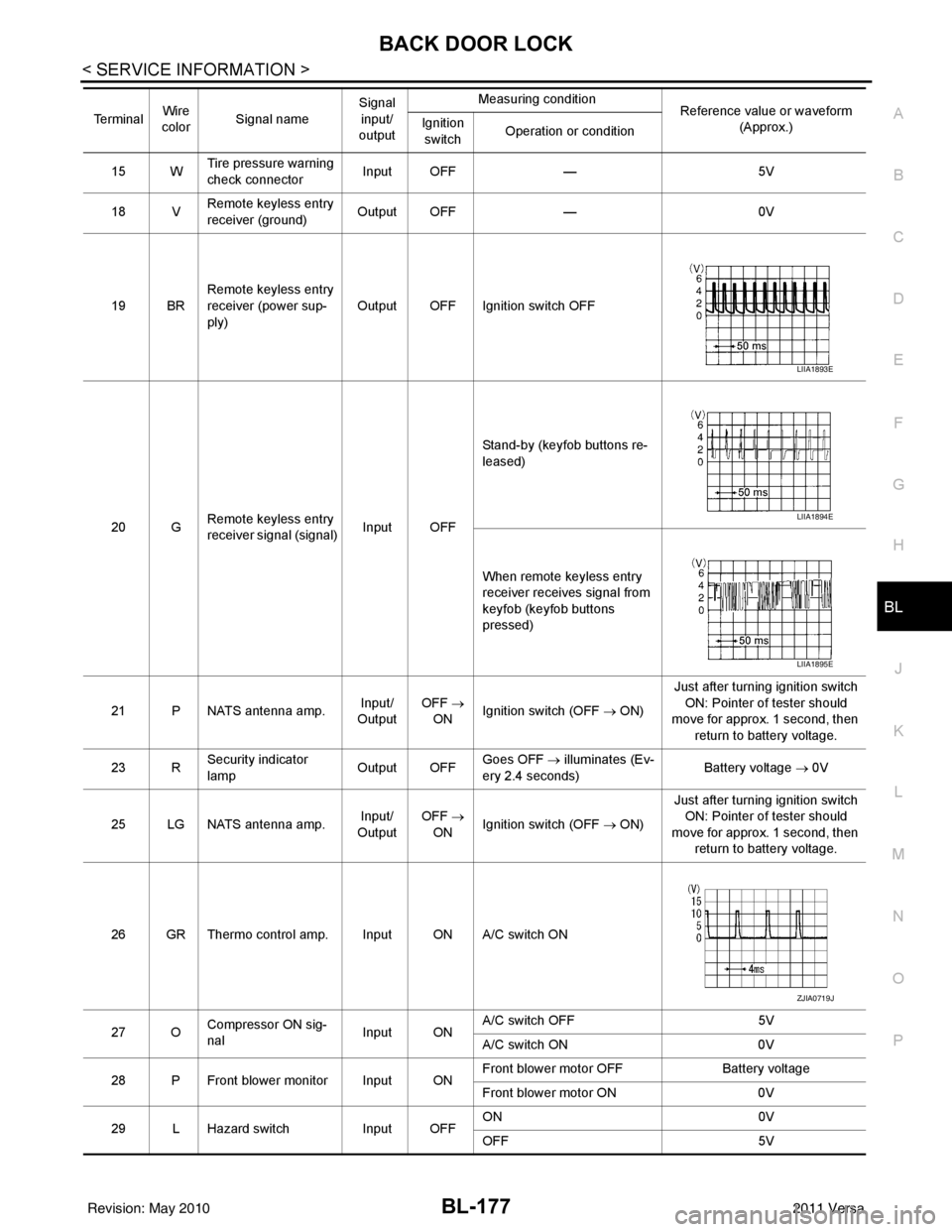
15 W Tire pressure warning
check connector
Input OFF
—5V
18 V Remote keyless entry
receiver (ground) Output OFF
—0V
19 BR Remote keyless entry
receiver (power sup-
ply) Output OFF Ignition switch OFF
20 G Remote keyless entry
receiver signal (signal)
Input OFFStand-by (keyfob buttons re-
leased)
When remote keyless entry
receiver receives signal from
keyfob (keyfob buttons
pressed)
21 P NATS antenna amp. Input/
Output OFF
→
ON Ignition switch (OFF → ON) Just after turning ignition switch
ON: Pointer of tester should
move for approx. 1 second, then
return to battery voltage.
23 R Security indicator
lamp Output OFF
Goes OFF
→ illuminates (Ev-
ery 2.4 seconds) Battery voltage
→ 0V
25 LG NATS antenna amp. Input/
Output OFF
→
ON Ignition switch (OFF → ON) Just after turning ignition switch
ON: Pointer of tester should
move for approx. 1 second, then return to battery voltage.
26 GR Thermo control amp. Input ON A/C switch ON
27 O Compressor ON sig-
nal Input ONA/C switch OFF
5V
A/C switch ON 0V
28 P Front blower monitor Input ON Front blower motor OFF
Battery voltage
Front blower motor ON 0V
29 L Hazard switch Input OFFON
0V
OFF 5V
Te r m i n a l
Wire
color Signal name Signal
input/
output Measuring condition
Reference value or waveform
(Approx.)
Ignition
switch Operation or condition
LIIA1893E
LIIA1894E
LIIA1895E
ZJIA0719J
Revision: May 2010
2011 Versa
Page 712 of 3787
BL-202
< SERVICE INFORMATION >
TRUNK LID OPENER
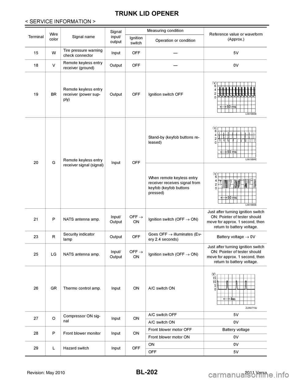
15 WTire pressure warning
check connector
Input OFF
—5V
18 V Remote keyless entry
receiver (ground) Output OFF
—0V
19 BR Remote keyless entry
receiver (power sup-
ply) Output OFF Ignition switch OFF
20 G Remote keyless entry
receiver signal (signal)
Input OFFStand-by (keyfob buttons re-
leased)
When remote keyless entry
receiver receives signal from
keyfob (keyfob buttons
pressed)
21 P NATS antenna amp. Input/
Output OFF
→
ON Ignition switch (OFF
→ ON)Just after turning ignition switch
ON: Pointer of tester should
move for approx. 1 second, then
return to battery voltage.
23 R Security indicator
lamp Output OFF
Goes OFF
→ illuminates (Ev-
ery 2.4 seconds) Battery voltage
→ 0V
25 LG NATS antenna amp. Input/
Output OFF
→
ON Ignition switch (OFF
→ ON)Just after turning ignition switch
ON: Pointer of tester should
move for approx. 1 second, then return to battery voltage.
26 GR Thermo control amp. Input ON A/C switch ON
27 O Compressor ON sig-
nal Input ONA/C switch OFF
5V
A/C switch ON 0V
28 P Front blower monitor Input ON Front blower motor OFF
Battery voltage
Front blower motor ON 0V
29 L Hazard switch Input OFFON
0V
OFF 5V
Te r m i n a l
Wire
color Signal name Signal
input/
output Measuring condition
Reference value or waveform
(Approx.)
Ignition
switch Operation or condition
LIIA1893E
LIIA1894E
LIIA1895E
ZJIA0719J
Revision: May 2010
2011 Versa
Page 729 of 3787

VEHICLE SECURITY (THEFT WARNING) SYSTEMBL-219
< SERVICE INFORMATION >
C
DE
F
G H
J
K L
M A
B
BL
N
O P
• to combination meter terminal 27 (security indicator lamp)
• through 40A fusible link (letter g, located in the fuse and fusible link box)
• to BCM terminal 70
• through 10A fuse [No. 8, located in the fuse block (J/B)]
• to BCM terminal 57
• through 10A fuse (No. 28, located in the fuse and fusible link box)
• to horn relay terminal 2
• through 15A fuse (No. 52, located in the IPDM E/R)
• to IPDM E/R internal CPU.
• through 20A fuse (No. 53, located in the IPDM E/R)
• to IPDM E/R internal CPU.
With the ignition switch in the ACC or ON position, power is supplied• through 10A fuse [No. 20, located in the fuse block (J/B)]
• to BCM terminal 11.
With the ignition switch in the ON or START position, power is supplied• through 10A fuse [No. 6, located in the fuse block (J/B)]
• to BCM terminal 38.
Ground is supplied• to BCM terminal 67
• through body grounds M57 and M61.
INITIAL CONDITION TO ACTIVATE THE SYSTEM
The operation of the vehicle security system is controlled by the doors and trunk (sedan).
To activate the vehicle security system, BCM must receive signals indicating the ignition switch is OFF, doors
and trunk (sedan) are closed and locked.
When a door or trunk (sedan) is open, BCM terminal 12, 13, 42, 43, 47 or 48 receives a ground signal from
each door or trunk switch. In addition to BCM, when back door is open, the Intelligent Key unit terminal 23
receives a ground signal from back door or trunk (sedan) through BCM terminal 30.
When front door LH is unlocked, BCM terminal 46 receives a signal from terminal 6 of main power window and
door lock/unlock switch.
When front door RH is unlocked, BCM terminal 46 receives a signal from terminal 2 of power window and door
lock/unlock switch RH.
VEHICLE SECURITY SYSTEM ALARM OPERATION
The vehicle security system is triggered by
• Opening a door without using the key, keyfob or Intelligent Key.
• Opening trunk without using the key, keyfob or Intelligent Key (sedan).
The vehicle security system will be triggered once the system is in armed phase,
• when BCM receives a ground signal at terminals 12, 13, 47, 48 (front or rear door switch), terminal 42 (sedan, trunk switch) or terminal 43 (hatchback, back door switch).
When the vehicle security system is triggered, ground is supplied intermittently
• from IPDM E/R terminal 45
• to horn relay terminal 1.
The headlamps flash and the hor n sounds intermittently.
The alarm automatically turns off after 50 seconds, but will reactivate if the vehicle is tampered with again.
VEHICLE SECURITY SYSTEM DEACTIVATION
To deactivate the vehicle security system, a door or trunk (sedan) must be unlocked with the key, keyfob or
Intelligent Key.
When the key is used to unlock the driver door, BCM terminal 7 receives signal
• from terminal 3 of the front door lock assembly LH (key cylinder switch).
When the key is used to open the trunk (sedan), BCM terminal 41 receives signal
• from terminal 1 of the trunk key cylinder switch.
When the BCM receives an unlock signal from keyfob, Intelligent Key, front door key cylinder switch LH or
trunk key cylinder switch (sedan), the vehicle security system is deactivated (Disarmed phase).
PANIC ALARM OPERATION
Intelligent Key and remote keyless entry system may or may not operate vehicle security system (horn and
headlamps) as required.
When the vehicle security system is triggered, ground is supplied intermittently
Revision: May 2010 2011 Versa
Page 737 of 3787
VEHICLE SECURITY (THEFT WARNING) SYSTEMBL-227
< SERVICE INFORMATION >
C
DE
F
G H
J
K L
M A
B
BL
N
O P
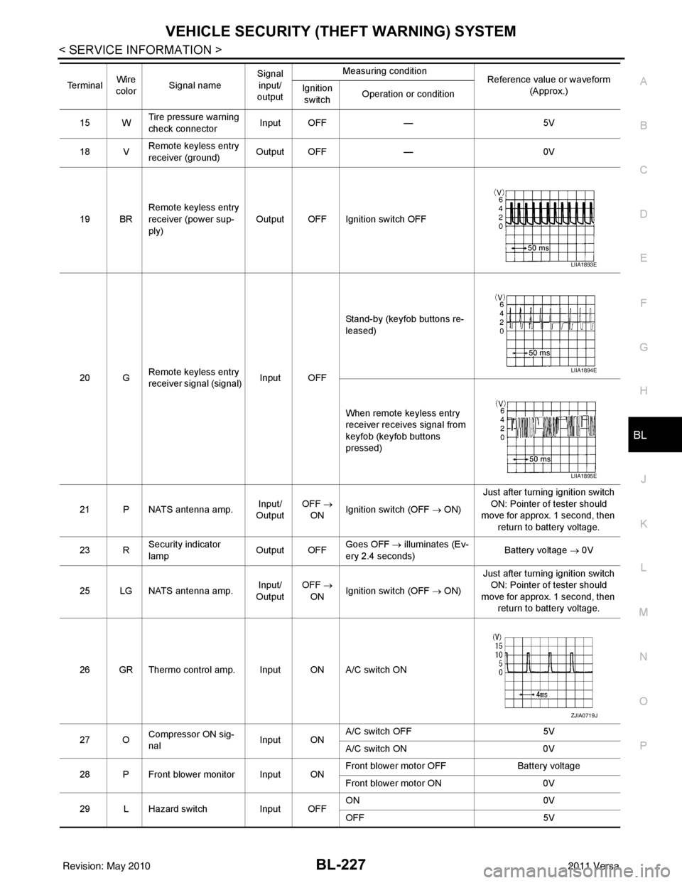
15 W Tire pressure warning
check connector
Input OFF
—5V
18 V Remote keyless entry
receiver (ground) Output OFF
—0V
19 BR Remote keyless entry
receiver (power sup-
ply) Output OFF Ignition switch OFF
20 G Remote keyless entry
receiver signal (signal)
Input OFFStand-by (keyfob buttons re-
leased)
When remote keyless entry
receiver receives signal from
keyfob (keyfob buttons
pressed)
21 P NATS antenna amp. Input/
Output OFF
→
ON Ignition switch (OFF → ON) Just after turning ignition switch
ON: Pointer of tester should
move for approx. 1 second, then
return to battery voltage.
23 R Security indicator
lamp Output OFF
Goes OFF
→ illuminates (Ev-
ery 2.4 seconds) Battery voltage
→ 0V
25 LG NATS antenna amp. Input/
Output OFF
→
ON Ignition switch (OFF → ON) Just after turning ignition switch
ON: Pointer of tester should
move for approx. 1 second, then return to battery voltage.
26 GR Thermo control amp. Input ON A/C switch ON
27 O Compressor ON sig-
nal Input ONA/C switch OFF
5V
A/C switch ON 0V
28 P Front blower monitor Input ON Front blower motor OFF
Battery voltage
Front blower motor ON 0V
29 L Hazard switch Input OFFON
0V
OFF 5V
Te r m i n a l
Wire
color Signal name Signal
input/
output Measuring condition
Reference value or waveform
(Approx.)
Ignition
switch Operation or condition
LIIA1893E
LIIA1894E
LIIA1895E
ZJIA0719J
Revision: May 2010
2011 Versa
Page 743 of 3787

VEHICLE SECURITY (THEFT WARNING) SYSTEMBL-233
< SERVICE INFORMATION >
C
DE
F
G H
J
K L
M A
B
BL
N
O P
CONSULT-III APPLICATION ITEM
Work Support
Data Monitor
* : With remote keyless entry system
** : With Intelligent Key system
Active Test
Test Item Description
SECURITY ALARM SET This mode can confirm and change security alarm ON-OFF setting.
THEFT ALM TRG The switch which triggered vehicle security alarm is recorded. This mode is able to confirm and
erase the record of vehicle security alarm. The trigger data can be erased by touching “CLEAR” on
CONSULT-III screen.
Monitored Item
Description
IGN ON SW Indicates [ON/OFF] condition of ignition switch.
ACC ON SW Indicates [ON/OFF] condition of ignition switch in ACC position.
KEYLESS LOCK* Indicates [ON/OFF] condition of lock signal from keyfob.
KEYLESS UNLOCK* Indicates [ON/OFF] condition of unlock signal from keyfob.
I-KEY LOCK** Indicates [ON/OFF] condition of lock signal from keyfob.
I-KEY UNLOCK** Indicates [ON/OFF] condition of unlock signal from keyfob.
TRNK OPNR SW Indicates [ON/OFF] condition of trunk opener switch.
TRUNK CYL SW Indicates [ON/OFF] condition of trunk key cylinder switch.
TRNK OPN MNTR Indicates [ON/OFF] condition of trunk lid status.
DOOR SW-DR Indicates [ON/OFF] condition of front door switch LH.
DOOR SW-AS Indicates [ON/OFF] condition of front door switch RH.
DOOR SW-RR Indicates [ON/OFF] condition of rear door switch RH.
DOOR SW-RL Indicates [ON/OFF] condition of rear door switch LH.
BACK DOOR SW Indicates [ON/OFF] condition of back door switch.
KEY CYL LK-SW Indicates [ON/OFF] condition of lock signal from key cylinder switch.
KEY CYL UN-SW Indicates [ON/OFF] condition of unlock signal from key cylinder switch.
CDL LOCK SW Indicates [ON/OFF] condition of lock signal from door lock/unlock switch LH and RH.
CDL UNLOCK SW Indicates [ON/OFF] condition of unlock signal from door lock/unlock switch LH and RH.
Test Item Description
THEFT IND This test is able to check security indicator lamp operation. The lamp will be turned on when “ON”
on CONSULT-III screen is touched.
VEHICLE SECURITY HORN This test is able to check vehicle security horn operation. The horns will be activated for 0.5 sec-
onds after “ON” on CONSULT-III screen is touched.
HEADLAMP (HI) This test is able to check vehicle security lamp operation. The headlamps will be activated for 0.5
seconds after “ON” on CONSULT-III screen is touched.
Revision: May 2010
2011 Versa
Page 744 of 3787
BL-234
< SERVICE INFORMATION >
VEHICLE SECURITY (THEFT WARNING) SYSTEM
Trouble Diagnosis
INFOID:0000000005929419
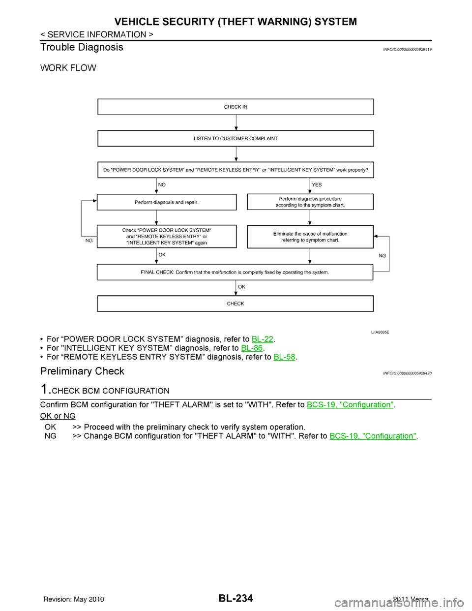
WORK FLOW
• For “POWER DOOR LOCK SYSTEM” diagnosis, refer to BL-22.
• For "INTELLIGENT KEY SYSTEM” diagnosis, refer to BL-86
.
• For “REMOTE KEYLESS ENTRY SYSTEM” diagnosis, refer to BL-58
.
Preliminary CheckINFOID:0000000005929420
1.CHECK BCM CONFIGURATION
Confirm BCM configuration for "THEFT ALARM" is set to "WITH". Refer to BCS-19, "
Configuration".
OK or NG
OK >> Proceed with the preliminary check to verify system operation.
NG >> Change BCM configuration for "THEFT ALARM" to "WITH". Refer to BCS-19, "
Configuration".
LIIA2635E
Revision: May 2010 2011 Versa
Page 746 of 3787
BL-236
< SERVICE INFORMATION >
VEHICLE SECURITY (THEFT WARNING) SYSTEM
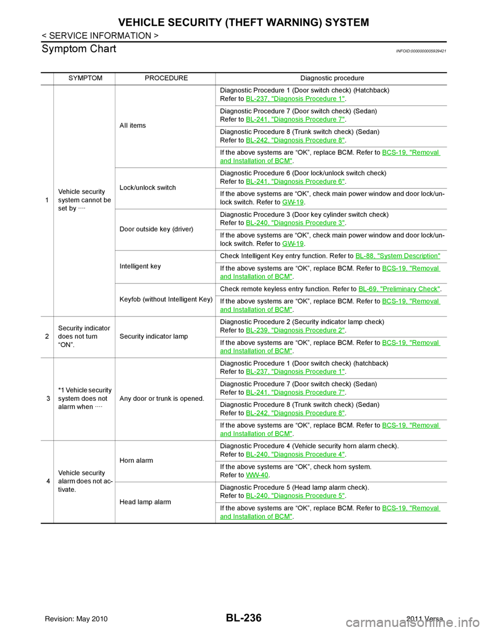
Symptom Chart
INFOID:0000000005929421
SYMPTOM PROCEDURE Diagnostic procedure
1 Vehicle security
system cannot be
set by ···· AII items
Diagnostic Procedure 1 (Door switch check) (Hatchback)
Refer to
BL-237, "
Diagnosis Procedure 1".
Diagnostic Procedure 7 (Door switch check) (Sedan)
Refer to BL-241, "
Diagnosis Procedure 7".
Diagnostic Procedure 8 (Trunk switch check) (Sedan)
Refer to BL-242, "
Diagnosis Procedure 8".
If the above systems are “OK”, replace BCM. Refer to BCS-19, "
Removal
and Installation of BCM".
Lock/unlock switch Diagnostic Procedure 6 (Door lock/unlock switch check)
Refer to
BL-241, "
Diagnosis Procedure 6".
If the above systems are “OK”, check main power window and door lock/un-
lock switch. Refer to GW-19
.
Door outside key (driver) Diagnostic Procedure 3 (Door key cylinder switch check)
Refer to
BL-240, "
Diagnosis Procedure 3".
If the above systems are “OK”, check main power window and door lock/un-
lock switch. Refer to GW-19
.
Intelligent key Check Intelligent Key entry function. Refer to
BL-88, "
System Description"
If the above systems are “OK”, replace BCM. Refer to BCS-19, "Removal
and Installation of BCM".
Keyfob (without Intelligent Key) Check remote keyless entry function. Refer to
BL-69, "
Preliminary Check".
If the above systems are “OK”, replace BCM. Refer to BCS-19, "
Removal
and Installation of BCM".
2 Security indicator
does not turn
“ON”.
Security indicator lamp Diagnostic Procedure 2 (Security indicator lamp check)
Refer to
BL-239, "
Diagnosis Procedure 2".
If the above systems are “OK”, replace BCM. Refer to BCS-19, "
Removal
and Installation of BCM".
3 *1 Vehicle security
system does not
alarm when ····
Any door or trunk is opened. Diagnostic Procedure 1 (Door switch check) (hatchback)
Refer to
BL-237, "
Diagnosis Procedure 1".
Diagnostic Procedure 7 (Door switch check) (Sedan)
Refer to BL-241, "
Diagnosis Procedure 7".
Diagnostic Procedure 8 (Trunk switch check) (Sedan)
Refer to BL-242, "
Diagnosis Procedure 8".
If the above systems are “OK”, replace BCM. Refer to BCS-19, "
Removal
and Installation of BCM".
4 Vehicle security
alarm does not ac-
tivate. Horn alarm
Diagnostic Procedure 4 (Vehicle security horn alarm check).
Refer to
BL-240, "
Diagnosis Procedure 4".
If the above systems are “OK”, check horn system.
Refer to WW-40
.
Head lamp alarm Diagnostic Procedure 5 (Head lamp alarm check).
Refer to
BL-240, "
Diagnosis Procedure 5".
If the above systems are “OK”, replace BCM. Refer to BCS-19, "
Removal
and Installation of BCM".
Revision: May 2010 2011 Versa
Page 747 of 3787
VEHICLE SECURITY (THEFT WARNING) SYSTEMBL-237
< SERVICE INFORMATION >
C
DE
F
G H
J
K L
M A
B
BL
N
O P
*1 : Make sure the system is in the armed phase.
Diagnosis Procedure 1INFOID:0000000005929422
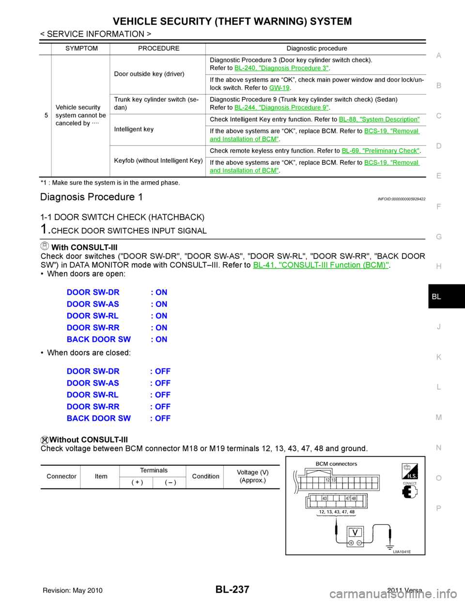
1-1 DOOR SWITCH CHECK (HATCHBACK)
1.CHECK DOOR SWITCHES INPUT SIGNALWith CONSULT-III
Check door switches ("DOOR SW-DR", "DOOR SW-AS", "DOOR SW-RL", "DOOR SW-RR", "BACK DOOR
SW") in DATA MONITOR mode with CONSULT–III. Refer to BL-41, "
CONSULT-III Function (BCM)".
• When doors are open:
• When doors are closed:
Without CONSULT-III
Check voltage between BCM connector M18 or M19 terminals 12, 13, 43, 47, 48 and ground.
5 Vehicle security
system cannot be
canceled by ···· Door outside key (driver)
Diagnostic Procedure 3 (Door key cylinder switch check).
Refer to BL-240, "
Diagnosis Procedure 3".
If the above systems are “OK”, check main power window and door lock/un-
lock switch. Refer to GW-19
.
Trunk key cylinder switch (se-
dan) Diagnostic Procedure 9 (Trunk key cylinder switch check) (Sedan)
Refer to BL-244, "
Diagnosis Procedure 9".
Intelligent key Check Intelligent Key entry function. Refer to
BL-88, "
System Description"
If the above systems are “OK”, replace BCM. Refer to BCS-19, "Removal
and Installation of BCM".
Keyfob (without Intelligent Key) Check remote keyless entry function. Refer to
BL-69, "
Preliminary Check".
If the above systems are “OK”, replace BCM. Refer to BCS-19, "
Removal
and Installation of BCM".
SYMPTOM
PROCEDURE Diagnostic procedure
DOOR SW-DR : ON
DOOR SW-AS : ON
DOOR SW-RL : ON
DOOR SW-RR : ON
BACK DOOR SW : ON
DOOR SW-DR : OFF
DOOR SW-AS : OFF
DOOR SW-RL : OFF
DOOR SW-RR : OFF
BACK DOOR SW : OFF
Connector ItemTe r m i n a l s
ConditionVoltage (V)
(Approx.)
( + ) ( – )
LIIA1041E
Revision: May 2010 2011 Versa