2011 NISSAN LATIO brake
[x] Cancel search: brakePage 98 of 3787
TROUBLE DIAGNOSISAT-81
< SERVICE INFORMATION >
DE
F
G H
I
J
K L
M A
B
AT
N
O P
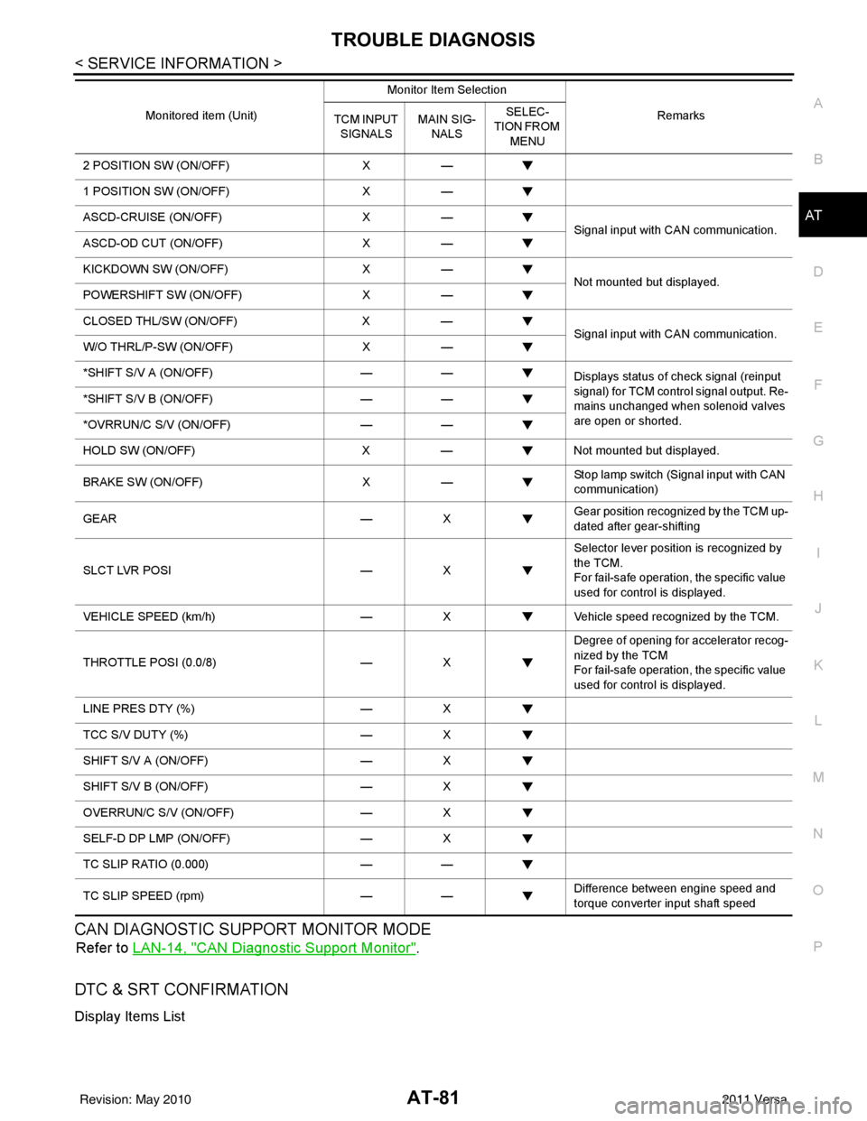
CAN DIAGNOSTIC SUPPORT MONITOR MODE
Refer to LAN-14, "CAN Diagnostic Support Monitor".
DTC & SRT CONFIRMATION
Display Items List
2 POSITION SW (ON/OFF) X—
1 POSITION SW (ON/OFF) X—
ASCD-CRUISE (ON/OFF) X—
Signal input with CAN communication.
ASCD-OD CUT (ON/OFF) X—
KICKDOWN SW (ON/OFF) X—
Not mounted but displayed.
POWERSHIFT SW (ON/OFF) X—
CLOSED THL/SW (ON/OFF) X—
Signal input with CAN communication.
W/O THRL/P-SW (ON/OFF) X—
*SHIFT S/V A (ON/OFF) ——
Displays status of check signal (reinput
signal) for TCM control signal output. Re-
mains unchanged when solenoid valves
are open or shorted.
*SHIFT S/V B (ON/OFF)
——
*OVRRUN/C S/V (ON/OFF) ——
HOLD SW (ON/OFF) X— Not mounted but displayed.
BRAKE SW (ON/OFF) X— Stop lamp switch (Signal input with CAN
communication)
GEAR —X Gear position recognized by the TCM up-
dated after gear-shifting
SLCT LVR POSI —X Selector lever position is recognized by
the TCM.
For fail-safe operation, the specific value
used for control is displayed.
VEHICLE SPEED (km/h) —X Vehicle speed reco gnized by the TCM.
THROTTLE POSI (0.0/8) —X Degree of opening for accelerator recog-
nized by the TCM
For fail-safe operation, the specific value
used for control is displayed.
LINE PRES DTY (%) —X
TCC S/V DUTY (%) —X
SHIFT S/V A (ON/OFF) —X
SHIFT S/V B (ON/OFF) —X
OVERRUN/C S/V (ON/OFF) —X
SELF-D DP LMP (ON/OFF) —X
TC SLIP RATIO (0.000) ——
TC SLIP SPEED (rpm) —— Difference between engine speed and
torque converter input shaft speed
Monitored item (Unit)
Monitor Item Selection
Remarks
TCM INPUT
SIGNALS MAIN SIG-
NALS SELEC-
TION FROM
MENU
Revision: May 2010 2011 Versa
Page 132 of 3787

P0733 3GR INCORRECT RATIOAT-115
< SERVICE INFORMATION >
DE
F
G H
I
J
K L
M A
B
AT
N
O P
P0733 3GR INCORRECT RATIO
DescriptionINFOID:0000000005928153
• This malfunction will not be detected while the OD OFF indicator lamp is indicating another self-diagnosis malfunction.
• This malfunction is detected when the A/T does not shif t into third gear position as instructed by the TCM.
This is not caused by electrical malfunction (circuit s open or shorted) but by mechanical malfunction such as
control valve sticking, improper solenoid valve operat ion, malfunctioning servo piston or brake band, etc.
On Board Diagnosis LogicINFOID:0000000005928154
• This is an OBD-II self-diagnostic item.
• Diagnostic trouble code “P0733 3GR INCORRECT RATIO” with CONSULT-III is detected when A/T cannot
be shifted to the 3GR position even if electrical circuit is good.
• This diagnosis monitors actual gear position by checki ng the torque converter slip ratio calculated by TCM
as follows:
Torque converter slip ratio = A x C/B
A: Output shaft revolution signal from output speed sensor
B: Engine speed signal from ECM
C: Gear ratio determined as gear position which TCM supposes
If the actual gear position is higher than the position (3rd) supposed by TCM, the slip ratio will be more than
normal. In case the ratio exceeds the specif ied value, TCM judges this diagnosis malfunction.
This malfunction will be caused when shift solenoid valve A is stuck closed.
• Gear positions supposed by TCM are as follows. In case of gear position with no malfunctions: 1, 2, 3 and 4 positions
In case of gear position with shift solenoid valve A stuck closed: 1, 1, 4* and 4 positions to each gear position
above
*: “P0733 3GR INCORRECT RATIO” is detected.
Possible CauseINFOID:0000000005928155
• Shift solenoid valve A
• Each clutch
• Hydraulic control circuit
DTC Confirmation ProcedureINFOID:0000000005928156
CAUTION:
• Always drive vehicle at a safe speed.
• If performing this “DTC Confirmation Procedure” again, always turn ignition switch OFF and wait at
least 10 seconds before continuing.
After the repair, perform the following procedure to confirm the malfunction is eliminated.
WITH CONSULT-III
1. Start engine and select “DATA MONITOR” m ode for “TRANSMISSION” with CONSULT-III.
2. Touch “START”.
3. Make sure that output voltage of A/T fluid temperature sensor is within the range below. FLUID TEMP SE: 0.4 - 1.5 V
If out of range, drive the vehicle to decrease the vo ltage (warm up the fluid) or stop engine to increase the
voltage (cool down the fluid).
4. Select “3RD GR FNCTN P0733” of “DTC & SR T CONFIRMATION” mode for “TRANSMISSION” with
CONSULT-III and touch “START”.
5. Accelerate vehicle to 60 to 75 km/h (37 to 47 MPH) under the following conditions and release the accel- erator pedal completely.
THROTTLE POSI: Less th an 1.0/8 (at all times during step 4)
SLCT LVR POSI: “D” position
Gear position 123 4
Shift solenoid valve A ON (Closed)OFF (Open)OFF (Open)ON (Closed)
Shift solenoid valve B ON (Closed)ON (Closed) OFF (Open)OFF (Open)
Revision: May 2010 2011 Versa
Page 150 of 3787
P0745 PRESSURE CONTROL SOLENOID AAT-133
< SERVICE INFORMATION >
DE
F
G H
I
J
K L
M A
B
AT
N
O P
P0745 PRESSURE CONTROL SOLENOID A
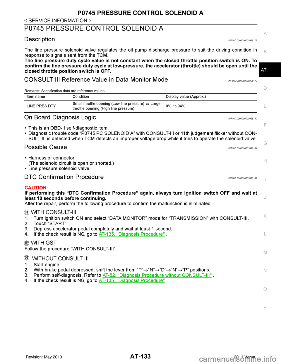
DescriptionINFOID:0000000005928178
The line pressure solenoid valve regulates the oil pum p discharge pressure to suit the driving condition in
response to signals sent from the TCM.
The line pressure duty cycle value is not constant when the closed throttle po sition switch is ON. To
confirm the line pressure duty cycle at low-pressure, the accelerator (throttle) sh ould be open until the
closed throttle position switch is OFF.
CONSULT-III Reference Val ue in Data Monitor ModeINFOID:0000000005928179
Remarks: Specification data are reference values.
On Board Diagnosis LogicINFOID:0000000005928180
• This is an OBD-II self-diagnostic item.
• Diagnostic trouble code “P0745 PC SOLENOID A” with CO NSULT-III or 11th judgement flicker without CON-
SULT-III is detected when TCM detects an improper volt age drop while it tries to operate the solenoid valve.
Possible CauseINFOID:0000000005928181
• Harness or connector
(The solenoid circuit is open or shorted.)
• Line pressure solenoid valve
DTC Confirmation ProcedureINFOID:0000000005928182
CAUTION:
If performing this “DTC Confirmati on Procedure” again, always turn ignition switch OFF and wait at
least 10 seconds before continuing.
After the repair, perform the following procedure to confirm the malfunction is eliminated.
WITH CONSULT-III
1. Turn ignition switch ON and select “DATA MO NITOR” mode for “TRANSMISSION” with CONSULT-III.
2. Touch “START”.
3. Depress accelerator pedal completely and wait at least 1 second.
4. If the check result is NG, go to AT-135, "
Diagnosis Procedure" .
WITH GST
Follow the procedure “WITH CONSULT-III”.
WITHOUT CONSULT-III
1. Start engine.
2. With brake pedal depressed, shift the lever from “P” →“N” →“D” →“N” →“P” positions.
3. Perform self-diagnosis. Refer to AT-82, "
Diagnosis Procedure without CONSULT-III" .
4. If the check result is NG, go to AT-135, "
Diagnosis Procedure" .
Item nameCondition Display value (Approx.)
LINE PRES DTY Small throttle opening (Low line pressure)
⇔ Large
throttle opening (High line pressure) 0%
⇔ 94%
Revision: May 2010 2011 Versa
Page 203 of 3787
AT-186
< SERVICE INFORMATION >
TROUBLE DIAGNOSIS FOR SYMPTOMS
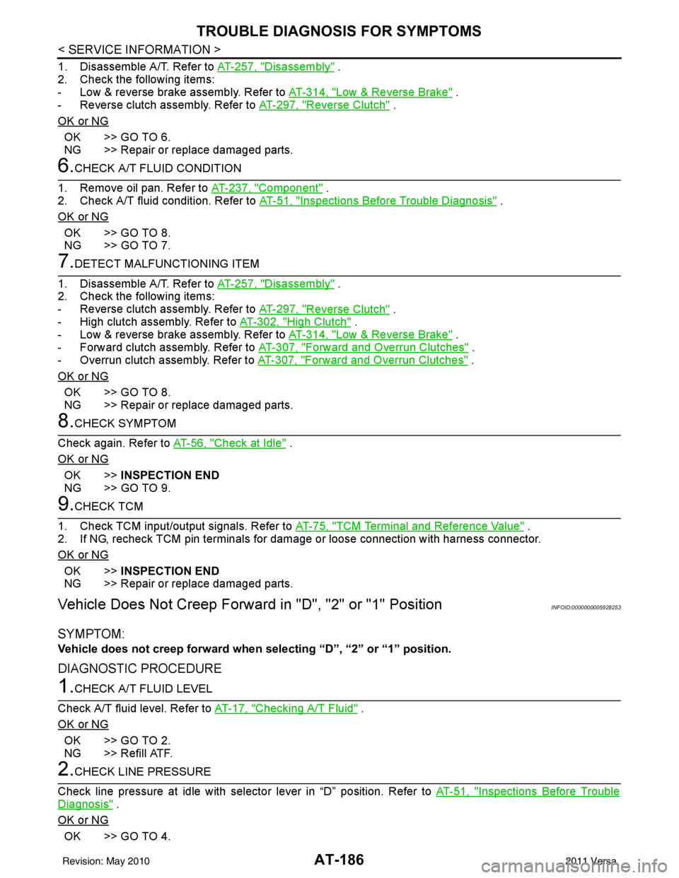
1. Disassemble A/T. Refer to AT-257, "Disassembly" .
2. Check the following items:
- Low & reverse brake assembly. Refer to AT-314, "
Low & Reverse Brake" .
- Reverse clutch assembly. Refer to AT-297, "
Reverse Clutch" .
OK or NG
OK >> GO TO 6.
NG >> Repair or replace damaged parts.
6.CHECK A/T FLUID CONDITION
1. Remove oil pan. Refer to AT-237, "
Component" .
2. Check A/T fluid condition. Refer to AT-51, "
Inspections Before Trouble Diagnosis" .
OK or NG
OK >> GO TO 8.
NG >> GO TO 7.
7.DETECT MALFUNCTIONING ITEM
1. Disassemble A/T. Refer to AT-257, "
Disassembly" .
2. Check the following items:
- Reverse clutch assembly. Refer to AT-297, "
Reverse Clutch" .
- High clutch assembly. Refer to AT-302, "
High Clutch" .
- Low & reverse brake assembly. Refer to AT-314, "
Low & Reverse Brake" .
- Forward clutch assembly. Refer to AT-307, "
Forward and Overrun Clutches" .
- Overrun clutch assembly. Refer to AT-307, "
Forward and Overrun Clutches" .
OK or NG
OK >> GO TO 8.
NG >> Repair or replace damaged parts.
8.CHECK SYMPTOM
Check again. Refer to AT-56, "
Check at Idle" .
OK or NG
OK >> INSPECTION END
NG >> GO TO 9.
9.CHECK TCM
1. Check TCM input/output signals. Refer to AT-75, "
TCM Terminal and Reference Value" .
2. If NG, recheck TCM pin terminals for damage or loose connection with harness connector.
OK or NG
OK >> INSPECTION END
NG >> Repair or replace damaged parts.
Vehicle Does Not Creep Forward in "D", "2" or "1" PositionINFOID:0000000005928253
SYMPTOM:
Vehicle does not creep forward when selecting “D”, “2” or “1” position.
DIAGNOSTIC PROCEDURE
1.CHECK A/T FLUID LEVEL
Check A/T fluid level. Refer to AT-17, "
Checking A/T Fluid" .
OK or NG
OK >> GO TO 2.
NG >> Refill ATF.
2.CHECK LINE PRESSURE
Check line pressure at idle with selector lever in “D” position. Refer to AT-51, "
Inspections Before Trouble
Diagnosis" .
OK or NG
OK >> GO TO 4.
Revision: May 2010 2011 Versa
Page 207 of 3787
AT-190
< SERVICE INFORMATION >
TROUBLE DIAGNOSIS FOR SYMPTOMS
OK or NG
OK >> GO TO 5.
NG >> Repair or replace accelerator pedal position sensor.
5.CHECK A/T FLUID CONDITION
1. Remove oil pan. Refer to AT-237, "
Component" .
2. Check A/T fluid condition. Refer to AT-51, "
Inspections Before Trouble Diagnosis" .
OK or NG
OK >> GO TO 7.
NG >> GO TO 6.
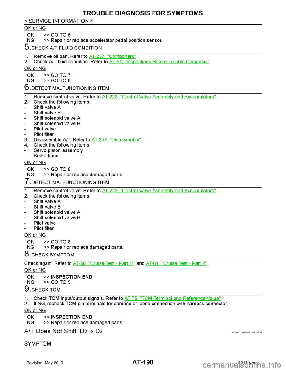
6.DETECT MALFUNCTIONING ITEM
1. Remove control valve. Refer to AT-222, "
Control Valve Assembly and Accumulators" .
2. Check the following items:
- Shift valve A
- Shift valve B
- Shift solenoid valve A
- Shift solenoid valve B
- Pilot valve
- Pilot filter
3. Disassemble A/T. Refer to AT-257, "
Disassembly" .
4. Check the following items:
- Servo piston assembly
- Brake band
OK or NG
OK >> GO TO 8.
NG >> Repair or replace damaged parts.
7.DETECT MALFUNCTIONING ITEM
1. Remove control valve. Refer to AT-222, "
Control Valve Assembly and Accumulators" .
2. Check the following items:
- Shift valve A
- Shift valve B
- Shift solenoid valve A
- Shift solenoid valve B
- Pilot valve
- Pilot filter
OK or NG
OK >> GO TO 8.
NG >> Repair or replace damaged parts.
8.CHECK SYMPTOM
Check again. Refer to AT-58, "
Cruise Test - Part 1" and AT-61, "Cruise Test - Part 2" .
OK or NG
OK >> INSPECTION END
NG >> GO TO 9.
9.CHECK TCM
1. Check TCM input/output signals. Refer to AT-75, "
TCM Terminal and Reference Value" .
2. If NG, recheck TCM pin terminals for damage or loose connection with harness connector.
OK or NG
OK >> INSPECTION END
NG >> Repair or replace damaged parts.
A/T Does Not Shift: D2→ D3INFOID:0000000005928256
SYMPTOM:
Revision: May 2010 2011 Versa
Page 210 of 3787
TROUBLE DIAGNOSIS FOR SYMPTOMSAT-193
< SERVICE INFORMATION >
DE
F
G H
I
J
K L
M A
B
AT
N
O P
5.DETECT MALFUNCTIONING ITEM
1. Remove control valve assembly. Refer to AT-222, "
Control Valve Assembly and Accumulators" .
2. Check the following items:
- Shift valve A
- Overrun clutch control valve
- Shift solenoid valve A
- Overrun clutch solenoid valve
- Pilot valve
- Pilot filter
3. Disassemble A/T. Refer to AT-257, "
Disassembly" .
4. Check the following items:
- Servo piston assembly
- Brake band
- Torque converter. Refer to AT-257, "
Disassembly" .
- Oil pump assembly. Refer to AT-278, "
Oil Pump" .
OK or NG
OK >> GO TO 7.
NG >> Repair or replace damaged parts.
6.DETECT MALFUNCTIONING ITEM
1. Remove control valve assembly. Refer to AT-222, "
Control Valve Assembly and Accumulators" .
2. Check the following items:
- Shift valve A
- Overrun clutch control valve
- Shift solenoid valve A
- Pilot valve
- Pilot filter
OK or NG
OK >> GO TO 7.
NG >> Repair or replace damaged parts.
7.CHECK SYMPTOM
Check again. Refer to AT-58, "
Cruise Test - Part 1" and AT-61, "Cruise Test - Part 2" .
OK or NG
OK >> INSPECTION END
NG >> GO TO 8.
8.CHECK TCM
1. Check TCM input/output signals. Refer to AT-75, "
TCM Terminal and Reference Value" .
2. If NG, recheck TCM pin terminals for dam age or loose connection with harness connector.
OK or NG
OK >> INSPECTION END
NG >> Repair or replace damaged parts.
A/T Does Not Perform Lock-upINFOID:0000000005928258
SYMPTOM:
A/T does not perform lock-up at the specifi ed speed on “Cruise Test — Part 1”.
DIAGNOSTIC PROCEDURE
1.CHECK SELF-DIAGNOSTIC RESULTS
Perform self-diagnosis. Refer to AT-77, "
CONSULT-III Function (TRANSMISSION)" or AT-82, "Diagnosis Pro-
cedure without CONSULT-III" .
Is any malfunction detected by self-diagnostic results?
YES >> Check the malfuncti oning system. Refer to AT-77, "CONSULT-III Function (TRANSMISSION)" or
AT-82, "
Diagnosis Procedure without CONSULT-III" .
NO >> GO TO 2.
Revision: May 2010 2011 Versa
Page 218 of 3787
TROUBLE DIAGNOSIS FOR SYMPTOMSAT-201
< SERVICE INFORMATION >
DE
F
G H
I
J
K L
M A
B
AT
N
O P
- Overrun clutch control valve
- Overrun clutch solenoid valve
3. Disassemble A/T. Refer to AT-257, "
Disassembly" .
4. Check the following items:
- Servo piston assembly
- Brake band
OK or NG
OK >> GO TO 7.
NG >> Repair or replace damaged parts.
7.CHECK SYMPTOM
Check again. Refer to AT-62, "
Cruise Test - Part 3" .
OK or NG
OK >> INSPECTION END
NG >> GO TO 8.
8.CHECK TCM
1. Check TCM input/output signals. Refer to AT-75, "
TCM Terminal and Reference Value" .
2. If NG, recheck TCM pin terminals for dam age or loose connection with harness connector.
OK or NG
OK >> INSPECTION END
NG >> Repair or replace damaged parts.
Vehicle Does Not Decelerate by Engine BrakeINFOID:0000000005928265
SYMPTOM:
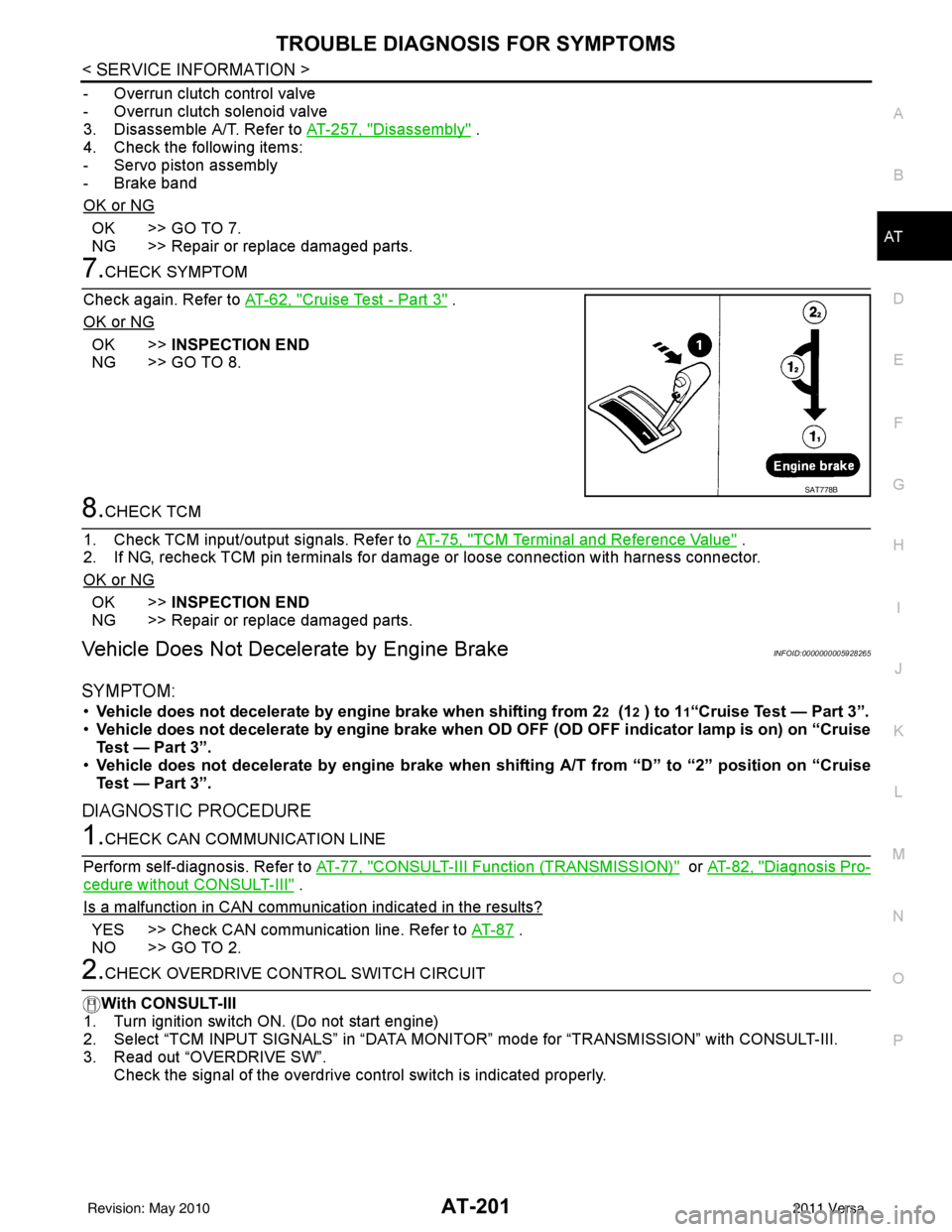
• Vehicle does not decelerate by engine brake when shifting from 22 (12 ) to 11“Cruise Test — Part 3”.
• Vehicle does not decelerate by engi ne brake when OD OFF (OD OFF indicator lamp is on) on “Cruise
Test — Part 3”.
• Vehicle does not decelerate by engi ne brake when shifting A/T from “D” to “2” position on “Cruise
Test — Part 3”.
DIAGNOSTIC PROCEDURE
1.CHECK CAN COMMUNICATION LINE
Perform self-diagnosis. Refer to AT-77, "
CONSULT-III Function (TRANSMISSION)" or AT-82, "Diagnosis Pro-
cedure without CONSULT-III" .
Is a malfunction in CAN communication indicated in the results?
YES >> Check CAN communication line. Refer to AT- 8 7 .
NO >> GO TO 2.
2.CHECK OVERDRIVE CO NTROL SWITCH CIRCUIT
With CONSULT-III
1. Turn ignition switch ON. (Do not start engine)
2. Select “TCM INPUT SIGNALS” in “DATA MONI TOR” mode for “TRANSMISSION” with CONSULT-III.
3. Read out “OVERDRIVE SW”.
Check the signal of the overdrive control switch is indicated properly.
SAT778B
Revision: May 2010 2011 Versa
Page 221 of 3787
AT-204
< SERVICE INFORMATION >
TROUBLE DIAGNOSIS FOR SYMPTOMS
- Overrun clutch solenoid valve
3. Disassemble A/T. Refer to AT-257, "
Disassembly" .
4. Check the following.
- Overrun clutch assembly. Refer to AT-307, "
Forward and Overrun Clutches" .
- Low & reverse brake assembly. Refer to AT-314, "
Low & Reverse Brake" .
OK or NG
OK >> GO TO 10.
NG >> Repair or replace damaged parts.
10.CHECK SYMPTOM
Check again. Refer to AT-62, "
Cruise Test - Part 3" .
OK or NG
OK >> INSPECTION END
NG >> GO TO 11.
11 .CHECK TCM
1. Check TCM input/output signals. Refer to AT-75, "
TCM Terminal and Reference Value" .
2. If NG, recheck TCM pin terminals for damage or loose connection with harness connector.
OK or NG
OK >> INSPECTION END
NG >> Repair or replace damaged parts.
TCM Self-Diagnosis Does Not ActivateINFOID:0000000005928266
SYMPTOM:
OD OFF indicator lamp does not come on in TCM sel f-diagnostic procedure even if the lamp circuit is
good.
DESCRIPTION
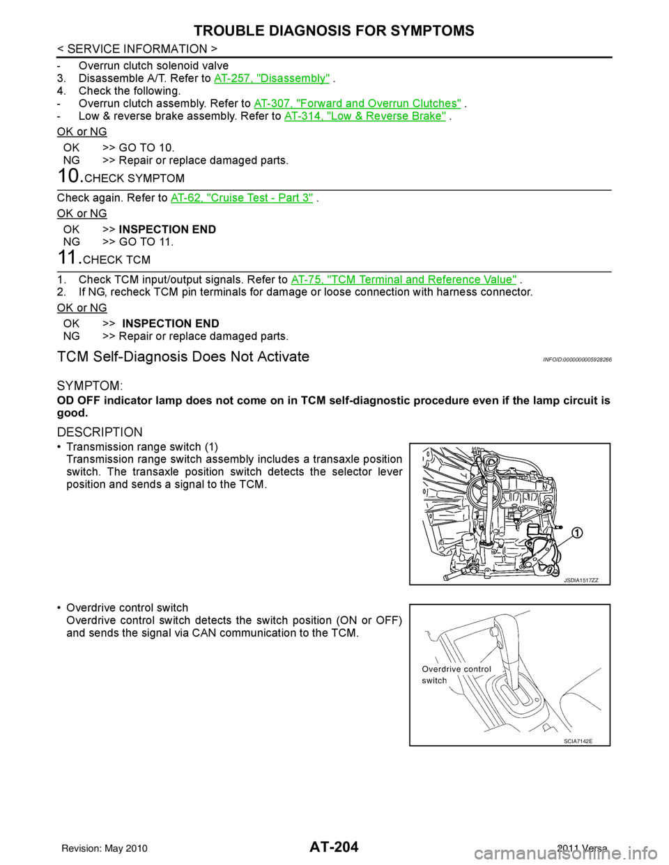
• Transmission range switch (1) Transmission range switch assembly includes a transaxle position
switch. The transaxle position swit ch detects the selector lever
position and sends a signal to the TCM.
• Overdrive control switch Overdrive control switch detects the switch position (ON or OFF)
and sends the signal via CAN communication to the TCM.
JSDIA1517ZZ
SCIA7142E
Revision: May 2010 2011 Versa