2011 NISSAN LATIO turn signal
[x] Cancel search: turn signalPage 2794 of 3787
GW-40
< SERVICE INFORMATION >
POWER WINDOW SYSTEM
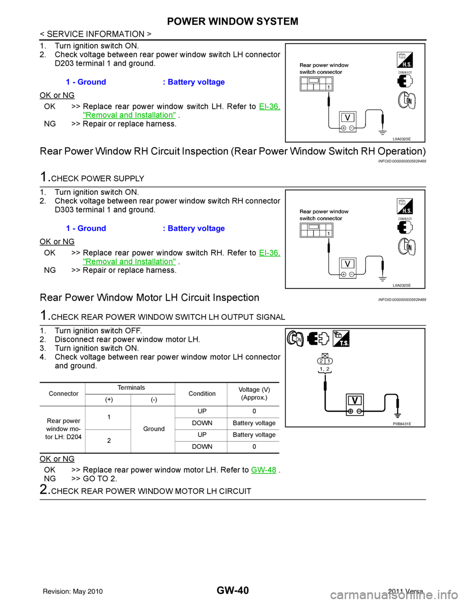
1. Turn ignition switch ON.
2. Check voltage between rear power window switch LH connectorD203 terminal 1 and ground.
OK or NG
OK >> Replace rear power window switch LH. Refer to EI-36,
"Removal and Installation" .
NG >> Repair or replace harness.
Rear Power Window RH Circuit Inspection (R ear Power Window Switch RH Operation)
INFOID:0000000005929488
1.CHECK POWER SUPPLY
1. Turn ignition switch ON.
2. Check voltage between rear power window switch RH connector D303 terminal 1 and ground.
OK or NG
OK >> Replace rear power window switch RH. Refer to EI-36,
"Removal and Installation" .
NG >> Repair or replace harness.
Rear Power Window Motor LH Circuit InspectionINFOID:0000000005929489
1.CHECK REAR POWER WINDOW SWITCH LH OUTPUT SIGNAL
1. Turn ignition switch OFF.
2. Disconnect rear power window motor LH.
3. Turn ignition switch ON.
4. Check voltage between rear power window motor LH connector and ground.
OK or NG
OK >> Replace rear power window motor LH. Refer to GW-48 .
NG >> GO TO 2.
2.CHECK REAR POWER WINDOW MOTOR LH CIRCUIT 1 - Ground : Battery voltage
LIIA0325E
1 - Ground
: Battery voltage
LIIA0325E
ConnectorTe r m i n a l s
ConditionVoltage (V)
(Approx.)
(+) (-)
Rear power
window mo-
tor LH: D204 1
Ground UP
0
DOWN Battery voltage
2 UP Battery voltage
DOWN 0
PIIB6431E
Revision: May 2010 2011 Versa
Page 2796 of 3787
GW-42
< SERVICE INFORMATION >
POWER WINDOW SYSTEM
NG >> Repair or replace harness.
Rear Power Window Motor RH Circuit InspectionINFOID:0000000005929490
1.CHECK REAR POWER WINDOW SWITCH RH OUTPUT SIGNAL
1. Turn ignition switch OFF.
2. Disconnect rear power window motor RH.
3. Turn ignition switch ON.
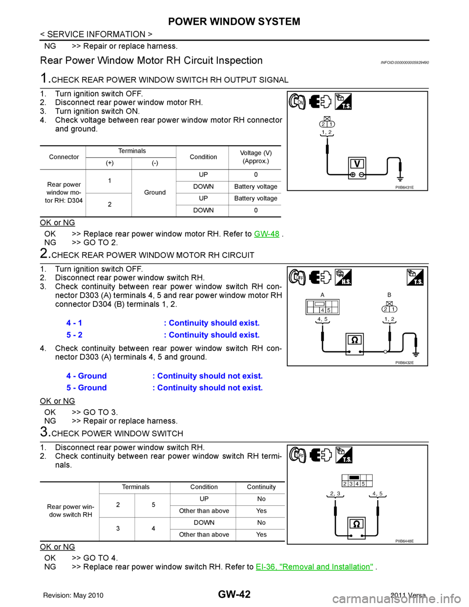
4. Check voltage between rear power window motor RH connector and ground.
OK or NG
OK >> Replace rear power window motor RH. Refer to GW-48 .
NG >> GO TO 2.
2.CHECK REAR POWER WINDOW MOTOR RH CIRCUIT
1. Turn ignition switch OFF.
2. Disconnect rear power window switch RH.
3. Check continuity between rear power window switch RH con- nector D303 (A) terminals 4, 5 and rear power window motor RH
connector D304 (B) terminals 1, 2.
4. Check continuity between rear power window switch RH con- nector D303 (A) terminals 4, 5 and ground.
OK or NG
OK >> GO TO 3.
NG >> Repair or replace harness.
3.CHECK POWER WINDOW SWITCH
1. Disconnect rear power window switch RH.
2. Check continuity between rear power window switch RH termi- nals.
OK or NG
OK >> GO TO 4.
NG >> Replace rear power window switch RH. Refer to EI-36, "
Removal and Installation" .
ConnectorTe r m i n a l s
ConditionVoltage (V)
(Approx.)
(+) (-)
Rear power
window mo-
tor RH: D304 1
Ground UP
0
DOWN Battery voltage
2 UP Battery voltage
DOWN 0
PIIB6431E
4 - 1 : Continuity should exist.
5 - 2 : Continuity should exist.
4 - Ground : Continuity should not exist.
5 - Ground : Continuity should not exist.
PIIB6432E
Rear power win-
dow switch RH Terminals
Condition Continuity
25 UP
No
Other than above Yes
34 DOWN
No
Other than above Yes
PIIB6448E
Revision: May 2010 2011 Versa
Page 2806 of 3787

GW-52
< SERVICE INFORMATION >
REAR WINDOW DEFOGGER
Power is supplied at all times
• through 15A fuses (No. 46 and 47, located in the IPDM E/R)
• to rear window defogger relay
• through 10A fuse [No. 5 (with heated mirrors), located in the fuse block (J/B)]
• to heated mirror relay terminal 3
• through 40A fusible link (letter g , located in the fuse and fusible link box)
• to BCM terminal 70.
With the ignition switch turned to ON or START position, power is supplied
• through ignition relay
• to rear window defogger relay (located in the IPDM E/R)
• through 10A fuse [No. 6, located in the fuse block (J/B)]
• to BCM terminal 38.
Ground is supplied
• to BCM terminal 67 and
• to front air control terminal 8
• through body grounds M57 and M61
• to IPDM E/R terminals 39 and 59
• through body grounds E15 and E24.
When front air control (rear window defogger switch) is turned to ON, ground is supplied
• to BCM terminal 9
• through front air control terminal 3
• through front air control terminal 8
• through body grounds M57 and M61.
Then rear window defogger switch is illuminated.
Then BCM recognizes that rear window defogger switch is turned to ON.
Then it sends rear window defogger switch signals to IPDM E/R via CAN communication (CAN-H, CAN-L).
When IPDM E/R receives rear window defogger switch signals, ground is supplied
• to rear window defogger relay (located in the IPDM E/R)
• through IPDM E/R terminals 39 and 59
• through body grounds E15 and E24
Then rear window defogger relay is energized.
With power and ground supplied, rear window def ogger filaments heat and defog the rear window.
When rear window defogger relay is turned to ON (with heated mirrors), power is supplied
• through heated mirror relay terminal 5
• to door mirror (LH and RH) terminal 1.
Door mirror (LH and RH) is grounded through body grounds M57 and M61.
With power and ground supplied, rear window defogger filaments heat and defog the rear window and door
mirror filaments heat and defog the mirrors.
CAN Communication System DescriptionINFOID:0000000005929499
Refer to LAN-7, "System Description".
Revision: May 2010 2011 Versa
Page 2811 of 3787
REAR WINDOW DEFOGGERGW-57
< SERVICE INFORMATION >
C
DE
F
G H
J
K L
M A
B
GW
N
O P
1. Turn ignition switch OFF.
2. Disconnect BCM and front air control.
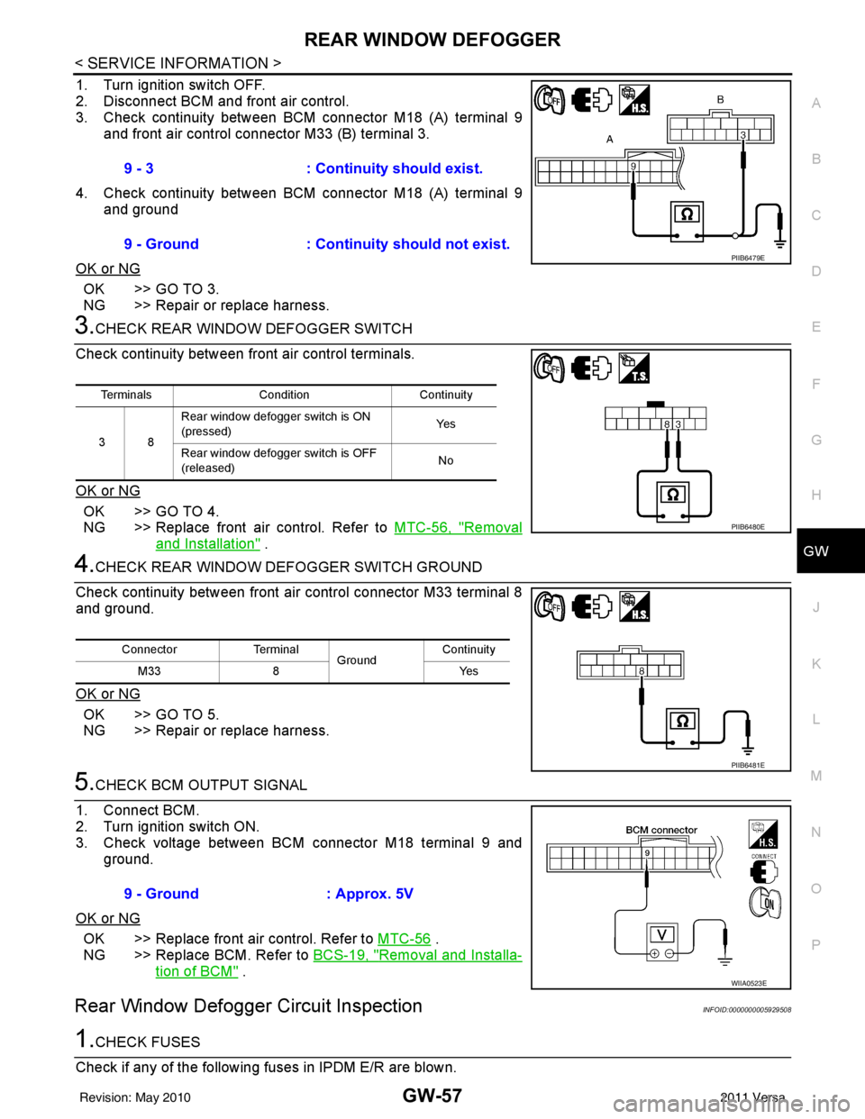
3. Check continuity between BCM connector M18 (A) terminal 9 and front air control connector M33 (B) terminal 3.
4. Check continuity between BCM connector M18 (A) terminal 9 and ground
OK or NG
OK >> GO TO 3.
NG >> Repair or replace harness.
3.CHECK REAR WINDOW DEFOGGER SWITCH
Check continuity between fr ont air control terminals.
OK or NG
OK >> GO TO 4.
NG >> Replace front air control. Refer to MTC-56, "
Removal
and Installation" .
4.CHECK REAR WINDOW DEFOGGER SWITCH GROUND
Check continuity between front air control connector M33 terminal 8
and ground.
OK or NG
OK >> GO TO 5.
NG >> Repair or replace harness.
5.CHECK BCM OUTPUT SIGNAL
1. Connect BCM.
2. Turn ignition switch ON.
3. Check voltage between BCM connector M18 terminal 9 and ground.
OK or NG
OK >> Replace front air control. Refer to MTC-56 .
NG >> Replace BCM. Refer to BCS-19, "
Removal and Installa-
tion of BCM" .
Rear Window Defogger Circuit InspectionINFOID:0000000005929508
1.CHECK FUSES
Check if any of the following fuses in IPDM E/R are blown. 9 - 3
: Continuity should exist.
9 - Ground : Continuity should not exist.
PIIB6479E
Terminals Condition Continuity
38 Rear window defogger switch is ON
(pressed)
Ye s
Rear window defogger switch is OFF
(released) No
PIIB6480E
Connector
Terminal
Ground Continuity
8Y es
M33
PIIB6481E
9 - Ground : Approx. 5V
WIIA0523E
Revision: May 2010 2011 Versa
Page 2813 of 3787
REAR WINDOW DEFOGGERGW-59
< SERVICE INFORMATION >
C
DE
F
G H
J
K L
M A
B
GW
N
O P
OK or NG
OK >> GO TO 5.
NG >> Repair or replace harness.
5.CHECK CONDENSER-1
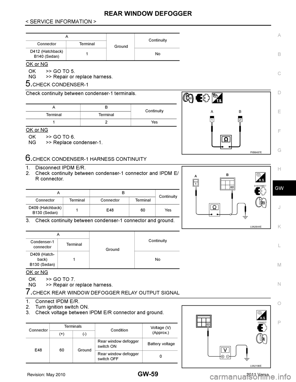
Check continuity between condenser-1 terminals.
OK or NG
OK >> GO TO 6.
NG >> Replace condenser-1.
6.CHECK CONDENSER-1 HARNESS CONTINUITY
1. Disconnect IPDM E/R.
2. Check continuity between condenser-1 connector and IPDM E/ R connector.
3. Check continuity between condenser-1 connector and ground.
OK or NG
OK >> GO TO 7.
NG >> Repair or replace harness.
7.CHECK REAR WINDOW DEFOGGER RELAY OUTPUT SIGNAL
1. Connect IPDM E/R.
2. Turn ignition switch ON.
3. Check voltage between IPDM E/R connector and ground.
A
GroundContinuity
Connector Terminal
D412 (Hatchback) B140 (Sedan) 1N
o
AB
Continuity
Te r m i n a l Te r m i n a l
12Y es
PIIB6487E
AB
Continuity
Connector Terminal Connector Terminal
D409 (Hatchback) B130 (Sedan) 1
E48 60 Yes
A GroundContinuity
Condenser-1
connector Te r m i n a l
D409 (Hatch- back)
B130 (Sedan) 1N
o
LIIA2644E
ConnectorTe r m i n a l s
ConditionVoltage (V)
(Approx.)
(+) (-)
E48 60 Ground Rear window defogger
switch ON
Battery voltage
Rear window defogger
switch OFF 0
LIIA2190E
Revision: May 2010
2011 Versa
Page 2837 of 3787
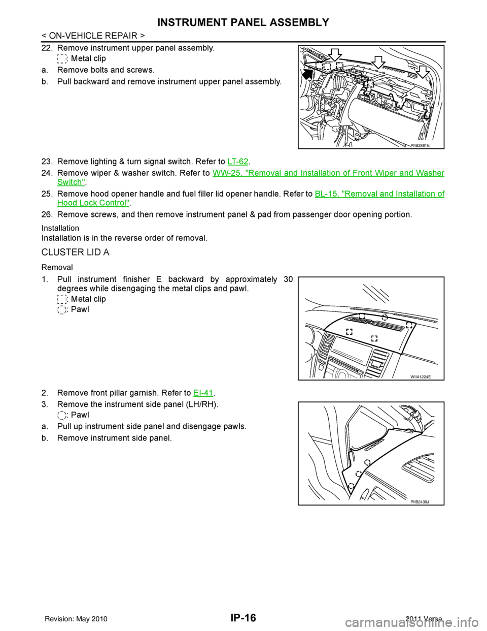
IP-16
< ON-VEHICLE REPAIR >
INSTRUMENT PANEL ASSEMBLY
22. Remove instrument upper panel assembly.: Metal clip
a. Remove bolts and screws.
b. Pull backward and remove instrument upper panel assembly.
23. Remove lighting & turn signal switch. Refer to LT- 6 2
.
24. Remove wiper & washer switch. Refer to WW-25, "
Removal and Installation of Front Wiper and Washer
Switch".
25. Remove hood opener handle and fuel filler lid opener handle. Refer to BL-15, "
Removal and Installation of
Hood Lock Control".
26. Remove screws, and then remove instrument panel & pad from passenger door opening portion.
Installation
Installation is in the reverse order of removal.
CLUSTER LID A
Removal
1. Pull instrument finisher E backward by approximately 30
degrees while disengaging the metal clips and pawl.
: Metal clip
: Pawl
2. Remove front pillar garnish. Refer to EI-41
.
3. Remove the instrument side panel (LH/RH). : Pawl
a. Pull up instrument side panel and disengage pawls.
b. Remove instrument side panel.
PIIB2881E
WIIA1224E
PIIB2439J
Revision: May 2010 2011 Versa
Page 2856 of 3787
![NISSAN LATIO 2011 Service Repair Manual LAN-10
< SERVICE INFORMATION >[CAN FUNDAMENTAL]
TROUBLE DIAGNOSIS
TROUBLE DIAGNOSIS
Condition of Error DetectionINFOID:0000000005928519
DTC of CAN communication is indicated on SELF-DIAG
RESULTS on C NISSAN LATIO 2011 Service Repair Manual LAN-10
< SERVICE INFORMATION >[CAN FUNDAMENTAL]
TROUBLE DIAGNOSIS
TROUBLE DIAGNOSIS
Condition of Error DetectionINFOID:0000000005928519
DTC of CAN communication is indicated on SELF-DIAG
RESULTS on C](/manual-img/5/57357/w960_57357-2855.png)
LAN-10
< SERVICE INFORMATION >[CAN FUNDAMENTAL]
TROUBLE DIAGNOSIS
TROUBLE DIAGNOSIS
Condition of Error DetectionINFOID:0000000005928519
DTC of CAN communication is indicated on SELF-DIAG
RESULTS on CONSULT-III if a CAN communication
signal is not transmitted or received between units for 2 seconds or more.
NOTE:
DTCs of CAN communication are as follows:
• U0101
• U0140
• U0164
• U1000
• U1001
CAN COMMUNICATION SYSTEM ERROR
• CAN communication line open (CAN-H, CAN-L, or both)
• CAN communication line short (ground, between CAN communication lines, other harnesses)
• Error of CAN communication control circuit of the unit connected to CAN communication line
WHEN DTC OF CAN COMMUNICATION IS INDICATED EVEN THOUGH CAN COMMUNICATION
SYSTEM IS NORMAL
• Removal/installation of parts: Error may be detec ted when removing and installing CAN communication unit
and related parts while turning the ignition switch ON. (A DTC except for CAN communication may be
detected.)
• Fuse blown out (removed): CAN co mmunication of the unit may cease.
• Voltage drop: Error may be detected if voltage drops due to discharged battery when turning the ignition switch ON (Depending on the control unit which carries out CAN communication).
• Error may be detected if the power supply circuit of the control unit, which carries out CAN communication, malfunctions (Depending on the control unit which carries out CAN communication).
• Error may be detected if reprogramming is not completed normally.
CAUTION:
CAN communication system is normal if DTC of CAN communication is indicated on SELF-DIAG
RESULTS of CONSULT-III under th e above conditions. Erase the memo ry of the self-diagnosis of each
unit.
Symptom When Error Occurs in CAN Communication SystemINFOID:0000000005928520
In CAN communication system, multiple units mutually transmit and receive signals. Each unit cannot transmit
and receive signals if any error occurs on CAN communicati on line. Under this condition, multiple control units
related to the root cause malfunction or go into fail-safe mode.
ERROR EXAMPLE
NOTE:
• Each vehicle differs in symptom of each unit under fail-safe mode and CAN communication line wiring.
• Refer to LAN-22, "
Abbreviation List" for the unit abbreviation.
Revision: May 2010 2011 Versa
Page 2858 of 3787
![NISSAN LATIO 2011 Service Repair Manual LAN-12
< SERVICE INFORMATION >[CAN FUNDAMENTAL]
TROUBLE DIAGNOSIS
NOTE:
• When data link connector branch line is open, transmission and reception of CAN communication signals
are not affected. Ther NISSAN LATIO 2011 Service Repair Manual LAN-12
< SERVICE INFORMATION >[CAN FUNDAMENTAL]
TROUBLE DIAGNOSIS
NOTE:
• When data link connector branch line is open, transmission and reception of CAN communication signals
are not affected. Ther](/manual-img/5/57357/w960_57357-2857.png)
LAN-12
< SERVICE INFORMATION >[CAN FUNDAMENTAL]
TROUBLE DIAGNOSIS
NOTE:
• When data link connector branch line is open, transmission and reception of CAN communication signals
are not affected. Therefore, no symptoms occur. However, be sure to repair malfunctioning circuit.
• The model (all units on CAN communication system are Diag on CAN) cannot perform CAN diagnosis with
CONSULT-III if the following error occu rs. The error is judged by the symptom.
Example: Main Line Between Data Link Connector and ABS Actuator and Electric Un it (Control Unit) Open Circuit
Unit name Symptom
ECM
Normal operation.
BCM
EPS control unit
Combination meter
ABS actuator and electric unit (control unit)
TCM
IPDM E/R
Error Difference of symptom
Data link connector branch line open circuit Normal operation.
CAN-H, CAN-L harness short-circuit Most of the units which are connected to the CAN communication
system enter fail-safe mode or are deactivated.
SKIB8740E
Unit name
Symptom
ECM Engine torque limiting is affected, and shift harshness increases.
BCM • Reverse warning chime does not sound.
• The front wiper moves under continuous operation mode even though the front wip-
er switch being in the intermittent position.
EPS control unit The steering effort increases.
Combination meter • The shift position indicator and OD OFF indicator turn OFF.
• The speedometer is inoperative.
• The odo/trip meter stops.
ABS actuator and electric unit (control unit) Normal operation.
TCM No impact on operation.
IPDM E/R When the ignition switch is ON,
• The headlamps (Lo) turn ON.
• The cooling fan continues to rotate.
Revision: May 2010
2011 Versa