2011 NISSAN LATIO length
[x] Cancel search: lengthPage 2621 of 3787
![NISSAN LATIO 2011 Service Repair Manual SERVICE DATA AND SPECIFICATIONS (SDS)EM-231
< SERVICE INFORMATION > [MR18DE]
C
D
E
F
G H
I
J
K L
M A
EM
NP
O
Unit: mm (in)
VA LV E
Va l v e Ti m i n g
Unit: degree
( ): Valve timing control “ON”
NISSAN LATIO 2011 Service Repair Manual SERVICE DATA AND SPECIFICATIONS (SDS)EM-231
< SERVICE INFORMATION > [MR18DE]
C
D
E
F
G H
I
J
K L
M A
EM
NP
O
Unit: mm (in)
VA LV E
Va l v e Ti m i n g
Unit: degree
( ): Valve timing control “ON”](/manual-img/5/57357/w960_57357-2620.png)
SERVICE DATA AND SPECIFICATIONS (SDS)EM-231
< SERVICE INFORMATION > [MR18DE]
C
D
E
F
G H
I
J
K L
M A
EM
NP
O
Unit: mm (in)
VA LV E
Va l v e Ti m i n g
Unit: degree
( ): Valve timing control “ON”
Valve Dimensions
Unit: mm (in)
Items
StandardLimit
Head surface distortion —0.1 (0.004)
Normal cylinder head height (H) 130.9 (5.15)—
Groove of No. 1 journal 4.000 - 4.300 (0.1575 - 0.1587) —
PBIC0924E
Valve timing
abcde f
212 224-8 (32) 52 (12) 725
PBIC4542E
Valve head diameter (D) Intake 33.8 - 34.1 (1.331 - 1.343)
Exhaust
27.6 - 27.9 (1.087 - 1.098)
Valve length (L) Intake
106.27 (4.184)
Exhaust 105.26 (4.144)
SEM188A
Revision: May 2010 2011 Versa
Page 2623 of 3787
![NISSAN LATIO 2011 Service Repair Manual SERVICE DATA AND SPECIFICATIONS (SDS)EM-233
< SERVICE INFORMATION > [MR18DE]
C
D
E
F
G H
I
J
K L
M A
EM
NP
O
*: Always check with the Parts Department for the latest parts information
Va l v e Sp r i NISSAN LATIO 2011 Service Repair Manual SERVICE DATA AND SPECIFICATIONS (SDS)EM-233
< SERVICE INFORMATION > [MR18DE]
C
D
E
F
G H
I
J
K L
M A
EM
NP
O
*: Always check with the Parts Department for the latest parts information
Va l v e Sp r i](/manual-img/5/57357/w960_57357-2622.png)
SERVICE DATA AND SPECIFICATIONS (SDS)EM-233
< SERVICE INFORMATION > [MR18DE]
C
D
E
F
G H
I
J
K L
M A
EM
NP
O
*: Always check with the Parts Department for the latest parts information
Va l v e Sp r i n g
Valve Lifter
Unit: mm (in)
Valve Guide
Unit: mm (in)
Valve Seal
3.44 (0.1354)
344
3.46 (0.1362) 346
3.48 (0.1370) 348
3.50 (0.1378) 350
Thickness mm (in)
Identification mark*
ItemsIntake Exhaust
Free height 44.90 - 45.10 mm (1.7677 - 1.7755 in) 45.74 - 45.94 mm (1.8007 - 1.8086 in)
Installation height 35.30 mm (1.390 in) 35.30 mm (1.390 in)
Installation load 153 - 173 N (15.6 - 17.6 kg, 34 - 39 lb) 139 - 157 N (14.2 - 16.0 kg, 31 - 35 lb)
Height during valve open 26.36 mm (1.0377 in) 27.80 mm (1.0944 in)
Load with valve open 335 - 377 N (34.2 - 38.5 kg, 75 - 85 lb) 266 - 297 N (27.1 - 30.3 kg, 60 - 67 lb)
Identification color WhiteOrange
Squareness [Limit] 1.9 mm (0.075 in)
Items Standard
Valve lifter outer diameter Intake
33.977 - 33.987 (1.3377 - 1.3381)
Exhaust 29.977 - 29.987 (1.1802 - 1.1806)
Valve lifter hole diameter Intake
34.000 - 34.021 (1.3386 - 1.3394)
Exhaust 30.000 - 30.021 (1.1811 - 1.1819)
Valve lifter clearance 0.013 - 0.044 (0.0005 - 0.0017)
ItemsStandard partService part
Va l v e g u i d e Outer diameter
9.523 - 9.534 (0.3749 - 0.3754) 9.723 - 9.734 (0.3828 - 0.3832)
Inner diameter (Finished size) 5.500 - 5.518 (0.2165 - 0.2172)
Cylinder head valve guide hole diameter 9.475 - 9.496 (0.3730 - 0.3739) 9.675 - 9.696 (0.3809 - 0.3817)
Interference fit of valve guide 0.027 - 0.059 (0.0011 - 0.0023)
Items StandardLimit
Valve guide clearance Intake
0.020 - 0.053 (0.0008 - 0.0021)
0.1 (0.004)
Exhaust 0.030 - 0.063 (0.0012 - 0.0025)
Projection length (L) 13.35 - 13.65 (0.526 - 0.537)
PBIC0184E
Revision: May 2010 2011 Versa
Page 2657 of 3787
FRONT DRIVE SHAFTFAX-15
< SERVICE INFORMATION >
CEF
G H
I
J
K L
M A
B
FA X
N
O P
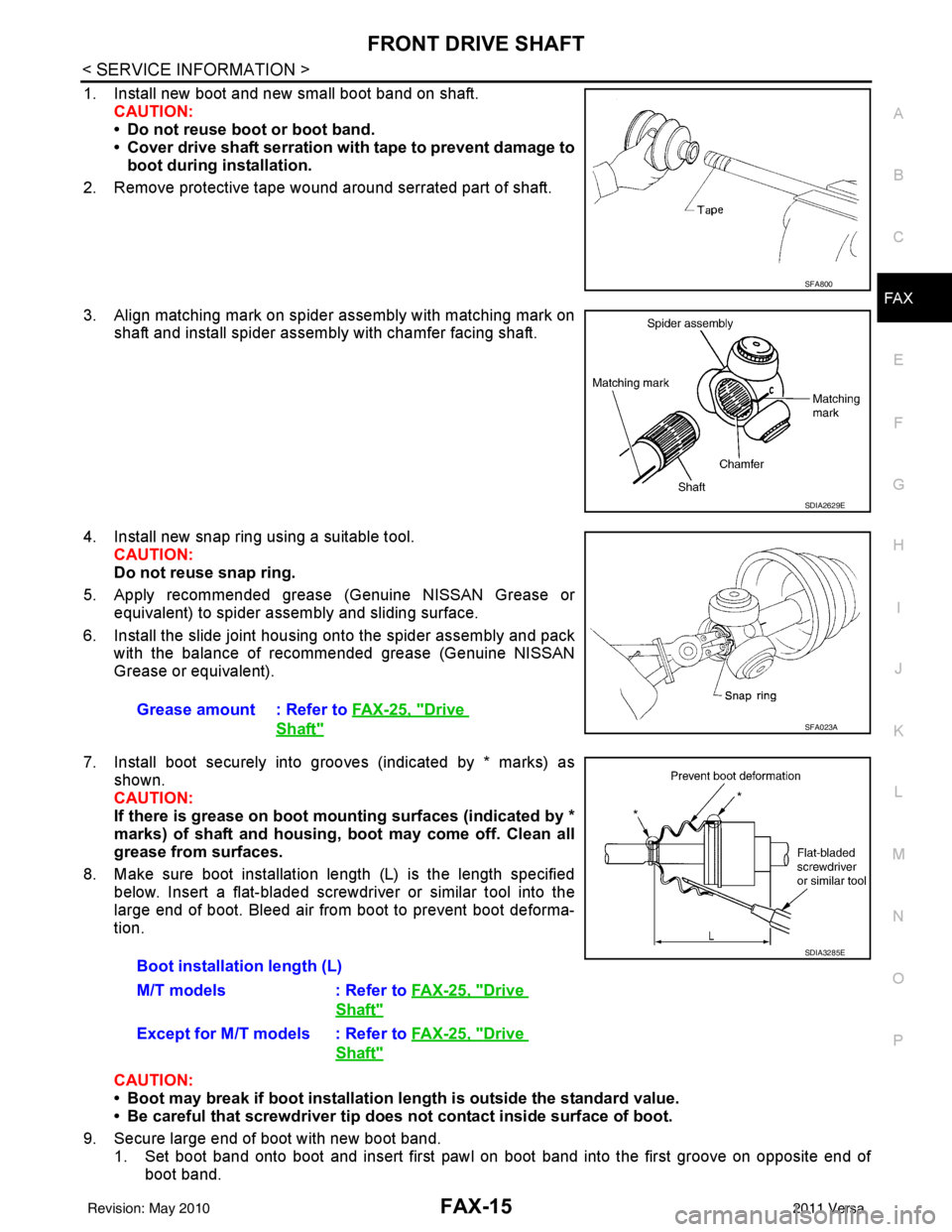
1. Install new boot and new small boot band on shaft. CAUTION:
• Do not reuse boot or boot band.
• Cover drive shaft serration with tape to prevent damage toboot during installation.
2. Remove protective tape wound around serrated part of shaft.
3. Align matching mark on spider assembly with matching mark on shaft and install spider assembly with chamfer facing shaft.
4. Install new snap ring using a suitable tool. CAUTION:
Do not reuse snap ring.
5. Apply recommended grease (Genuine NISSAN Grease or equivalent) to spider assembly and sliding surface.
6. Install the slide joint housing onto the spider assembly and pack with the balance of recommended grease (Genuine NISSAN
Grease or equivalent).
7. Install boot securely into grooves (indicated by * marks) as shown.
CAUTION:
If there is grease on boot mounting surfaces (indicated by *
marks) of shaft and housing, boot may come off. Clean all
grease from surfaces.
8. Make sure boot installation length (L) is the length specified below. Insert a flat-bladed screwdriver or similar tool into the
large end of boot. Bleed air from boot to prevent boot deforma-
tion.
CAUTION:
• Boot may break if boot installation le ngth is outside the standard value.
• Be careful that screwdriver tip does not contact inside surface of boot.
9. Secure large end of boot with new boot band. 1. Set boot band onto boot and insert first pawl on boot band into the first groove on opposite end of boot band.
SFA800
SDIA2629E
Grease amount : Refer to FAX-25, "Drive
Shaft" SFA023A
Boot installation length (L)
M/T models : Refer to FAX-25, "
Drive
Shaft"
Except for M/T models : Refer to FAX-25, "Drive
Shaft"
SDIA3285E
Revision: May 2010 2011 Versa
Page 2659 of 3787
FRONT DRIVE SHAFTFAX-17
< SERVICE INFORMATION >
CEF
G H
I
J
K L
M A
B
FA X
N
O P
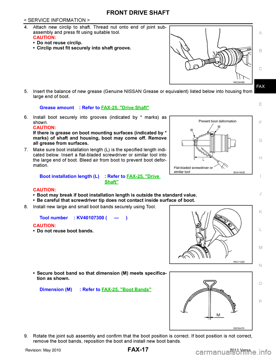
4. Attach new circlip to shaft. Thread nut onto end of joint sub- assembly and press fit using suitable tool.
CAUTION:
• Do not reuse circlip.
• Circlip must fit securely into shaft groove.
5. Insert the balance of new grease (Genuine NISSAN Grease or equivalent) listed below into housing from
large end of boot.
6. Install boot securely into grooves (indicated by * marks) as shown.
CAUTION:
If there is grease on boot mounting surfaces (indicated by *
marks) of shaft and housing, boot may come off. Remove
all grease from surfaces.
7. Make sure boot installation length (L) is the specified length indi- cated below. Insert a flat-bladed screwdriver or similar tool into
the large end of boot. Bleed air from boot to prevent boot defor-
mation.
CAUTION:
• Boot may break if boot installation le ngth is outside the standard value.
• Be careful that screwdriver tip does not contact inside surface of boot.
8. Install new large and small boot bands securely using Tool.
CAUTION:
• Do not reuse boot bands.
• Secure boot band so that dimension (M) meets specifica-tion as shown.
9. Rotate the joint sub assembly and confirm that the boot position is correct. If boot position is not correct,
remove the boot bands, reposition the boot and install new boot bands.
RAC0049D
Grease amount : Refer to FAX-25, "Drive Shaft"
Boot installation length (L) : Refer to FAX-25, "
Drive
Shaft"
Tool number : KV40107300 ( — )
SDIA1505E
RAC1133D
Dimension (M) : Refer to FAX-25, "Boot Bands"
DSF0047D
Revision: May 2010 2011 Versa
Page 2663 of 3787

FRONT DRIVE SHAFTFAX-21
< SERVICE INFORMATION >
CEF
G H
I
J
K L
M A
B
FA X
N
O P
1. Install new boot and new small boot band on shaft. CAUTION:
• Do not reuse boot or boot band.
• Cover drive shaft serration with tape to prevent damage toboot during installation.
2. Remove protective tape wound around serrated part of shaft.
3. Align matching mark on spider assembly with matching mark on shaft and install spider assembly with chamfer facing shaft.
4. Install new snap ring using a suitable tool. CAUTION:
Do not reuse snap ring.
5. Apply recommended grease (Genuine NISSAN Grease or equivalent) to spider assembly and sliding surface.
6. Install the slide joint housing onto the spider assembly and pack with the balance of recommended grease (Genuine NISSAN
Grease or equivalent).
7. Install boot securely into grooves (indicated by * marks) as shown.
CAUTION:
If there is grease on boot mounting surfaces (indicated by *
marks) of shaft and housing, boot may come off. Clean all
grease from surfaces.
8. Make sure boot installation length (L) is the length specified below. Insert a flat-bladed screwdriver or similar tool into the
large end of boot. Bleed air from boot to prevent boot deforma-
tion.
CAUTION:
• Boot may break if boot installation le ngth is outside the standard value.
• Be careful that screwdriver tip does not contact inside surface of boot.
9. Secure large end of boot with new boot band. 1. Set boot band onto boot and insert first pawl on boot band into the first groove on opposite end of boot band.
SFA800
SDIA2629E
Grease amount : Refer to FAX-25, "Drive
Shaft"SFA023A
Boot installation length (L)
A/T models : Refer to FAX-25, "
Drive
Shaft"
Except for A/T models : Refer to FAX-25, "Drive
Shaft"
SDIA3285E
Revision: May 2010 2011 Versa
Page 2665 of 3787
FRONT DRIVE SHAFTFAX-23
< SERVICE INFORMATION >
CEF
G H
I
J
K L
M A
B
FA X
N
O P
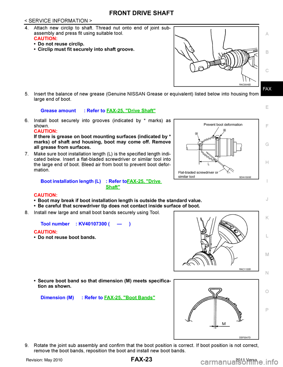
4. Attach new circlip to shaft. Thread nut onto end of joint sub- assembly and press fit using suitable tool.
CAUTION:
• Do not reuse circlip.
• Circlip must fit securely into shaft groove.
5. Insert the balance of new grease (Genuine NISSAN Grease or equivalent) listed below into housing from
large end of boot.
6. Install boot securely into grooves (indicated by * marks) as shown.
CAUTION:
If there is grease on boot mounting surfaces (indicated by *
marks) of shaft and housing, boot may come off. Remove
all grease from surfaces.
7. Make sure boot installation length (L) is the specified length indi- cated below. Insert a flat-bladed screwdriver or similar tool into
the large end of boot. Bleed air from boot to prevent boot defor-
mation.
CAUTION:
• Boot may break if boot installation le ngth is outside the standard value.
• Be careful that screwdriver tip does not contact inside surface of boot.
8. Install new large and small boot bands securely using Tool.
CAUTION:
• Do not reuse boot bands.
• Secure boot band so that dimension (M) meets specifica-tion as shown.
9. Rotate the joint sub assembly and confirm that the boot position is correct. If boot position is not correct,
remove the boot bands, reposition the boot and install new boot bands.
RAC0049D
Grease amount : Refer to FAX-25, "Drive Shaft"
Boot installation length (L) : Refer toFAX-25, "Drive
Shaft"
Tool number : KV40107300 ( — )
SDIA1505E
RAC1133D
Dimension (M) : Refer to FAX-25, "Boot Bands"
DSF0047D
Revision: May 2010 2011 Versa
Page 2667 of 3787
SERVICE DATA AND SPECIFICATIONS (SDS)FAX-25
< SERVICE INFORMATION >
CEF
G H
I
J
K L
M A
B
FA X
N
O P
SERVICE DATA AND SPECIFICATIONS (SDS)
Wheel BearingINFOID:0000000005931075
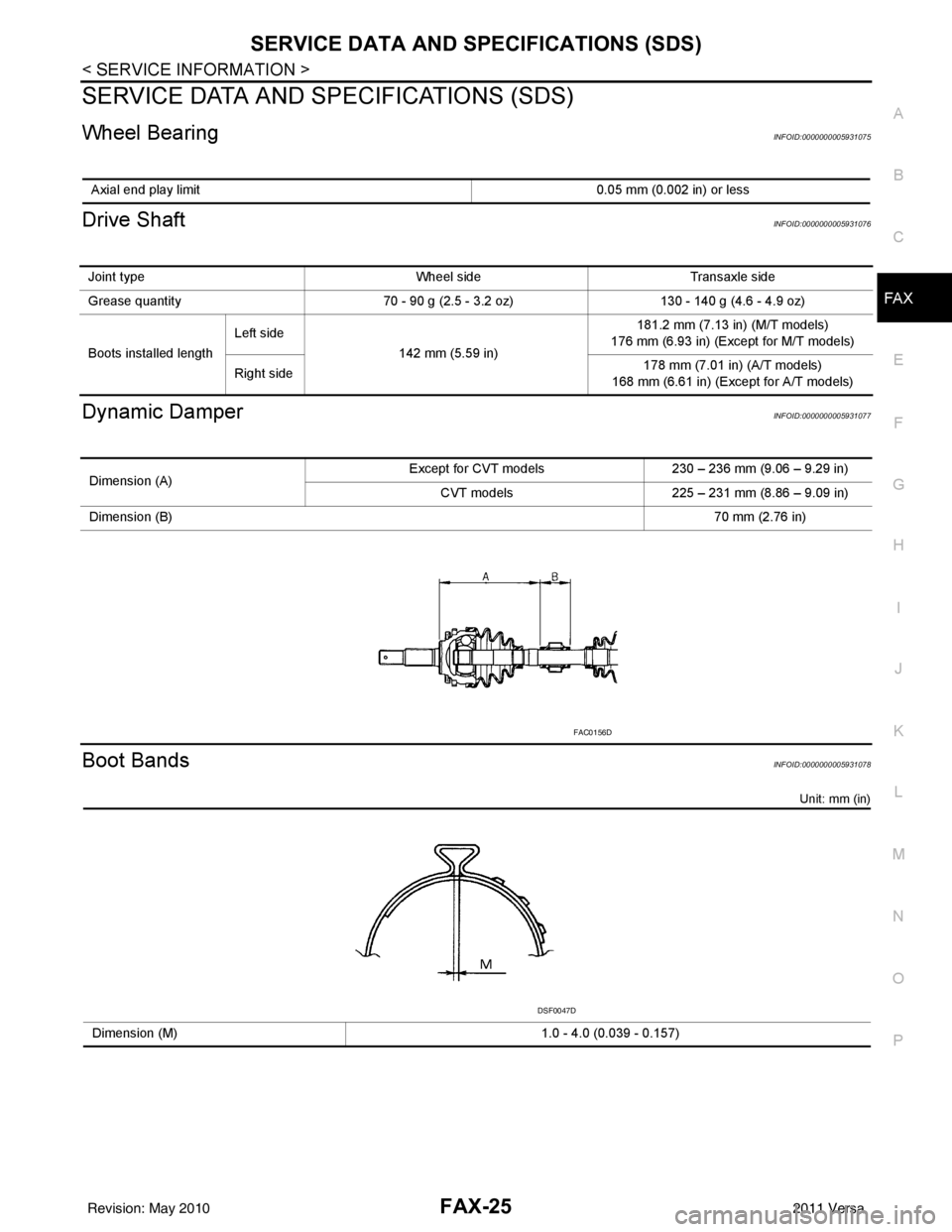
Drive ShaftINFOID:0000000005931076
Dynamic DamperINFOID:0000000005931077
Boot BandsINFOID:0000000005931078
Unit: mm (in)
Axial end play limit 0.05 mm (0.002 in) or less
Joint typeWheel sideTransaxle side
Grease quantity 70 - 90 g (2.5 - 3.2 oz)130 - 140 g (4.6 - 4.9 oz)
Boots installed length Left side
142 mm (5.59 in) 181.2 mm (7.13 in) (M/T models)
176 mm (6.93 in) (Except for M/T models)
Right side 178 mm (7.01 in) (A/T models)
168 mm (6.61 in) (Exc ept for A/T models)
Dimension (A) Except for CVT models
230 – 236 mm (9.06 – 9.29 in)
CVT models 225 – 231 mm (8.86 – 9.09 in)
Dimension (B) 70 mm (2.76 in)
FAC0156D
Dimension (M)1.0 - 4.0 (0.039 - 0.157)
DSF0047D
Revision: May 2010 2011 Versa
Page 2680 of 3787
FUEL TANKFL-13
< SERVICE INFORMATION >
C
DE
F
G H
I
J
K L
M A
FL
NP
O
EVAP Canister
1. Check the connection for damage or any foreign materials.
2. Align the connector with the tube, then insert the c
onnector straight into the tube until a “click” sound is
heard.
3. After connecting, make sure that the connection is secure. • Pull the tube and the connector to make sure they are securely connected.
Fuel Tank Bands
Install the fuel tank bands in the proper position by referring to the identification stamp mark “R” and “L” on the
end
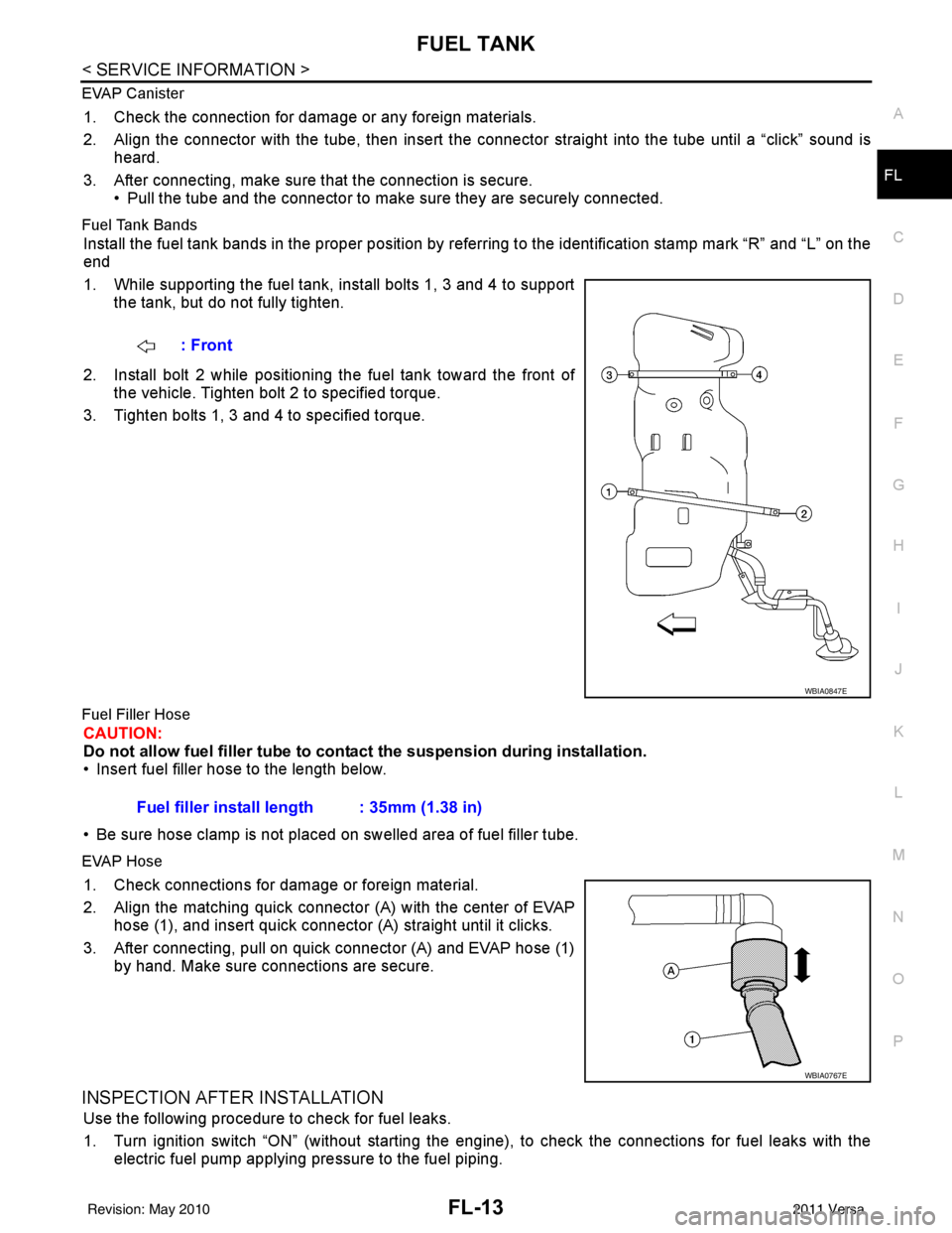
1. While supporting the fuel tank, install bolts 1, 3 and 4 to supportthe tank, but do not fully tighten.
2. Install bolt 2 while positioning the fuel tank toward the front of the vehicle. Tighten bolt 2 to specified torque.
3. Tighten bolts 1, 3 and 4 to specified torque.
Fuel Filler Hose
CAUTION:
Do not allow fuel filler tube to cont act the suspension during installation.
• Insert fuel filler hose to the length below.
• Be sure hose clamp is not placed on swelled area of fuel filler tube.
EVAP Hose
1. Check connections for damage or foreign material.
2. Align the matching quick connector (A) with the center of EVAP
hose (1), and insert quick connector (A) straight until it clicks.
3. After connecting, pull on quick connector (A) and EVAP hose (1) by hand. Make sure connections are secure.
INSPECTION AFTER INSTALLATION
Use the following procedure to check for fuel leaks.
1. Turn ignition switch “ON” (without starting the engi ne), to check the connections for fuel leaks with the
electric fuel pump applying pressure to the fuel piping. : Front
WBIA0847E
Fuel filler install length : 35mm (1.38 in)
WBIA0767E
Revision: May 2010
2011 Versa