Page 327 of 3787

AT-310
< SERVICE INFORMATION >
REPAIR FOR COMPONENT PARTS
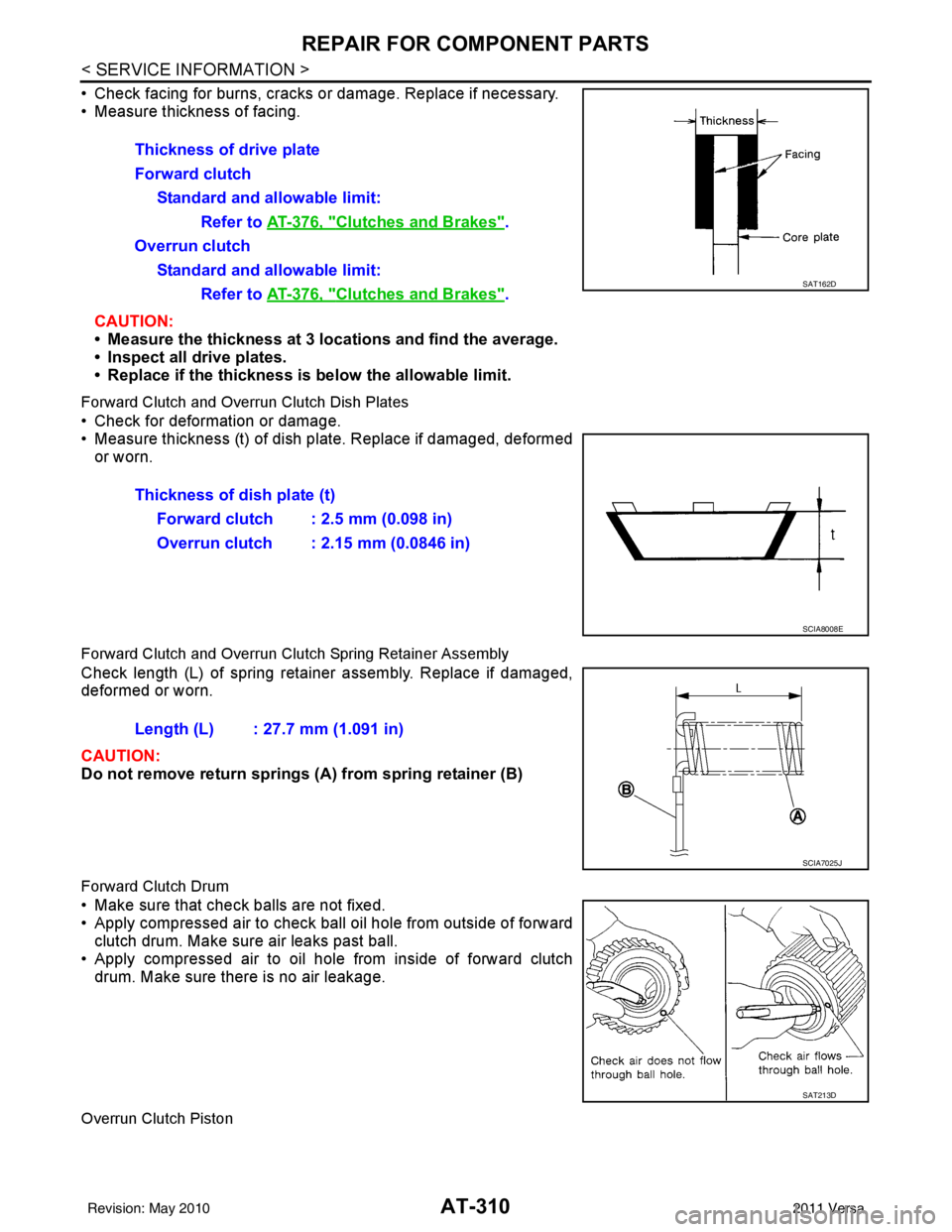
• Check facing for burns, cracks or damage. Replace if necessary.
• Measure thickness of facing.CAUTION:
• Measure the thickness at 3 locations and find the average.
• Inspect all drive plates.
• Replace if the thickness is below the allowable limit.
Forward Clutch and Overrun Clutch Dish Plates
• Check for deformation or damage.
• Measure thickness (t) of dish pl ate. Replace if damaged, deformed
or worn.
Forward Clutch and Overrun Clutch Spring Retainer Assembly
Check length (L) of spring retainer assembly. Replace if damaged,
deformed or worn.
CAUTION:
Do not remove return springs (A ) from spring retainer (B)
Forward Clutch Drum
• Make sure that check balls are not fixed.
• Apply compressed air to check ball oil hole from outside of forward
clutch drum. Make sure air leaks past ball.
• Apply compressed air to oil hole from inside of forward clutch drum. Make sure there is no air leakage.
Overrun Clutch Piston
Thickness of drive plate
Forward clutch
Standard and allowable limit: Refer to AT-376, "
Clutches and Brakes".
Overrun clutch Standard and allowable limit: Refer to AT-376, "
Clutches and Brakes".SAT162D
Thickness of dish plate (t)
Forward clutch : 2.5 mm (0.098 in)
Overrun clutch : 2.15 mm (0.0846 in)
SCIA8008E
Length (L) : 27.7 mm (1.091 in)
SCIA7025J
SAT213D
Revision: May 2010 2011 Versa
Page 333 of 3787
AT-316
< SERVICE INFORMATION >
REPAIR FOR COMPONENT PARTS
• Check facing for burns, cracks or damage. Replace if necessary.
• Measure thickness of facing.CAUTION:
• Measure the thickness at 3 locations and find the average.
• Inspect all drive plates.
• Replace if the thickness is below the allowable limit.
Low & Reverse Brake Dish Plates
• Check for deformation or damage.
• Measure thickness (t) of dish pl ate. Replace if damaged, deformed
or worn.
Low & Reverse Brake Spring Retainer Assembly
Check length (L) of spring retainer assembly. Replace if damaged,
deformed or worn.
CAUTION:
Do not remove return springs (A ) from spring retainer (B)
ASSEMBLY
1. Install seal lip (1) and D-ring (2) on low & reverse brake piston
(3).Thickness of drive plate
Standard and allowable limit: Refer to AT-376, "
Clutches and Brakes".
SAT162D
Thickness of dish plate (t) : 2.93 mm (0.1154 in)
SCIA8008E
Length (L) : 26.3 mm (1.035 in)
SCIA7025J
SCIA6516J
Revision: May 2010 2011 Versa
Page 352 of 3787
REPAIR FOR COMPONENT PARTSAT-335
< SERVICE INFORMATION >
DE
F
G H
I
J
K L
M A
B
AT
N
O P
• Check each return spring for damage or deformation. Also mea- sure free length. Refer to AT-378, "
Band Servo".
• Replace springs if deformed or fatigued.
ASSEMBLY
1. Install D-rings to band servo piston.
2. Install band servo thrust washer (4), band servo piston (3), OD servo return spring (2) and spring retainer (1) to band servo pis-
ton stem (5).
3. Place band servo piston stem (1) on a wooden block, and install E-ring (2) to band servo piston stem (1) while pressing spring
retainer (3) downward.
4. Install O-ring to servo piston retainer.
SAT138D
SCIA3688E
SCIA7054E
SCIA7056E
Revision: May 2010 2011 Versa
Page 367 of 3787

AT-350
< SERVICE INFORMATION >
ASSEMBLY
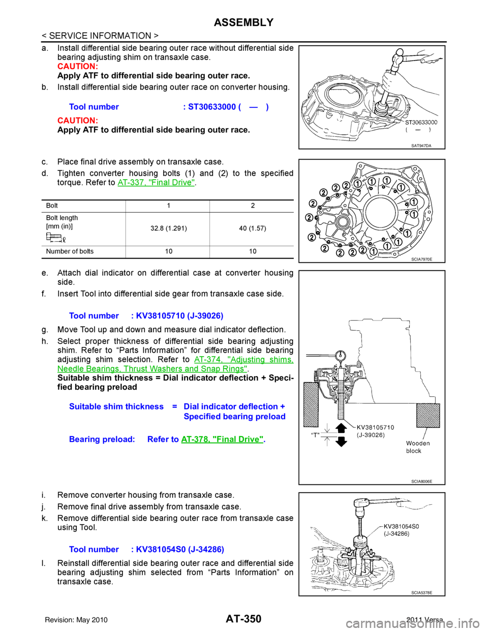
a. Install differential side bearing outer race without differential sidebearing adjusting shim on transaxle case.
CAUTION:
Apply ATF to differential side bearing outer race.
b. Install differential side bearing outer race on converter housing.
CAUTION:
Apply ATF to differential side bearing outer race.
c. Place final drive assembly on transaxle case.
d. Tighten converter housing bolts (1) and (2) to the specified torque. Refer to AT-337, "
Final Drive".
e. Attach dial indicator on differential case at converter housing side.
f. Insert Tool into differential side gear from transaxle case side.
g. Move Tool up and down and measure dial indicator deflection.
h. Select proper thickness of differential side bearing adjusting shim. Refer to “Parts Information” for differential side bearing
adjusting shim selection. Refer to AT-374, "
Adjusting shims,
Needle Bearings, Thrust Washers and Snap Rings".
Suitable shim thickness = Dial indicator deflection + Speci-
fied bearing preload
i. Remove converter housing from transaxle case.
j. Remove final drive assembly from transaxle case.
k. Remove differential side bearing outer race from transaxle case using Tool.
l. Reinstall differential side bearing outer race and differential side bearing adjusting shim selected from “Parts Information” on
transaxle case.Tool number : ST30633000 ( — )
SAT947DA
Bolt
12
Bolt length
[mm (in)] 32.8 (1.291)40 (1.57)
Number of bolts 1010
SCIA7970E
Tool number : KV38105710 (J-39026)
Suitable shim thickness = D ial indicator deflection +
Specified bearing preload
Bearing preload: Refer to AT-378, "
Final Drive".
SCIA8006E
Tool number : KV381054S0 (J-34286)
SCIA5378E
Revision: May 2010 2011 Versa
Page 384 of 3787

ASSEMBLYAT-367
< SERVICE INFORMATION >
DE
F
G H
I
J
K L
M A
B
AT
N
O P
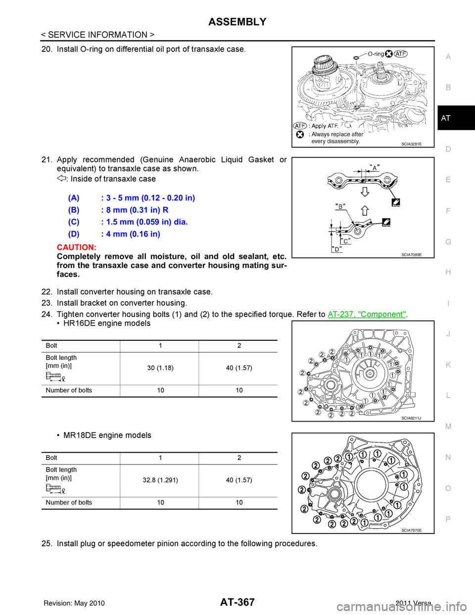
20. Install O-ring on differential oil port of transaxle case.
21. Apply recommended (Genuine Anaerobic Liquid Gasket or equivalent) to transaxle case as shown.
: Inside of transaxle case
CAUTION:
Completely remove all moisture, oil and old sealant, etc.
from the transaxle case and converter housing mating sur-
faces.
22. Install converter housing on transaxle case.
23. Install bracket on converter housing.
24. Tighten converter housing bolts (1) and (2) to the specified torque. Refer to AT-237, "
Component".
• HR16DE engine models
• MR18DE engine models
25. Install plug or speedometer pinion according to the following procedures.
SCIA3281E
(A) : 3 - 5 mm (0.12 - 0.20 in)
(B) : 8 mm (0.31 in) R
(C) : 1.5 mm (0.059 in) dia.
(D) : 4 mm (0.16 in)
SCIA7089E
Bolt 12
Bolt length
[mm (in)] 30 (1.18)40 (1.57)
Number of bolts 1010
SCIA6211J
Bolt 12
Bolt length
[mm (in)] 32.8 (1.291)40 (1.57)
Number of bolts 1010
SCIA7970E
Revision: May 2010 2011 Versa
Page 387 of 3787

AT-370
< SERVICE INFORMATION >
ASSEMBLY
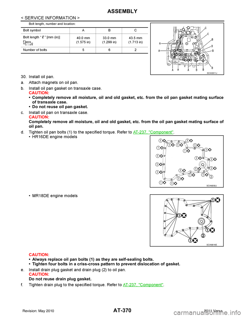
Bolt length, number and location:
30. Install oil pan.
a. Attach magnets on oil pan.
b. Install oil pan gasket on transaxle case.CAUTION:
• Completely remove all moisture, oil and old gasket , etc. from the oil pan gasket mating surface
of transaxle case.
• Do not reuse oil pan gasket.
c. Install oil pan on transaxle case. CAUTION:
Completely remove all moisture, oil and old gasket , etc. from the oil pan gasket mating surface of
oil pan.
d. Tighten oil pan bolts (1) to the specified torque. Refer to AT-237, "
Component".
• HR16DE engine models
• MR18DE engine models
CAUTION:
• Always replace oil pan bolts (1) as they are self-sealing bolts.
• Tighten four bolts in a criss-cross pattern to prevent dislocation of gasket.
e. Install drain plug gasket and drain plug (2) to oil pan. CAUTION:
Do not reuse drain plug gasket.
f. Tighten drain plug to the specified torque. Refer to AT-237, "
Component".
Bolt symbolABC
Bolt length “ ” [mm (in)] 40.0 mm
(1.575 in) 33.0 mm
(1.299 in) 43.5 mm
(1.713 in)
Number of bolts 562
SCIA5911J
SCIA6050J
SCIA8016E
Revision: May 2010 2011 Versa
Page 393 of 3787

AT-376
< SERVICE INFORMATION >
SERVICE DATA AND SPECIFICATIONS (SDS)
Unit: mm (in)
AccumulatorINFOID:0000000005928316
RETURN SPRINGS
Unit: mm (in)
Unit: mm (in)
O-RINGS
Unit: mm (in)
Clutches and BrakesINFOID:0000000005928317
REVERSE CLUTCH
Locationspring designation Free length (l) Outer diameter (D)
Upper body L14 Pilot valve spring
38.98 (1.5346)8.9 (0.350)
L15 1–2 accumulator valve spring
20.5 (0.807)6.95 (0.2736)
1–2 accumulator piston spring 55.66 (2.1913)19.5 (0.768)
L16 1st reducing valve spring 27.0 (1.063)7.0 (0.276)
L17 3–2 timing valve spring 23.0 (0.906)6.65 (0.2618)
L18 Overrun clutch reducing valve spring37.5 (1.476)7.0 (0.276)
L19 Torque converter relief valve spring 33.3 (1.311)9.0 (0.354)
L20 Torque converter clutch control valve spring 53.01 (2.0870)6.5 (0.256)
L21 Cooler check valve spring 28.04 (1.1039)7.15 (0.2815)
Lower body L3 Pressure regulator valve spring
45.0 (1.772)15.0 (0.591)
L4 Overrun clutch control valve spring 21.7 (0.854)7.0 (0.276)
L5 Accumulator control valve spring 22.0 (0.866)6.5 (0.256)
L6 Shift valve A spring 21.7 (0.854)7.0 (0.276)
L7 Shuttle valve spring 51.0 (2.008)5.65 (0.2224)
L12 Shift valve B spring 21.7 (0.854)7.0 (0.276)
L13 Pressure modifier valve spring
32.0 (1.260)6.9 (0.272)
Pressure modifier piston spring 30.5 (1.201)9.8 (0.386)
— Line pressure relief valve spring 17.02 (0.6701)8.0 (0.315)
— Torque converter pressure holding spring 9.0 (0.354)7.3 (0.287)
Location Free length (L1)
Servo release accumulator 62.8 (2.472)
LocationLength (L2)
N-D accumulator 46.5 (1.831)
LocationInner diameter (Small) Inner diameter (Large)
Servo release accumulator 26.9 (1.059)44.2 (1.740)
N-D accumulator 34.6 (1.362)39.4 (1.551)
Number of drive plates 2
Number of driven plates 2
Drive plate thickness [mm (in)] Standard
2.0 (0.079)
Allowable limit 1.8 (0.071)
Driven plate thickness [mm (in)] Standard 2.0 (0.079)
Clearance [mm (in)] Standard
0.5 - 0.8 (0.020 - 0.031)
Allowable limit 1.2 (0.047)
Revision: May 2010 2011 Versa
Page 396 of 3787

SERVICE DATA AND SPECIFICATIONS (SDS)AT-379
< SERVICE INFORMATION >
DE
F
G H
I
J
K L
M A
B
AT
N
O P
Unit: mm (in)
Output ShaftINFOID:0000000005928324
SEAL RING CLEARANCE
SEAL RING
Unit: mm (in)
TURNING TORQUE (FOR HR16DE ENGINE MODELS)
END PLAY (FOR MR18DE ENGINE MODELS)
Bearing RetainerINFOID:0000000005928325
SEAL RING CLEARANCE
Total End PlayINFOID:0000000005928326
Reverse Clutch End PlayINFOID:0000000005928327
Removal and InstallationINFOID:0000000005928328
Shift Solenoid ValvesINFOID:0000000005928329
Return spring Free length
2nd servo return sp ring 32.5 (1.280)
OD servo return sp ring 38.52 (1.5165)
Output shaft seal ring clearance [mm (in)]Standard 0.10 - 0.25 (0.0039 - 0.0098)
Allowable limit
0.25 (0.0098)
Outer diameter Inner diameter Width
29.5 (1.161) 26.2 (1.031)1.95 (0.0768)
Turning torque of output shaft ·m (kg-m, in-lb) 0.25 - 0.88 (0.03 - 0.08, 3 - 7)
Output shaft end play mm (in) 0 - 0.5 (0 - 0.020)
Bearing retainer seal ring clearance [mm (in)]Standard 0.10 - 0.27 (0.0039 - 0.0106)
Allowable limit
0.27 (0.0106)
Total end play [mm (in)] 0.25 - 0.55 (0.0098 - 0.0217)
Reverse clutch end play [mm (in)] 0.65 - 1.0 (0.0256 - 0.039)
Engine HR16DE MR18DE
Distance between end of converter housing and torque converter [mm (in)] 16.2 (0.638)14.4 (0.567)
Gear position 1234
Shift solenoid valve A ON (Closed)OFF (Open)OFF (Open)ON (Closed)
Shift solenoid valve B ON (Closed)ON (Closed) OFF (Open)OFF (Open)
Revision: May 2010 2011 Versa