2011 NISSAN LATIO key battery
[x] Cancel search: key batteryPage 604 of 3787

BL-94
< SERVICE INFORMATION >
INTELLIGENT KEY SYSTEM
List of Operation Related Parts
Parts marked with × are the parts related to operation.
OFF position warn-
ing chime For internal• Ignition switch is turned from ACC to
OFF.
[ignition switch is pressed (ignition knob
switch is ON).]
• Ignition switch is in the LOCK position and pressed for 1 second. activate — — Flash —
For external When driver door is opened and then
closed while the OFF position warning
chime above is operating —activate—— —
Ta k e a w a y w a r n i n g Right after
door is closed
Right after door is closed and the following
conditions are met.
• Ignition knob is pressed and in rotatable
or rotated state
• Intelligent Key can not be detected in-
side the vehicle —activate
Flash
(red) ——
Any door is
opened Any door is opened and the following con-
ditions are met.
• Ignition knob is pressed and in rotatable
or rotated state
• Intelligent Key unit will perform key ID verification with Intelligent Key through
inside key antenna every 5 second, if
the key ID verification is NG. ——
Flash
(red) ——
Ta k e a w a y
from the win-
dow Take away from the window and the fol-
lowing conditions are met.
• Ignition knob is pressed and in rotatable
or rotated state
• Vehicle speed below 5 km/h (3 m.p.h.)
• Intelligent Key unit will perform key ID
verification with Intelligent Key through
inside key antenna every 30 second, if
the key ID verification is NG.
(This warning function will be disabled if
mechanical key is inserted into the key
cylinder.)
NOTE:
Default setting of this function is OFF. activate —
Flash
(red) ——
Door lock opera-
tion warning Lock opera-
tion with re-
quest switchLock operation with request switch and
the following condition is met.
• Intelligent Key is inside the vehicle
—activate—— —
Intelligent Key low battery warning When Intelligent Key is low battery, Intelli-
gent Key unit is detected after ignition
switch is turned ON.
——
Flash
(green) ——
Operation
ConditionWarning chime/buzzer Warning lamp
Chime
(combina-
tion meter) Buzzer(s) KEY
LOCK
(M/T) P-SHIFT
(CVT or
A/T)
Revision: May 2010 2011 Versa
Page 605 of 3787

INTELLIGENT KEY SYSTEMBL-95
< SERVICE INFORMATION >
C
DE
F
G H
J
K L
M A
B
BL
N
O P
CHANGE SETTINGS FUNCTION
The settings for each function c an be changed with the CONSULT-III.
Changing Settings Using CONSULT-III
The settings for the Intelligent Key system func tions can be changed using CONSULT-III (WORK SUPPORT).
Refer to BL-117, "
CONSULT-III Application Item".
NOTE:
Once a function setting is changed, it will remain effective even if the battery is disconnected.
INTELLIGENT KEY REGISTRATION
Intelligent Key-ID registration is performed using the CONSULT-III.
CAUTION:
• After a new Intelligent Key-ID is registered, be sure to check the function.
• When registering an additional Intelligent Key-ID , take any Intelligent Keys already registered and
Intelligent Keys for any other vehicles out of the vehicle before starting.
CONSULT-III can be used to check and delete Intelligent Key-IDs.
For further information, see the CONS ULT-III Operation Manual NATS.
STEERING LOCK SOLENOID REGISTRATION
Steering Lock Solenoid ID Registration
CAUTION:
• The method for registering a steering lock solenoid ID depends on the status of the steering lock
solenoid and Intelligent Key unit (new or old unit).
• After registration is completed, press ignition switch with an Intelligent Key in the vehicle so that it can be turned, and confirm that it cannot be turned even when ignition sw itch is pressed without an
Intelligent Key in the vehicle.
For further information, see the CONSULT-III Operation Manual NATS-IVIS/NVIS.
CAN Communication System DescriptionINFOID:0000000005929329
Refer to LAN-7.
Warning and alarm functions
Intelligent Key
Key switch
Ignition knob switch
Ignition switch ACC position input signal
Ignition switch ON position input signal
Door switch
Door request switch
Inside key antenna
Outside key antenna (Driver, Passenger)
Outside key antenna (rear bumper)
Intelligent Key warning buzzer(s)
Intelligent Key unit
CAN communication system
BCM
Warning lamp
Warning chime (combination meter)
Ignition switch warning chime × ××××× ×
Ignition key warning chime
(When mechanical key used) ×××
×××
OFF position warning chime For internal
××× ××××××
For external ×××× ×××××
Take away warning chime Right after door is
closed
××× × × ×××××
Any door is open ××× × × ××××
Take away from
window ××× × × ××××××
Door lock operation warning chime ×××××××××
Intelligent Key low battery warning ×××× ××
Revision: May 2010 2011 Versa
Page 618 of 3787
BL-108
< SERVICE INFORMATION >
INTELLIGENT KEY SYSTEM
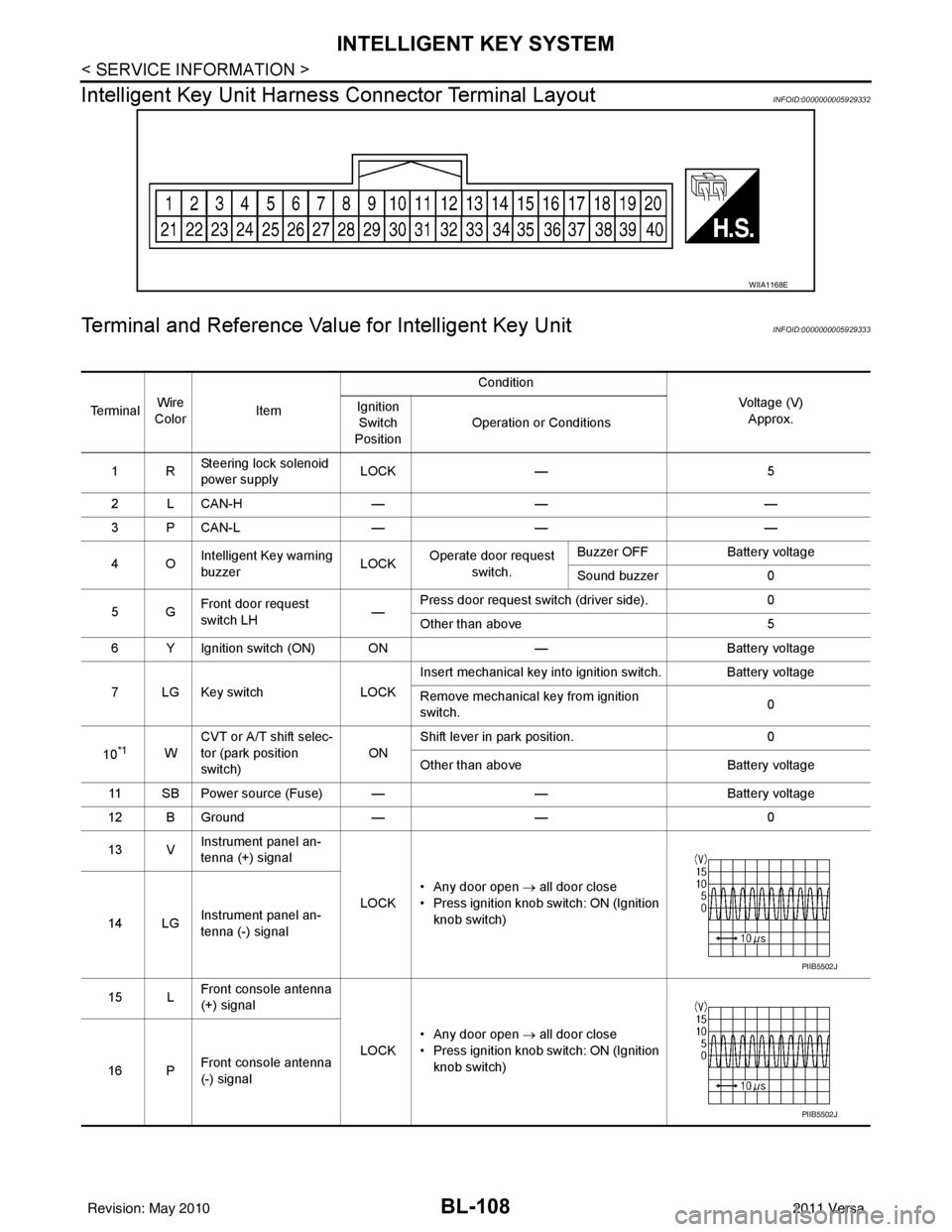
Intelligent Key Unit Harnes s Connector Terminal Layout
INFOID:0000000005929332
Terminal and Reference Value for Intelligent Key UnitINFOID:0000000005929333
WIIA1168E
Te r m i n a lWire
Color Item Condition
Voltage (V)Approx.
Ignition
Switch
Position Operation or Conditions
1R Steering lock solenoid
power supply LOCK
— 5
2 L CAN-H —— —
3 P CAN-L —— —
4O Intelligent Key warning
buzzer LOCK
Operate door request
switch. Buzzer OFF
Battery voltage
Sound buzzer 0
5G Front door request
switch LH —Press door request switch (driver side).
0
Other than above 5
6 Y Ignition switch (ON) ON —Battery voltage
7 LG Key switch LOCKInsert mechanical key into ignition switch. Battery voltage
Remove mechanical key from ignition
switch.
0
10
*1W CVT or A/T shift selec-
tor (park position
switch)
ONShift lever in park position.
0
Other than above Battery voltage
11 SB Power source (Fuse) — —Battery voltage
12 B Ground —— 0
13 V Instrument panel an-
tenna (+) signal
LOCK• Any door open
→ all door close
• Press ignition knob switch: ON (Ignition knob switch)
14 LG Instrument panel an-
tenna (-) signal
15 L Front console antenna
(+) signal
LOCK• Any door open
→ all door close
• Press ignition knob switch: ON (Ignition knob switch)
16 P Front console antenna
(-) signal
PIIB5502J
PIIB5502J
Revision: May 2010
2011 Versa
Page 619 of 3787

INTELLIGENT KEY SYSTEMBL-109
< SERVICE INFORMATION >
C
DE
F
G H
J
K L
M A
B
BL
N
O P
17 W Rear bumper antenna
(+) signal
LOCK Press back door request switch.
18 B Rear bumper antenna
(-) signal
19 V Front outside antenna
LH (+) signal
LOCK Press door request switch LH.
20 P Front outside antenna
LH (-) signal
22
*2BR Key interlock solenoid — With Intelligent Key present or mechanical
key in ignition cylinder, press "PUSH" but-
ton on ignition cylinder.
Battery voltage
Other than above 0
23 LG Back door open output — Back door open (switch closed)
0
Back door closed (switch open) 5
24 V Back door opener
switch —Press and hold back door switch.
0
Other than above 5
25 L Front door request
switch RH —Press front door request switch RH.
0
Other than above 5
26 SB Stop lamp switch —Depress brake pedal
Battery voltage
Other than above 0
27 W Ignition knob switch — Press ignition switch.
Battery voltage
Release ignition switch. 0
28 Y Unlock sensor
(driver side) —Door (driver si
de) is locked. 5
Door (driver side ) is unlocked. 0
29 V Back door request
switch (hatchback)
—Press back door request switch.
0
Other than above 5
Trunk opener request
switch (sedan) —Press trunk opener request switch.
0
Other than above 5
31 BR Steering lock solenoid
ground
——
0
32 GR Steering lock solenoid
communication signal LOCKWhen Intelligent Key is inside vehicle,
press ignition knob switch.
Other than above
5
Terminal
Wire
Color Item Condition
Voltage (V)Approx.
Ignition
Switch
Position Operation or Conditions
SIIA1910J
SIIA1910J
SIIA1911J
Revision: May 2010
2011 Versa
Page 620 of 3787
BL-110
< SERVICE INFORMATION >
INTELLIGENT KEY SYSTEM
*1: With continuously variable transmission (CVT) or automatic transmission (A/T).
*2: With manual transmission (M/T).
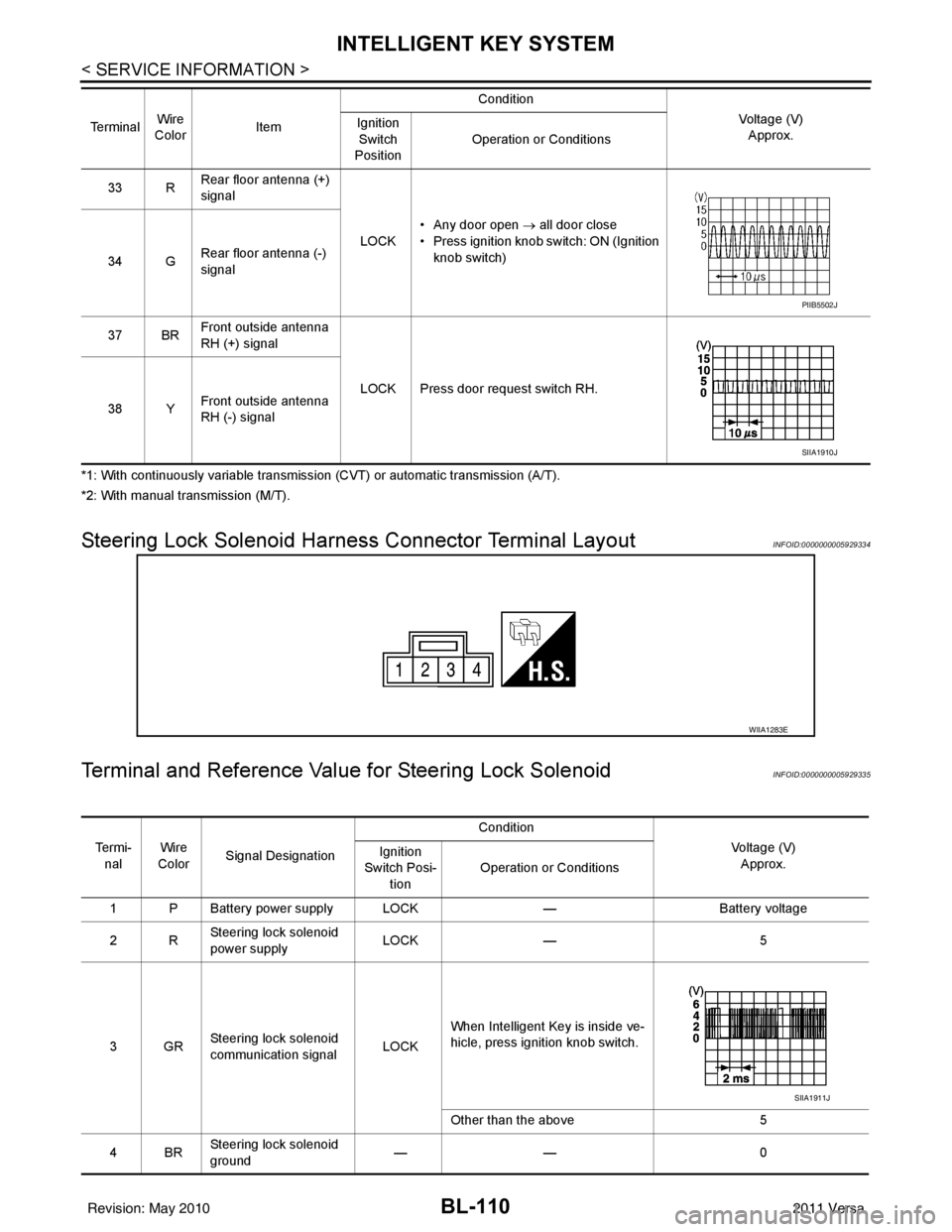
Steering Lock Solenoid Harn ess Connector Terminal LayoutINFOID:0000000005929334
Terminal and Reference Valu e for Steering Lock SolenoidINFOID:0000000005929335
33 RRear floor antenna (+)
signal
LOCK• Any door open
→ all door close
• Press ignition knob switch: ON (Ignition knob switch)
34 G Rear floor antenna (-)
signal
37 BR Front outside antenna
RH (+) signal
LOCK Press door request switch RH.
38 Y Front outside antenna
RH (-) signal
Te r m i n a l
Wire
Color Item Condition
Voltage (V)Approx.
Ignition
Switch
Position Operation or Conditions
PIIB5502J
SIIA1910J
WIIA1283E
Te r m i -
nal Wire
Color Signal Designation Condition
Voltage (V)Approx.
Ignition
Switch Posi- tion Operation or Conditions
1 P Battery power supply LOCK —Battery voltage
2R Steering lock solenoid
power supply LOCK
— 5
3GR Steering lock solenoid
communication signal
LOCKWhen Intelligent Key is inside ve-
hicle, press ignition knob switch.
Other than the above
5
4BR Steering lock solenoid
ground ——
0
SIIA1911J
Revision: May 2010 2011 Versa
Page 621 of 3787
INTELLIGENT KEY SYSTEMBL-111
< SERVICE INFORMATION >
C
DE
F
G H
J
K L
M A
B
BL
N
O P
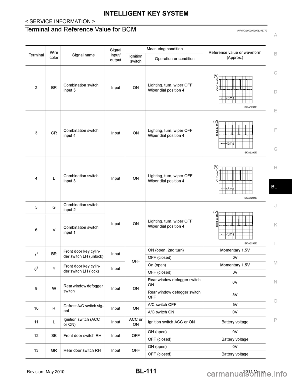
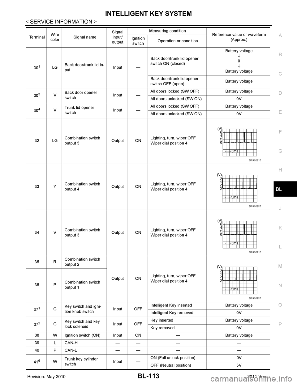
Terminal and Reference Value for BCMINFOID:0000000006215772
Te r m i n a l Wire
color Signal name Signal
input/
output Measuring condition
Reference value or waveform
(Approx.)
Ignition
switch Operation or condition
2BR Combination switch
input 5
Input ONLighting, turn, wiper OFF
Wiper dial position 4
3GR Combination switch
input 4 Input ONLighting, turn, wiper OFF
Wiper dial position 4
4L Combination switch
input 3
Input ONLighting, turn, wiper OFF
Wiper dial position 4
5G Combination switch
input 2
Input ONLighting, turn, wiper OFF
Wiper dial position 4
6V Combination switch
input 1
7
7BR Front door key cylin-
der switch LH (unlock) Input
OFFON (open, 2nd turn)
Momentary 1.5V
OFF (closed) 0V
8
7Y Front door key cylin-
der switch LH (lock) InputOn (open)
Momentary 1.5V
OFF (closed) 0V
9W Rear window defogger
switch Input ONRear window defogger switch
ON
0V
Rear window defogger switch
OFF 5V
10 R Defrost A/C switch sig-
nal
Input ONA/C switch OFF
5V
A/C switch ON 0V
11 L Ignition switch (ACC
or ON) InputACC or
ON Ignition switch ACC or ON
Battery voltage
12 SB Front door switch RH Input OFF ON (open)
0V
OFF (closed) Battery voltage
13 GR Rear door switch RH Input OFF ON (open)
0V
OFF (closed) Battery voltage
SKIA5291E
SKIA5292E
SKIA5291E
SKIA5292E
Revision: May 2010 2011 Versa
Page 622 of 3787
BL-112
< SERVICE INFORMATION >
INTELLIGENT KEY SYSTEM
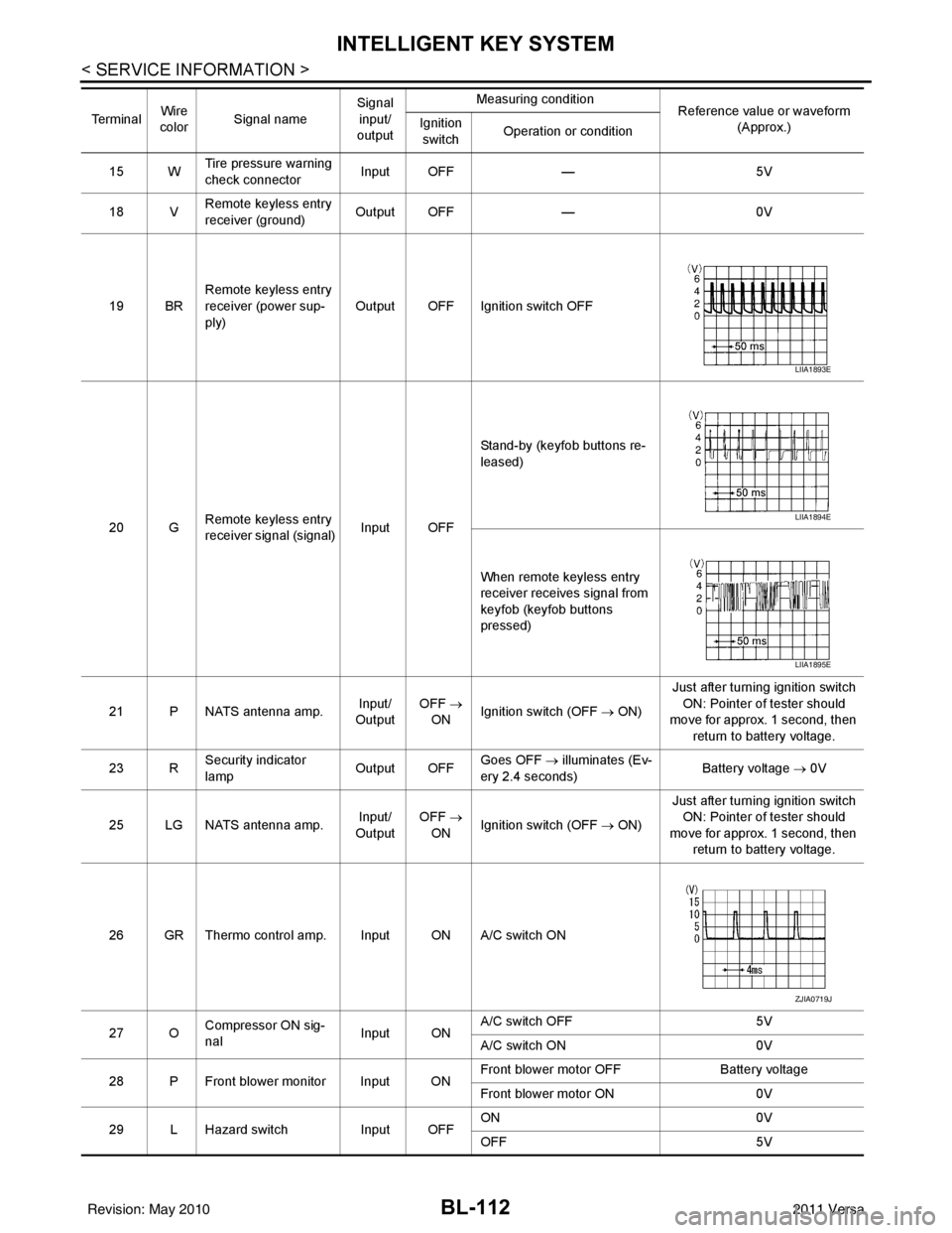
15 WTire pressure warning
check connector
Input OFF
—5V
18 V Remote keyless entry
receiver (ground) Output OFF
—0V
19 BR Remote keyless entry
receiver (power sup-
ply) Output OFF Ignition switch OFF
20 G Remote keyless entry
receiver signal (signal)
Input OFFStand-by (keyfob buttons re-
leased)
When remote keyless entry
receiver receives signal from
keyfob (keyfob buttons
pressed)
21 P NATS antenna amp. Input/
Output OFF
→
ON Ignition switch (OFF
→ ON)Just after turning ignition switch
ON: Pointer of tester should
move for approx. 1 second, then
return to battery voltage.
23 R Security indicator
lamp Output OFF
Goes OFF
→ illuminates (Ev-
ery 2.4 seconds) Battery voltage
→ 0V
25 LG NATS antenna amp. Input/
Output OFF
→
ON Ignition switch (OFF
→ ON)Just after turning ignition switch
ON: Pointer of tester should
move for approx. 1 second, then return to battery voltage.
26 GR Thermo control amp. Input ON A/C switch ON
27 O Compressor ON sig-
nal Input ONA/C switch OFF
5V
A/C switch ON 0V
28 P Front blower monitor Input ON Front blower motor OFF
Battery voltage
Front blower motor ON 0V
29 L Hazard switch Input OFFON
0V
OFF 5V
Te r m i n a l
Wire
color Signal name Signal
input/
output Measuring condition
Reference value or waveform
(Approx.)
Ignition
switch Operation or condition
LIIA1893E
LIIA1894E
LIIA1895E
ZJIA0719J
Revision: May 2010
2011 Versa
Page 623 of 3787
INTELLIGENT KEY SYSTEMBL-113
< SERVICE INFORMATION >
C
DE
F
G H
J
K L
M A
B
BL
N
O P
301LG Back door/trunk lid in-
put Input —Back door/trunk lid opener
switch ON (closed) Battery voltage
↓0
↓
Battery voltage
Back door/trunk lid opener
switch OFF (open) Battery voltage
30
3V Back door opener
switch
Input —All doors locked (SW OFF)
Battery voltage
All doors unlocked (SW ON) 0V
30
4V Trunk lid opener
switch
Input —All doors locked (SW OFF)
Battery voltage
All doors unlocked (SW ON) 0V
32 LG Combination switch
output 5 Output ONLighting, turn, wiper OFF
Wiper dial position 4
33 Y Combination switch
output 4 Output ON
Lighting, turn, wiper OFF
Wiper dial position 4
34 V Combination switch
output 3
Output ONLighting, turn, wiper OFF
Wiper dial position 4
35 R Combination switch
output 2
Output ONLighting, turn, wiper OFF
Wiper dial position 4
36 P Combination switch
output 1
37
1G Key switch and igni-
tion knob switch Input OFFIntelligent Key inserted
Battery voltage
Intelligent Key removed 0V
37
2G Key switch and key
lock solenoid Input OFFKey inserted
Battery voltage
Key removed 0V
38 W Ignition switch (ON) Input ON —Battery voltage
39 L CAN-H — —— —
40 P CAN-L — —— —
41
6W Trunk key cylinder
switch
Input —ON (Full unlock position)
0V
OFF (Neutral position) 5V
Te r m i n a l
Wire
color Signal name Signal
input/
output Measuring condition
Reference value or waveform
(Approx.)
Ignition
switch Operation or condition
SKIA5291E
SKIA5292E
SKIA5291E
SKIA5292E
Revision: May 2010
2011 Versa