2011 NISSAN LATIO key battery
[x] Cancel search: key batteryPage 584 of 3787
BL-74
< SERVICE INFORMATION >
REMOTE KEYLESS ENTRY SYSTEM
ACC Switch Circuit Check
INFOID:0000000005929314
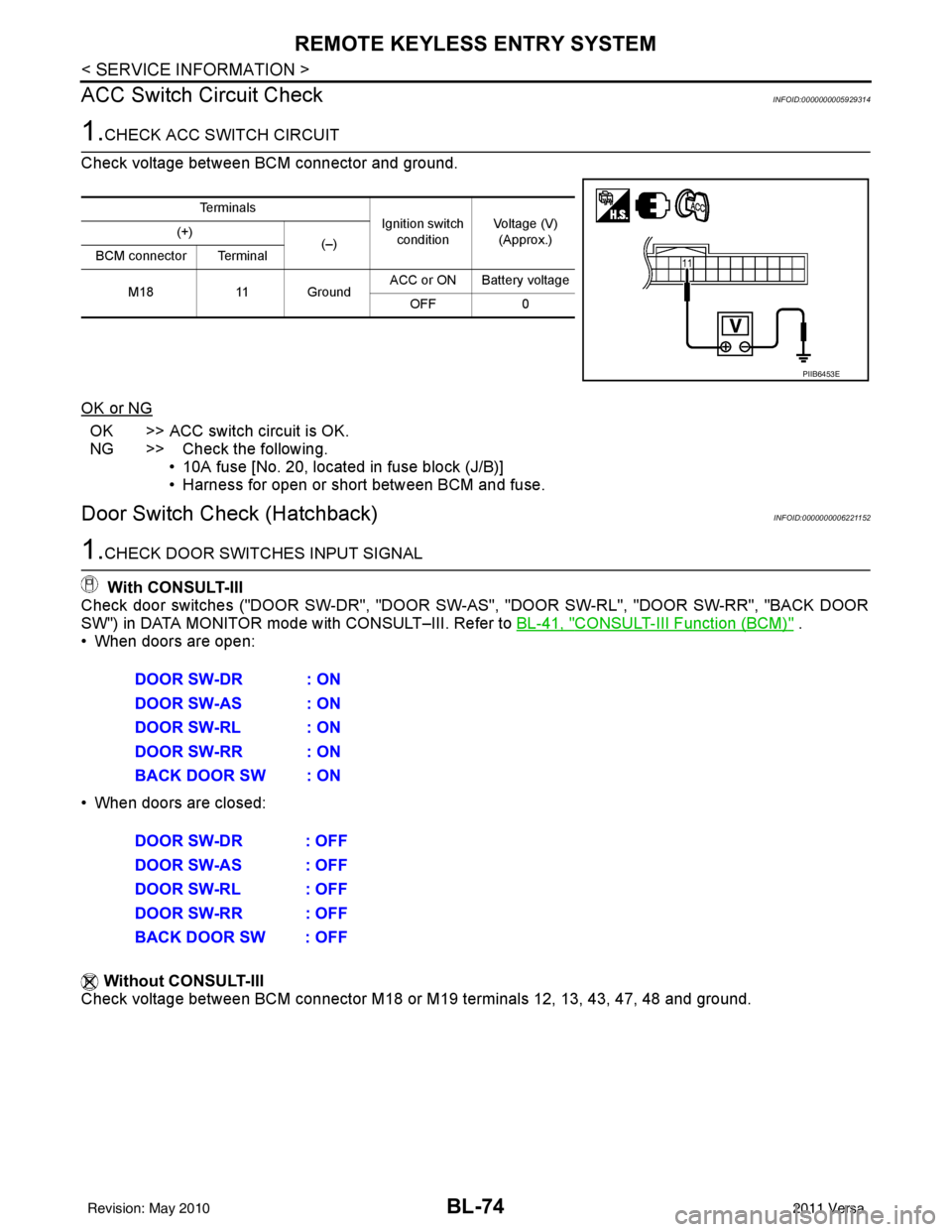
1.CHECK ACC SWITCH CIRCUIT
Check voltage between BCM connector and ground.
OK or NG
OK >> ACC switch circuit is OK.
NG >> Check the following. • 10A fuse [No. 20, located in fuse block (J/B)]
• Harness for open or short between BCM and fuse.
Door Switch Check (Hatchback)INFOID:0000000006221152
1.CHECK DOOR SWITCHES INPUT SIGNAL
With CONSULT-III
Check door switches ("DOOR SW-DR", "DOOR SW-AS", "DOOR SW-RL", "DOOR SW-RR", "BACK DOOR
SW") in DATA MONITOR mode with CONSULT–III. Refer to BL-41, "
CONSULT-III Function (BCM)" .
• When doors are open:
• When doors are closed:
Without CONSULT-III
Check voltage between BCM connector M18 or M19 terminals 12, 13, 43, 47, 48 and ground.
Te r m i n a l s
Ignition switch
condition Voltage (V)
(Approx.)
(+)
(–)
BCM connector Terminal
M18 11 Ground ACC or ON Battery voltage
OFF 0
PIIB6453E
DOOR SW-DR : ON
DOOR SW-AS : ON
DOOR SW-RL : ON
DOOR SW-RR : ON
BACK DOOR SW : ON
DOOR SW-DR : OFF
DOOR SW-AS : OFF
DOOR SW-RL : OFF
DOOR SW-RR : OFF
BACK DOOR SW : OFF
Revision: May 2010 2011 Versa
Page 585 of 3787
REMOTE KEYLESS ENTRY SYSTEMBL-75
< SERVICE INFORMATION >
C
DE
F
G H
J
K L
M A
B
BL
N
O P
OK or NG
OK >> Door switch circuit is OK.
NG >> GO TO 2
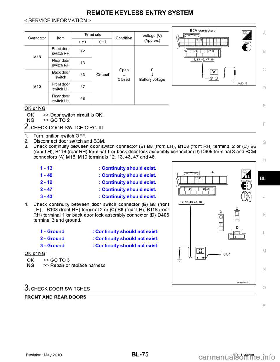
2.CHECK DOOR SWITCH CIRCUIT
1. Turn ignition switch OFF.
2. Disconnect door switch and BCM.
3. Check continuity between door switch connector (B) B8 (front LH), B108 (front RH) terminal 2 or (C) B6
(rear LH), B116 (rear RH) terminal 1 or back door lock assembly connector (D) D405 terminal 3 and BCM
connectors (A) M18, M19 te rminals 12, 13, 43, 47 and 48.
4. Check continuity between door switch connector (B) B8 (front LH), B108 (front RH) terminal 2 or (C) B6 (rear LH), B116 (rear
RH) terminal 1 or back door lo ck assembly connector (D) D405
terminal 3 and ground.
OK or NG
OK >> GO TO 3
NG >> Repair or replace harness.
3.CHECK DOOR SWITCHES
FRONT AND REAR DOORS
Connector Item Te r m i n a l s
ConditionVoltage (V)
(Approx.)
( + ) ( – )
M18 Front door
switch RH 12
Ground Open
↓
Closed 0
↓
Battery voltage
Rear door
switch RH 13
M19 Back door
switch 43
Front door switch LH 47
Rear door switch LH 48
LIIA1041E
1 - 13
: Continuity should exist.
1 - 48 : Continuity should exist.
2 - 12 : Continuity should exist.
2 - 47 : Continuity should exist.
3 - 43 : Continuity should exist.
1 - Ground : Continuity should not exist.
2 - Ground : Continuity should not exist.
3 - Ground : Continuity should not exist.
WIIA1244E
Revision: May 2010 2011 Versa
Page 587 of 3787
REMOTE KEYLESS ENTRY SYSTEMBL-77
< SERVICE INFORMATION >
C
DE
F
G H
J
K L
M A
B
BL
N
O P
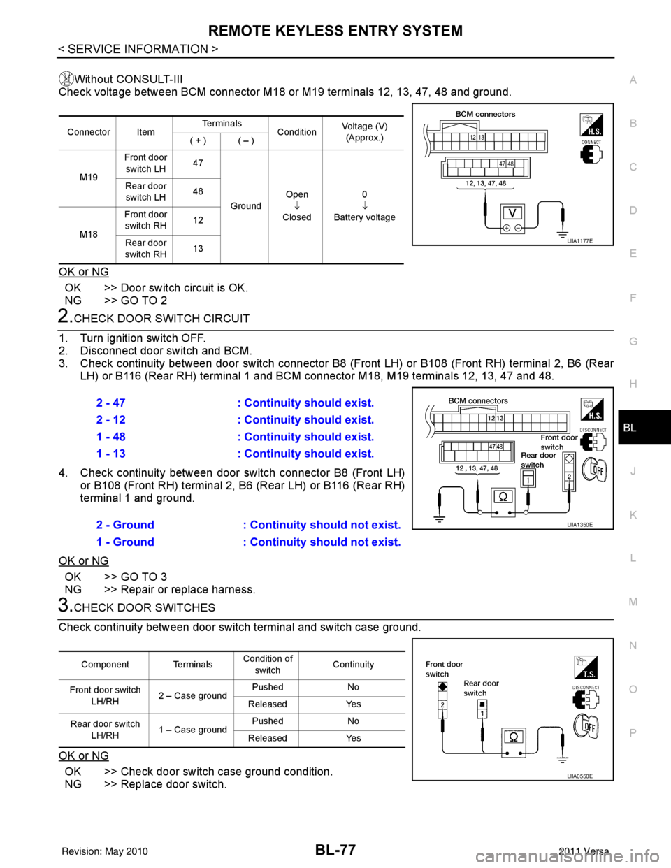
Without CONSULT-III
Check voltage between BCM connector M18 or M19 terminals 12, 13, 47, 48 and ground.
OK or NG
OK >> Door switch circuit is OK.
NG >> GO TO 2
2.CHECK DOOR SWITCH CIRCUIT
1. Turn ignition switch OFF.
2. Disconnect door switch and BCM.
3. Check continuity between door switch connector B8 (F ront LH) or B108 (Front RH) terminal 2, B6 (Rear
LH) or B116 (Rear RH) terminal 1 and BCM connector M18, M19 terminals 12, 13, 47 and 48.
4. Check continuity between door switch connector B8 (Front LH) or B108 (Front RH) terminal 2, B6 (Rear LH) or B116 (Rear RH)
terminal 1 and ground.
OK or NG
OK >> GO TO 3
NG >> Repair or replace harness.
3.CHECK DOOR SWITCHES
Check continuity between door switch terminal and switch case ground.
OK or NG
OK >> Check door switch case ground condition.
NG >> Replace door switch.
Connector Item Te r m i n a l s
ConditionVoltage (V)
(Approx.)
( + ) ( – )
M19 Front door
switch LH 47
Ground Open
↓
Closed 0
↓
Battery voltage
Rear door
switch LH 48
M18 Front door
switch RH 12
Rear door
switch RH 13
LIIA1177E
2 - 47
: Continuity should exist.
2 - 12 : Continuity should exist.
1 - 48 : Continuity should exist.
1 - 13 : Continuity should exist.
2 - Ground : Continuity should not exist.
1 - Ground : Continuity should not exist.
LIIA1350E
Component Terminals Condition of
switch Continuity
Front door switch LH/RH 2 – Case ground Pushed
No
Released Yes
Rear door switch LH/RH 1 – Case ground Pushed
No
Released Yes
LIIA0550E
Revision: May 2010 2011 Versa
Page 588 of 3787
BL-78
< SERVICE INFORMATION >
REMOTE KEYLESS ENTRY SYSTEM
Key Switch (I nsert) Check
INFOID:0000000006221154
1.CHECK KEY SWITCH INPUT SIGNAL
With CONSULT-III
Check key switch "KEY ON SW" in DATA MONITOR mode with CONSULT–III. Refer to BL-41, "
CONSULT-III
Function (BCM)" .
• When key is inserted into ignition key cylinder:
• When key is removed from ignition key cylinder:
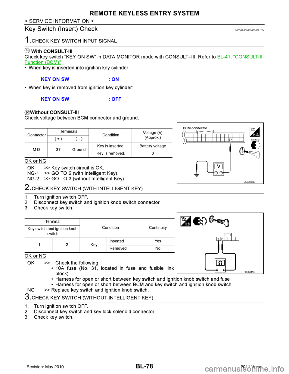
Without CONSULT-III
Check voltage between BCM connector and ground.
OK or NG
OK >> Key switch circuit is OK.
NG-1 >> GO TO 2 (with Intelligent Key).
NG-2 >> GO TO 3 (without Intelligent Key).
2.CHECK KEY SWITCH (WITH INTELLIGENT KEY)
1. Turn ignition switch OFF.
2. Disconnect key switch and ignition knob switch connector.
3. Check key switch.
OK or NG
OK >> Check the following. • 10A fuse (No. 31, located in fuse and fusible link
block)
• Harness for open or short between key switch and ignition knob switch and fuse
• Harness for open or short between BCM and key switch and ignition knob switch
NG >> Replace key switch and ignition knob switch.
3.CHECK KEY SWITCH (WITHO UT INTELLIGENT KEY)
1. Turn ignition switch OFF.
2. Disconnect key switch and key lock solenoid connector.
3. Check key switch. KEY ON SW
: ON
KEY ON SW : OFF
ConnectorTe r m i n a l s
ConditionVoltage (V)
(Approx.)
( + ) ( – )
M18 37 Ground Key is inserted. Battery voltage
Key is removed. 0
LIIA0567E
Te r m i n a l
Condition Continuity
Key switch and ignition knob
switch
12K ey Inserted
Yes
Removed No
PIIB6411E
Revision: May 2010 2011 Versa
Page 589 of 3787
![NISSAN LATIO 2011 Service Repair Manual REMOTE KEYLESS ENTRY SYSTEMBL-79
< SERVICE INFORMATION >
C
DE
F
G H
J
K L
M A
B
BL
N
O P
OK or NG
OK >> Check the following. • 10A fuse [No. 14, located in fuse block (J/B)]
• Harness for open or NISSAN LATIO 2011 Service Repair Manual REMOTE KEYLESS ENTRY SYSTEMBL-79
< SERVICE INFORMATION >
C
DE
F
G H
J
K L
M A
B
BL
N
O P
OK or NG
OK >> Check the following. • 10A fuse [No. 14, located in fuse block (J/B)]
• Harness for open or](/manual-img/5/57357/w960_57357-588.png)
REMOTE KEYLESS ENTRY SYSTEMBL-79
< SERVICE INFORMATION >
C
DE
F
G H
J
K L
M A
B
BL
N
O P
OK or NG
OK >> Check the following. • 10A fuse [No. 14, located in fuse block (J/B)]
• Harness for open or short between key switch and keylock solenoid and fuse
• Harness for open or short between BCM and key
switch and key lock solenoid
NG >> Replace key switch and key lock solenoid.
Hazard Function CheckINFOID:0000000005929318
1.CHECK HAZARD WARNING LAMP
Does hazard warning lamp flash with hazard switch?
OK or NG
OK >> Hazard warning lamp circuit is OK.
NG >> Check hazard circuit. Refer to LT- 5 0
.
Horn Function CheckINFOID:0000000005929319
First perform the “SELF-DIAG RESULTS” in “BCM” with CONSULT-III, then perform the trouble diagnosis of
malfunction system indicated “SELF-DIAG RESULTS” of “BCM”. Refer to BCS-18, "
CAN Communication
Inspection Using CONSULT-III (Self-Diagnosis)" .
1.CHECK HORN FUNCTION
Does horn sound with horn switch?
OK or NG
OK >> GO TO 2
NG >> Check horn circuit. Refer to WW-40
.
2.CHECK IPDM E/R INPUT SIGNAL
Check voltage between IPDM E/R connector and ground.
OK or NG
OK >> Replace IPDM E/R. Refer to PG-28, "Removal and
Installation of IPDM E/R".
NG >> GO TO 3
3.CHECK HORN RELAY CIRCUIT
1. Turn ignition switch OFF.
2. Disconnect IPDM E/R and horn relay connector.
Terminals Condition Continuity
1 – 2 Key is inserted.
Yes
Key is removed. No
PIIB6411E
Te r m i n a l s
Voltage (V)
(Approx.)
(+)
(–)
IPDM E/R connector Terminal
E46 45Ground Battery voltage
WIIA1251E
Revision: May 2010 2011 Versa
Page 595 of 3787
REMOTE KEYLESS ENTRY SYSTEMBL-85
< SERVICE INFORMATION >
C
DE
F
G H
J
K L
M A
B
BL
N
O P
• When registering an additional keyfob, the existing ID codes in memory may or may not be erased. If five ID
codes are stored in memory, when an additional code is registered, only the oldest code is erased. If less
than five ID codes are stored in memory, when an additional ID code is registered, the new ID code is added
and no ID codes are erased.
• If you need to activate more than two additional new keyfobs, repeat the procedure “Additional ID code
entry” for each new keyfob.
• Entry of maximum five ID codes is allowed. When mo re than five ID codes are entered, the oldest ID code
will be erased.
• Even if same ID code that is already in the memory is input, the same ID code can be entered. The code is
counted as an additional code.
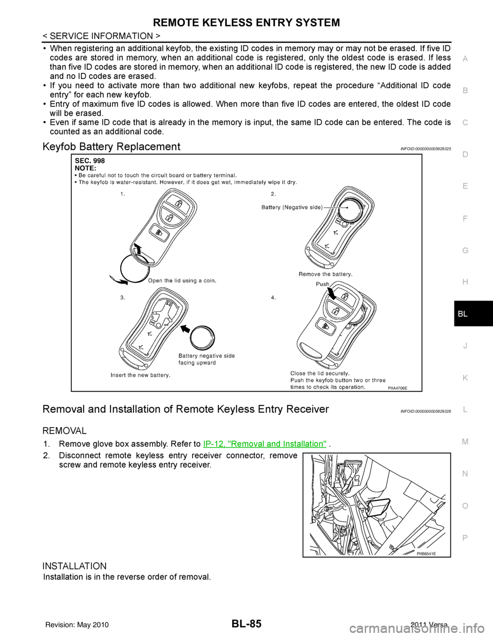
Keyfob Battery ReplacementINFOID:0000000005929325
Removal and Installation of Re mote Keyless Entry ReceiverINFOID:0000000005929326
REMOVAL
1. Remove glove box assembly. Refer to IP-12, "Removal and Installation" .
2. Disconnect remote keyless entry receiver connector, remove screw and remote keyless entry receiver.
INSTALLATION
Installation is in the reverse order of removal.
PIIA4706E
PIIB6541E
Revision: May 2010 2011 Versa
Page 598 of 3787

BL-88
< SERVICE INFORMATION >
INTELLIGENT KEY SYSTEM
System Description
INFOID:0000000005929328
• The Intelligent Key system is a system that makes it possible to lock and unlock the door locks (door lock/
unlock function), and start the engine (engine start func tion) by carrying around the Intelligent Key (without
some key operation), which operates based on the results of electronic ID verification using two-way com-
munications between the Intelligent Key and the vehicle (Intelligent Key unit).
• Vehicles equipped with a manual transmission include a key interlock solenoid located in the steering col- umn to prevent accidental shut-off of the ignition sw itch and locking of the steering wheel during driving con-
dition when the vehicle is moving.
CAUTION:
The driver should always carry the Intelligent Key
• Operation of the remote controller buttons on the Inte lligent Key also provides the same functions as the
remote control entry system. (Remote keyless entry functions)
• If an action that does not meet the operating conditions of the Intelligent Key system is taken, the buzzer
goes off to inform the driver. (Warning chime functions)
• When a door lock is locked or unlocked with request switch or remote controller button operation, the hazard
lamps flash and the buzzer (outside vehicle) sounds (Hazard and buzzer reminder function).
• Even if the Intelligent Key battery is completely discharged, the door locks can be locked and unlocked and the engine started with the mechanical key built into the Intelligent Key.
• The settings for each function can be changed with the CONSULT-III.
• If an Intelligent Key is lost, a new Intelligent Key can be registered. A maximum of 4 Intelligent Keys can be registered.
• It has been made possible to diagnose the system and r egister an Intelligent Key with the CONSULT-III.
DOOR LOCK/UNLOCK FUNCTION
Only when pressing the request switch, it is possible to lock and unlock the door by carrying around the Intelli-
gent Key (without some key operation).
System Diagram
10. Steering lock solenoid M6
(bottom view of steering column) 11. Key switch and ignition knob switch M73
(with CVT or A/T) 12. Key switch and ignition knob switch M73
(with M/T)
13. CVT or A/T shift selector (park posi- tion switch) M38
(without M/T) 14. Intelligent key warning buzzer (front
door LH) D6
(view with front door finisher LH re-
moved) 15. Front outside antenna LH D10, RH D106
16. Front door request switch LH D5, RH D103 17. Front door lock assembly LH (door un-
lock sensor) D14 18. Front door switch LH B8, RH B108
19. Rear door switch LH B6, RH B116 20. Front console antenna B125 (view of front console without arm rest
removed)21. Front console antenna B125
(view of front console with arm rest re-
moved)
22. Rear floor antenna B126 (behind rear seat) 23. Trunk opener request switch B129
(sedan) 24. Back door request switch D406
(hatchback)
25. Back door lock assembly (back door switch) D405 (hatchback view
with back door open) 26. Rear bumper antenna B2
(view with rear fascia removed) 27. Intelligent Key warn
ing buzzer (trunk) B32
(sedan)
LIIA2926E
Revision: May 2010 2011 Versa
Page 603 of 3787
INTELLIGENT KEY SYSTEMBL-93
< SERVICE INFORMATION >
C
DE
F
G H
J
K L
M A
B
BL
N
O P
Even if Intelligent Key battery runs down, Intelligent key unit can start engine with mechanical key built Intelli-
gent Key. For details, refer toBL-246
.
All of the originally supplied Intelligent Key IDs (exc ept for key) have been registered in Intelligent Key system.
If requested by the vehicle owner, a maximum of four Intelligent Key IDs can be registered into the Intelligent
Key system components.
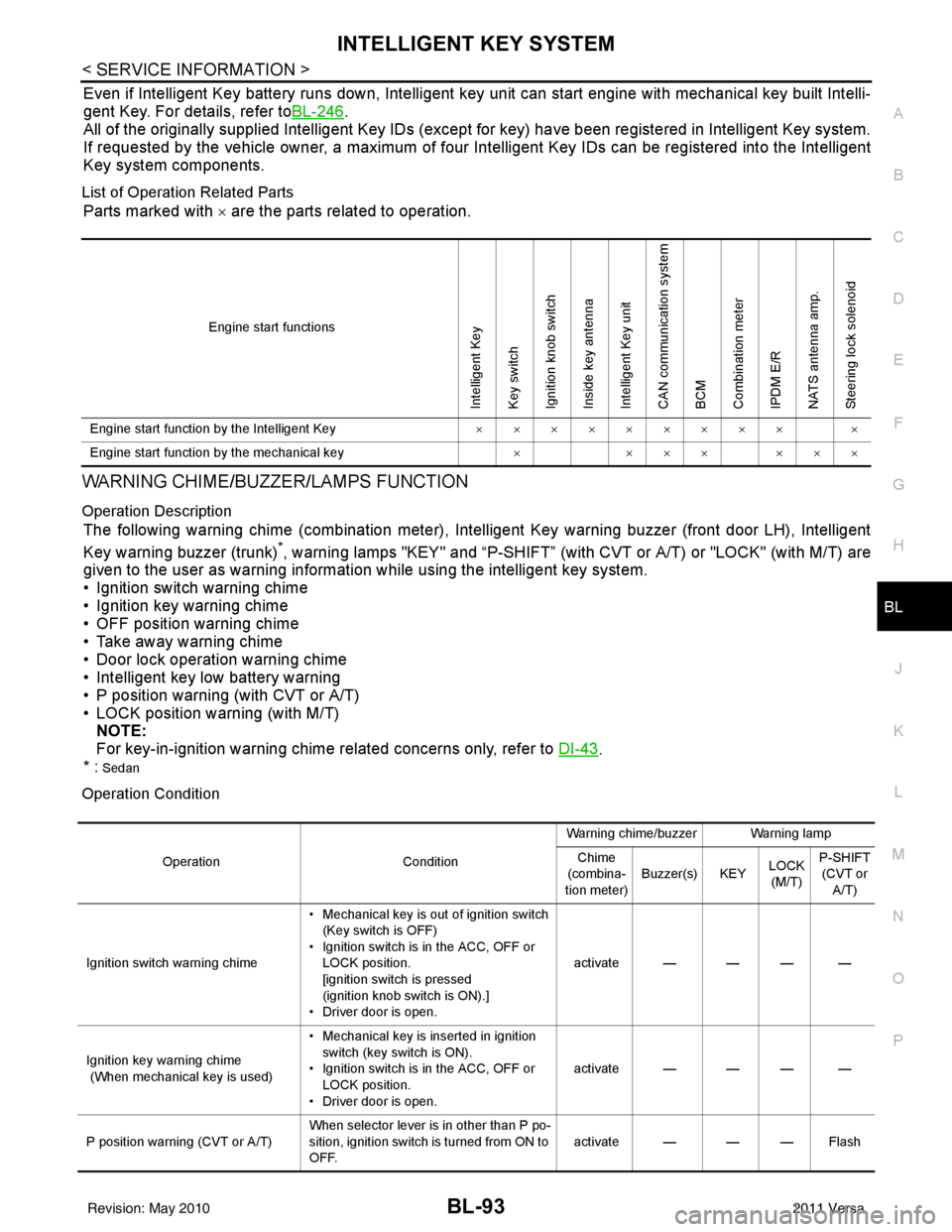
List of Operation Related Parts
Parts marked with × are the parts related to operation.
WARNING CHIME/BUZZER/LAMPS FUNCTION
Operation Description
The following warning chime (combination meter), Intelligent Key warning buzzer (front door LH), Intelligent
Key warning buzzer (trunk)
*, warning lamps "KEY" and “P-SHIFT” (with CVT or A/T) or "LOCK" (with M/T) are
given to the user as warning informati on while using the intelligent key system.
• Ignition switch warning chime
• Ignition key warning chime
• OFF position warning chime
• Take away warning chime
• Door lock operation warning chime
• Intelligent key low battery warning
• P position warning (with CVT or A/T)
• LOCK position warning (with M/T) NOTE:
For key-in-ignition warning chime related concerns only, refer to DI-43
.
* :
Sedan
Operation Condition
Engine start functions
Intelligent Key
Key switch
Ignition knob switch
Inside key antenna
Intelligent Key unit
CAN communication system
BCM
Combination meter
IPDM E/R
NATS antenna amp.
Steering lock solenoid
Engine start function by the Intelligent Key ××××××××× ×
Engine start function by the mechanical key ×××× ×××
Operation ConditionWarning chime/buzzer Warning lamp
Chime
(combina-
tion meter) Buzzer(s) KEY
LOCK
(M/T) P-SHIFT
(CVT or A/T)
Ignition switch warning chime • Mechanical key is out of ignition switch
(Key switch is OFF)
• Ignition switch is in the ACC, OFF or LOCK position.
[ignition switch is pressed
(ignition knob switch is ON).]
• Driver door is open. activate — — — —
Ignition key warning chime
(When mechanical key is used) • Mechanical key is inserted in ignition
switch (key switch is ON).
• Ignition switch is in the ACC, OFF or
LOCK position.
• Driver door is open. activate — — — —
P position warning (CVT or A/T) When selector lever is in other than P po-
sition, ignition switch is turned from ON to
OFF. activate — — — Flash
Revision: May 2010
2011 Versa