2011 NISSAN LATIO ignition
[x] Cancel search: ignitionPage 1290 of 3787

WARNING CHIMEDI-51
< SERVICE INFORMATION >
C
DE
F
G H
I
J
L
M A
B
DI
N
O P
OK >> Replace BCM. Refer to BCS-19, "Removal and Installation of BCM".
NG >> Replace front door switch LH.
Key Switch Signal Inspection (Without Intelligent Key)INFOID:0000000005929199
1.CHECK FUSE
Check if the key switch and key lock solenoid 10A fuse [No. 14, located in the fuse block (J/B)] is blown.
OK or NG
OK >> GO TO 2.
NG >> Be sure to repair the cause of malfunction before installing new fuse. Refer to PG-4
.
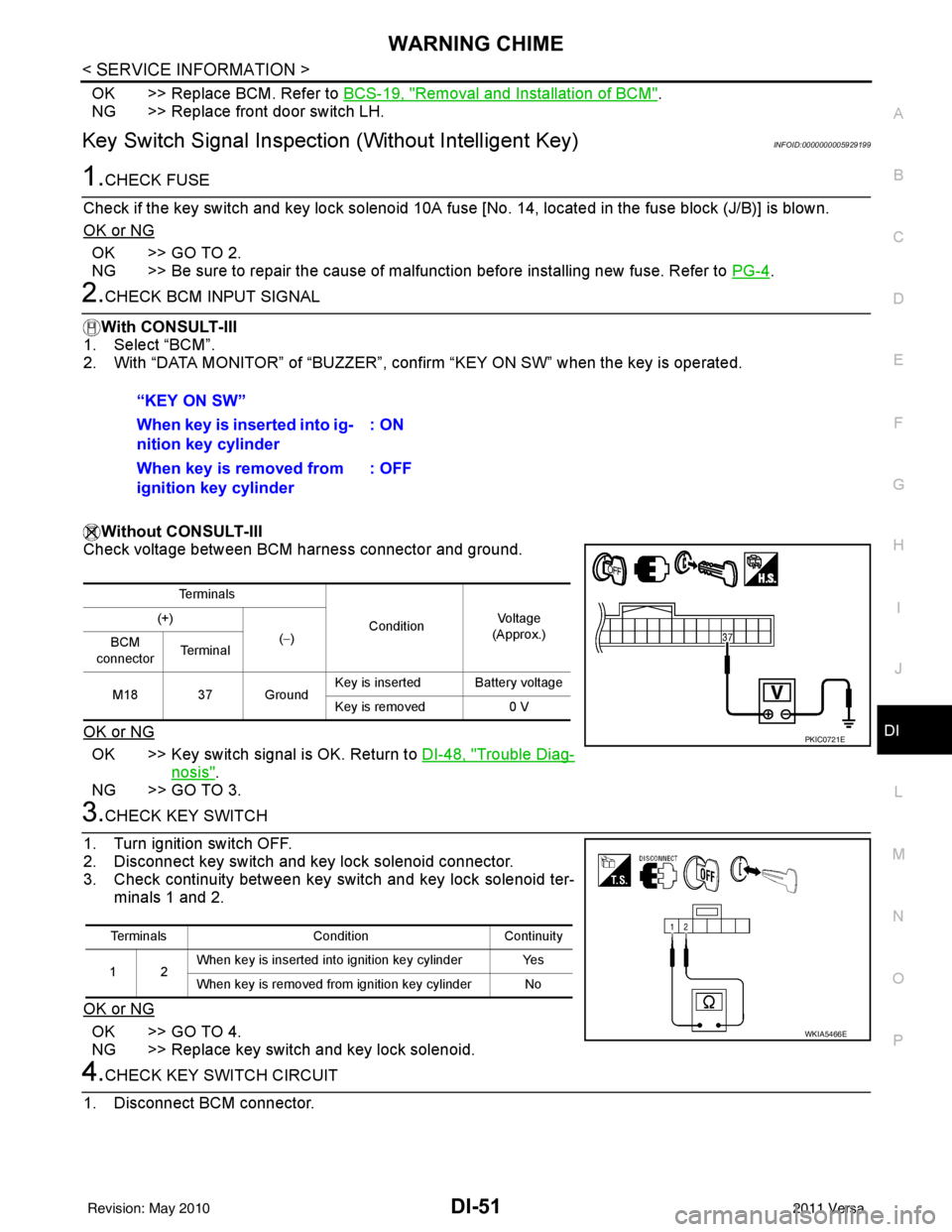
2.CHECK BCM INPUT SIGNAL
With CONSULT-III
1. Select “BCM”.
2. With “DATA MONITOR” of “BUZZER”, confirm “KEY ON SW” when the key is operated.
Without CONSULT-III
Check voltage between BCM harness connector and ground.
OK or NG
OK >> Key switch signal is OK. Return to DI-48, "Trouble Diag-
nosis".
NG >> GO TO 3.
3.CHECK KEY SWITCH
1. Turn ignition switch OFF.
2. Disconnect key switch and key lock solenoid connector.
3. Check continuity between key switch and key lock solenoid ter- minals 1 and 2.
OK or NG
OK >> GO TO 4.
NG >> Replace key switch and key lock solenoid.
4.CHECK KEY SWITCH CIRCUIT
1. Disconnect BCM connector. “KEY ON SW”
When key is inserted into ig-
nition key cylinder
: ON
When key is removed from
ignition key cylinder : OFF
Te r m i n a l s
ConditionVoltag e
(Approx.)
(+)
(−)
BCM
connector Te r m i n a l
M18 37 Ground Key is inserted Battery voltage
Key is removed
0 V
PKIC0721E
Terminals ConditionContinuity
12 When key is inserted into ignition key cylinder Yes
When key is removed from ignition key cylinder No
WKIA5466E
Revision: May 2010
2011 Versa
Page 1291 of 3787

DI-52
< SERVICE INFORMATION >
WARNING CHIME
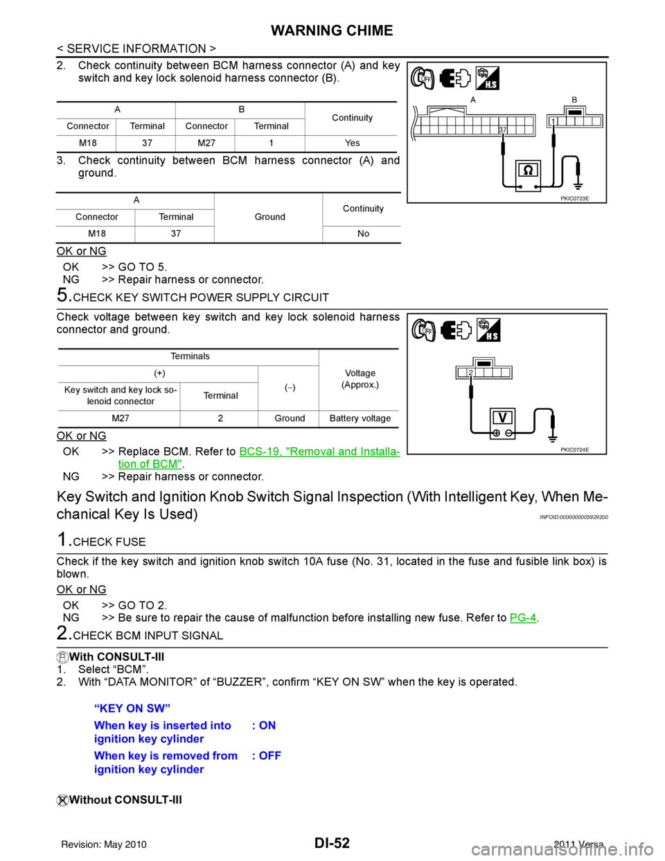
2. Check continuity between BCM harness connector (A) and keyswitch and key lock solenoid harness connector (B).
3. Check continuity between BCM harness connector (A) and ground.
OK or NG
OK >> GO TO 5.
NG >> Repair harness or connector.
5.CHECK KEY SWITCH PO WER SUPPLY CIRCUIT
Check voltage between key switch and key lock solenoid harness
connector and ground.
OK or NG
OK >> Replace BCM. Refer to BCS-19, "Removal and Installa-
tion of BCM".
NG >> Repair harness or connector.
Key Switch and Ignition Knob Switch Signal Inspection (With Intelligent Key, When Me-
chanical Key Is Used)
INFOID:0000000005929200
1.CHECK FUSE
Check if the key switch and ignition knob switch 10A fuse (No. 31, located in the fuse and fusible link box) is
blown.
OK or NG
OK >> GO TO 2.
NG >> Be sure to repair the cause of malfunction before installing new fuse. Refer to PG-4
.
2.CHECK BCM INPUT SIGNAL
With CONSULT-III
1. Select “BCM”.
2. With “DATA MONITOR” of “BUZZER”, c onfirm “KEY ON SW” when the key is operated.
Without CONSULT-III
AB Continuity
Connector Terminal Connector Terminal
M18 37 M27 1Yes
A GroundContinuity
Connector Terminal
M18 37 No
PKIC0723E
Te r m i n a l s
Voltage
(Approx.)
(+)
(−)
Key switch and key lock so-
lenoid connector Te r m i n a l
M27 2Ground Battery voltage
PKIC0724E
“KEY ON SW”
When key is inserted into
ignition key cylinder : ON
When key is removed from
ignition key cylinder : OFF
Revision: May 2010
2011 Versa
Page 1292 of 3787

WARNING CHIMEDI-53
< SERVICE INFORMATION >
C
DE
F
G H
I
J
L
M A
B
DI
N
O P
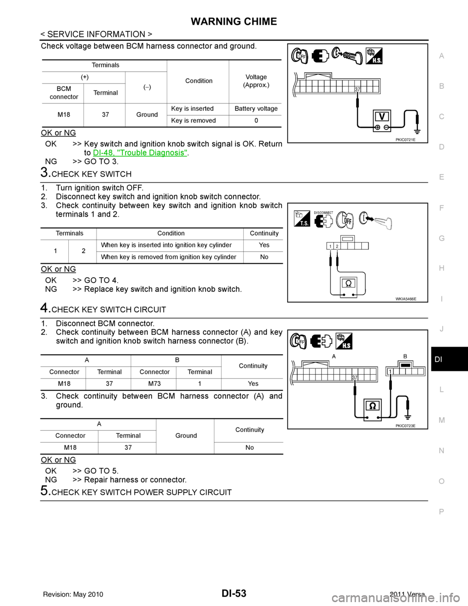
Check voltage between BCM harness connector and ground.
OK or NG
OK >> Key switch and ignition knob switch signal is OK. Return to DI-48, "
Trouble Diagnosis".
NG >> GO TO 3.
3.CHECK KEY SWITCH
1. Turn ignition switch OFF.
2. Disconnect key switch and i gnition knob switch connector.
3. Check continuity between key switch and ignition knob switch
terminals 1 and 2.
OK or NG
OK >> GO TO 4.
NG >> Replace key switch and ignition knob switch.
4.CHECK KEY SWITCH CIRCUIT
1. Disconnect BCM connector.
2. Check continuity between BCM harness connector (A) and key switch and ignition knob switch harness connector (B).
3. Check continuity between BCM harness connector (A) and ground.
OK or NG
OK >> GO TO 5.
NG >> Repair harness or connector.
5.CHECK KEY SWITCH POWER SUPPLY CIRCUIT
Te r m i n a l s ConditionVol tag e
(Approx.)
(+)
(−)
BCM
connector Te r m i n a l
M18 37 Ground Key is inserted Battery voltage
Key is removed
0
PKIC0721E
Terminals ConditionContinuity
12 When key is inserted into ignition key cylinder Yes
When key is removed from ignition key cylinder No
WKIA5466E
AB
Continuity
Connector Terminal Connector Terminal
M183 7M 73 1 Y es
A GroundContinuity
Connector Terminal
M18 37 No
PKIC0723E
Revision: May 2010 2011 Versa
Page 1293 of 3787

DI-54
< SERVICE INFORMATION >
WARNING CHIME
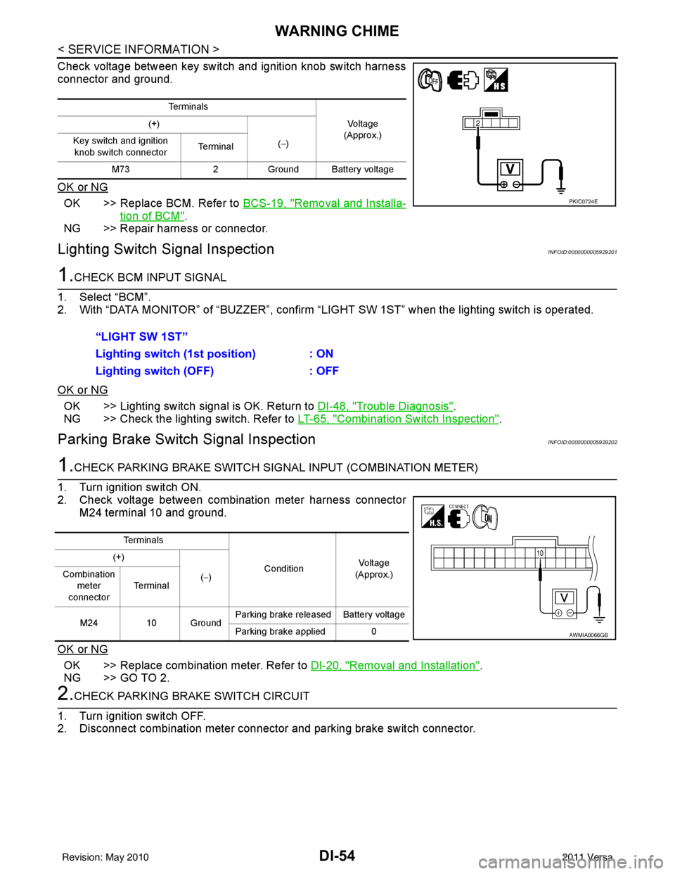
Check voltage between key switch and ignition knob switch harness
connector and ground.
OK or NG
OK >> Replace BCM. Refer to BCS-19, "Removal and Installa-
tion of BCM".
NG >> Repair harness or connector.
Lighting Switch Signal InspectionINFOID:0000000005929201
1.CHECK BCM INPUT SIGNAL
1. Select “BCM”.
2. With “DATA MONITOR” of “BUZZER”, confirm “LIG HT SW 1ST” when the lighting switch is operated.
OK or NG
OK >> Lighting switch signal is OK. Return to DI-48, "Trouble Diagnosis".
NG >> Check the lighting switch. Refer to LT-65, "
Combination Switch Inspection".
Parking Brake Switch Signal InspectionINFOID:0000000005929202
1.CHECK PARKING BRAKE SWITCH SIGNAL INPUT (COMBINATION METER)
1. Turn ignition switch ON.
2. Check voltage between combination meter harness connector M24 terminal 10 and ground.
OK or NG
OK >> Replace combination meter. Refer to DI-20, "Removal and Installation".
NG >> GO TO 2.
2.CHECK PARKING BRAKE SWITCH CIRCUIT
1. Turn ignition switch OFF.
2. Disconnect combination meter connector and parking brake switch connector.
Te r m i n a l s
Vo l ta g e
(Approx.)
(+)
(−)
Key switch and ignition
knob switch connector Te r m i n a l
M73 2Ground Battery voltage
PKIC0724E
“LIGHT SW 1ST”
Lighting switch ( 1st position) : ON
Lighting switch (OFF) : OFF
Te r m i n a l s
ConditionVoltag e
(Approx.)
(+)
(−)
Combination
meter
connector Te r m i n a l
M24 10 Ground Parking brake released Battery voltage
Parking brake applied 0
AWMIA0066GB
Revision: May 2010
2011 Versa
Page 1295 of 3787

EC-1
ENGINE
C
DE
F
G H
I
J
K L
M
SECTION EC
A
EC
N
O P
CONTENTS
ENGINE CONTROL SYSTEM
HR16DE
BASIC INSPECTION ....... ............................
15
DIAGNOSIS AND REPAIR WORK FLOW .... ....15
Work Flow ........................................................... ....15
Diagnostic Work Sheet ............................................18
INSPECTION AND ADJUSTMENT ....................20
BASIC INSPECTION .................................................20
BASIC INSPECTION : Spec ial Repair Require-
ment .................................................................... ....
20
ADDITIONAL SERVICE WHEN REPLACING
CONTROL UNIT .................................................... ....
23
ADDITIONAL SERVICE WHEN REPLACING
CONTROL UNIT : Description ................................
23
ADDITIONAL SERVICE WHEN REPLACING
CONTROL UNIT : Special Repair Requirement .....
23
IDLE SPEED .......................................................... ....24
IDLE SPEED : Description ........................ ..............24
IDLE SPEED : Special R epair Requirement ...........24
IGNITION TIMING .................................................. ....24
IGNITION TIMING : Description ..............................24
IGNITION TIMING : Special Repair Requirement ....24
VIN REGISTRATION ............................................. ....24
VIN REGISTRATION : Description .........................24
VIN REGISTRATION : Special Repair Require-
ment ........................................................................
25
ACCELERATOR PEDAL RELEASED POSITION
LEARNING ............................................................ ....
25
ACCELERATOR PEDAL RELEASED POSITION
LEARNING : Description .........................................
25
ACCELERATOR PEDAL RELEASED POSITION
LEARNING : Special Repair Requirement ..............
25
THROTTLE VALVE CLOSED POSITION LEARN-
ING ......................................................................... ....
25
THROTTLE VALVE CLOSED POSITION
LEARNING : Description .........................................
25
THROTTLE VALVE CLOSED POSITION
LEARNING : Special Repair Requirement ..............
25
IDLE AIR VOLUME LEARNING ............................ ....25
IDLE AIR VOLUME LEARNING : Description .........25
IDLE AIR VOLUME LEARNI NG : Special Repair
Requirement ........................................................ ....
26
MIXTURE RATIO SELF-LEARNING VALUE
CLEAR ................................................................... ....
27
MIXTURE RATIO SELF-LEARNING VALUE
CLEAR : Description ................................................
27
MIXTURE RATIO SELF-LEARNING VALUE
CLEAR : Special Repair Requirement .....................
27
HOW TO SET SRT CODE ................................29
Description ...............................................................29
SRT Set Driving Pattern ..........................................30
Work Procedure .......................................................32
HOW TO ERASE PERMANENT DTC ..............34
Description ...............................................................34
Work Procedure (Group A) ......................................35
Work Procedure (Group B) ......................................37
FUNCTION DIAGNOSIS ..............................40
ENGINE CONTRO L SYSTEM ..........................40
System Diagram ................................................. ....40
System Description ..................................................41
Component Parts Location ....................................41
Component Description ...........................................45
MULTIPORT FUEL INJECTION SYSTEM .......47
System Diagram .....................................................47
System Description ..................................................47
Component Parts Location ....................................50
Component Description ...........................................54
ELECTRIC IGNITION SYSTEM ........................56
Revision: May 2010 2011 Versa
Page 1300 of 3787

EC-6
P2119 ELECTRIC THROTTLE CONTROL
ACTUATOR .....................................................
400
Description ........................................................... ..400
DTC Logic ..............................................................400
Diagnosis Procedure .............................................400
Special Repair Requirement ..................................401
P2122, P2123 APP SENSOR ......................... .402
Description ........................................................... ..402
DTC Logic ..............................................................402
Wiring Diagram ......................................................403
Diagnosis Procedure .............................................403
Component Inspection ...........................................405
Special Repair Requirement ..................................405
P2127, P2128 APP SENSOR ......................... .406
Description ........................................................... ..406
DTC Logic ..............................................................406
Wiring Diagram ......................................................407
Diagnosis Procedure .............................................407
Component Inspection ...........................................409
Special Repair Requirement ..................................410
P2135 TP SENSOR ........................................ .411
Description ........................................................... ..411
DTC Logic ..............................................................411
Wiring Diagram ......................................................412
Diagnosis Procedure .............................................412
Component Inspection ...........................................414
Special Repair Requirement ..................................414
P2138 APP SENSOR ..................................... .415
Description ........................................................... ..415
DTC Logic ..............................................................415
Wiring Diagram ......................................................416
Diagnosis Procedure .............................................416
Component Inspection ...........................................419
Special Repair Requirement ..................................419
P2A00 A/F SENSOR 1 ................................... .420
Description ........................................................... ..420
DTC Logic ..............................................................420
Wiring Diagram ......................................................421
Diagnosis Procedure .............................................422
COOLING FAN ................................................425
Description ........................................................... ..425
Component Function Check ..................................425
Wiring Diagram ......................................................426
Diagnosis Procedure .............................................427
Component Inspection ...........................................429
ELECTRICAL LOAD SIGNAL .........................431
Description ........................................................... ..431
Component Function Check ..................................431
Diagnosis Procedure .............................................431
FUEL INJECTOR .............................................433
Description ........................................................... ..433
Component Function Check ..................................433
Wiring Diagram ......................................................434
Diagnosis Procedure ............................................ .434
Component Inspection ..........................................435
FUEL PUMP .....................................................437
Description ........................................................... .437
Component Function Check .................................437
Wiring Diagram .....................................................438
Diagnosis Procedure .............................................438
Component Inspection ..........................................440
IGNITION SIGNAL ............................................442
Description ........................................................... .442
Component Function Check .................................442
Wiring Diagram .....................................................443
Diagnosis Procedure .............................................444
Component Inspection (Ignition Coil with Power
Transistor) ............................................................ .
447
Component Inspection (Condenser-2) ..................448
MALFUNCTION INDICATOR LAMP ................449
Description ........................................................... .449
Component Function Check .................................449
Wiring Diagram .....................................................450
Diagnosis Procedure .............................................451
ON BOARD REFUELING VAPOR RECOV-
ERY (ORVR) .....................................................
453
Description ........................................................... .453
Component Function Check .................................453
Diagnosis Procedure .............................................453
Component Inspection (Refueling EVAP vapor cut
valve) ................................................................... .
456
Component Inspection (Drain filter) ......................458
POSITIVE CRANKCASE VENTILATION .........459
Description ........................................................... .459
Component Inspection ..........................................459
REFRIGERANT PRESSURE SENSOR ...........460
Description ........................................................... .460
Component Function Check .................................460
Wiring Diagram .....................................................461
Diagnosis Procedure .............................................461
ECU DIAGNOSIS ......................................464
ECM ................................................................ ..464
Reference Value .................................................. .464
Wiring Diagram — ENGINE CONTROL SYSTEM
— ..........................................................................
474
Fail Safe ...............................................................475
DTC Inspection Priority Chart .............................477
DTC Index ............................................................478
Test Value and Test Limit .....................................481
SYMPTOM DIAGNOSIS ...........................488
ENGINE CONTROL SYSTEM SYMPTOMS .. ..488
Symptom Table .................................................... .488
NORMAL OPERATING CONDITION ...............492
Revision: May 2010 2011 Versa
Page 1301 of 3787

EC-7
C
DE
F
G H
I
J
K L
M
EC A
N
O P
Description ..........................................................
..
492
PRECAUTION ............................................493
PRECAUTIONS .............................................. ..493
Precaution for Supplemental Restraint System
(SRS) "AIR BAG" and "SEAT BELT PRE-TEN-
SIONER" ............................................................. ..
493
Precaution for Procedure without Cowl Top Cover ..493
On Board Diagnosis (OBD) System of Engine and
A/T .........................................................................
493
General Precautions .............................................494
PREPARATION .........................................497
PREPARATION .............................................. ..497
Special Service Tools .......................................... ..497
Commercial Service Tools ....................................497
ON-VEHICLE MAINTENANCE ..................499
FUEL PRESSURE .......................................... ..499
Inspection ............................................................ ..499
EVAP LEAK CHECK ........................................501
Inspection ............................................................ ..501
SERVICE DATA AND SPECIFICATIONS
(SDS) ......... ................................. ................
503
SERVICE DATA AND SPECIFICATIONS
(SDS) .............................................................. ..
503
Idle Speed ........................................................... ..503
Ignition Timing .......................................................503
Calculated Load Value ..........................................503
Mass Air Flow Sensor ...........................................503
MR18DE
SERVICE INFORMATION .. .......................
504
INDEX FOR DTC ............................................ ..504
U0101-U1001 ...................................................... ..504
P0011-P0075 ........................................................504
P0101-P0128 ........................................................504
P0130-P0183 ........................................................505
P0222-P0420 ........................................................505
P0441-P0463 ........................................................506
P0500-P0643 ........................................................506
P0705-P0734 ........................................................507
P0740-P0840 ........................................................507
P0850-P1574 ........................................................508
P1610-P1615 ........................................................508
P1715-P1805 ........................................................508
P2100-P2A00 ........................................................509
PRECAUTIONS ................................................510
Precaution for Supplemental Restraint System
(SRS) "AIR BAG" and "SEAT BELT PRE-TEN-
SIONER" ............................................................. ..
510
Precaution Necessary for Steering Wheel Rota-
tion After Battery Disconnect ............................... ..
510
Precaution for Procedure without Cowl Top Cover ..511
On Board Diagnosis (OBD) System of Engine and
A/T, CVT ................................................................
511
Precaution .............................................................511
PREPARATION ...............................................515
Special Service Tool ..............................................515
Commercial Service Tool ......................................515
ENGINE CONTROL SYSTEM ........................517
Schematic ............................................................ ..517
Multiport Fuel Injection (MFI) System ....................517
Electronic Ignition (EI) System ..............................520
Fuel Cut Control (at No Load and High Engine
Speed) ...................................................................
520
AIR CONDITIONING CUT CONTROL ............522
Input/Output Signal Chart ......................................522
System Description ................................................522
AUTOMATIC SPEED CONTROL DEVICE
(ASCD) ............................................................
523
System Description ................................................523
Component Description .........................................524
CAN COMMUNICATION .................................525
System Description ................................................525
EVAPORATIVE EMISSION SYSTEM .............526
Description .............................................................526
Component Inspection ...........................................528
How to Detect Fuel Vapor Leakage .......................530
ON BOARD REFUELING VAPOR RECOV-
ERY (ORVR) ....................................................
532
System Description ................................................532
Diagnosis Procedure .............................................532
Component Inspection ...........................................535
POSITIVE CRANKCASE VENTILATION .......538
Description .............................................................538
Component Inspection ...........................................538
NVIS (NISSAN VEHICLE IMMOBILIZER SYS-
TEM-NATS) .....................................................
540
Description .............................................................540
ON BOARD DIAGNOSTIC (OBD) SYSTEM ..541
Introduction ............................................................541
Two Trip Detection Logic .......................................541
Emission-related Diagnostic Information ...............542
Malfunction Indicator Lamp (MIL) ..........................565
OBD System Operation Chart ...............................568
BASIC SERVICE PROCEDURE .....................574
Basic Inspection ....................................................574
Idle Speed and Ignition Timing Check ...................578
Procedure After Replacing ECM ...........................579
VIN Registration ....................................................580
Accelerator Pedal Released Position Learning .....580
Throttle Valve Closed Position Learning ...............580
Revision: May 2010 2011 Versa
Page 1308 of 3787

EC-14
Wiring Diagram ....................................................1005
Diagnosis Procedure ...........................................1005
ELECTRICAL LOAD SIGNAL ........................1007
CONSULT-III Reference Value in Data Monitor
Mode ....................................................................
1007
Diagnosis Procedure ...........................................1007
FUEL INJECTOR ............................................1009
Component Description .......................................1009
CONSULT-III Reference Va lue in Data Monitor
Mode ....................................................................
1009
Wiring Diagram ....................................................1010
Diagnosis Procedure ...........................................1011
Component Inspection .........................................1013
Removal and Installation .....................................1013
FUEL PUMP ....................................................1014
Description ...........................................................1014
CONSULT-III Reference Va lue in Data Monitor
Mode ....................................................................
1014
Wiring Diagram ....................................................1015
Diagnosis Procedure ...........................................1016
Component Inspection .........................................1018
Removal and Installation .....................................1018
IGNITION SIGNAL ..........................................1019
Component Description .......................................1019
Wiring Diagram ....................................................1020
Diagnosis Procedure ............................................1023
Component Inspection .........................................1026
Removal and Installation ......................................1027
REFRIGERANT PRESSURE SENSOR .........1028
Component Description .......................................1028
Wiring Diagram ....................................................1029
Diagnosis Procedure ............................................1030
Removal and Installation ......................................1032
MIL AND DATA LINK CONNECTOR .............1033
Wiring Diagram ....................................................1033
SERVICE DATA AND SPECIFICATIONS
(SDS) ..............................................................
1035
Fuel Pressure .......................................................1035
Idle Speed and Ignition Timing ............................1035
Calculated Load Value .........................................1035
Mass Air Flow Sensor ..........................................1035
Intake Air Temperature Se nsor ............................1035
Engine Coolant Temperature Sensor ..................1035
Air Fuel Ratio (A/F) Sensor 1 Heater ...................1036
Heated Oxygen sensor 2 Heater .........................1036
Crankshaft Position Sensor (POS) ......................1036
Camshaft Position Sensor (PHASE) ....................1036
Throttle Control Motor ...... ....................................1036
Fuel Injector .........................................................1036
Fuel Pump ............................................................1036
Revision: May 2010 2011 Versa