2011 NISSAN LATIO lock
[x] Cancel search: lockPage 1253 of 3787

DI-14
< SERVICE INFORMATION >
COMBINATION METERS
NOTE:
Some items are not available due to vehicle specification.
*: The monitor will indicate “OFF” even though the brake warning lamp is on if either of the following conditions exist.
• The parking brake is engaged
• The brake fluid level is low
Trouble DiagnosisINFOID:0000000005929168
HOW TO PERFORM TROUBLE DIAGNOSIS
1. Confirm the symptom or customer complaint.
2. Perform preliminary check. Refer to "PRELIMINARY CHECK" .
3. According to the symptom chart, repair or replace the cause of the malfunction. Refer to DI-15, "
Symptom
Chart" .
4. Does the meter operate normally? If so, GO TO 5. If not, GO TO 2.
5. Inspection End.
PRELIMINARY CHECK
1.CHECK SELF-DIAGNOSIS OPERAT ION OF COMBINATION METER
Perform self-diagnosis of combination meter. Refer to DI-11, "
Self-Diagnosis Mode of Combination Meter" .
Does self
-diagnosis mode operate?
TURN IND [ON/OFF] X Indicates [ON/OFF] condition of turn indicator.
OIL W/L [ON/OFF] X Indicates [ON/OFF] condition of oil pressure warning lamp.
VDC/TCS IND [ON/OFF] X Indicates [ON/OFF] condition of VDC OFF indicator lamp.
ABS W/L [ON/OFF] X Indicates [ON/OFF] condition of ABS warning lamp.
SLIP IND [ON/OFF] X Indicates [ON/OFF] condition of SLIP indicator lamp.
BRAKE W/L [ON/OFF] X Indicates [ON/OFF] condition of brake warning lamp.*
KEY G/Y W/L [ON/OFF] X Indicates [ON/OFF] condition of KEY warning lamp (green).
KEY R W/L [ON/OFF] X Indicates [ON/OFF] condition of KEY warning lamp (red).
KEY KNOB W/L [ON/OFF] X Indicates [ON/OFF] condition of LOCK warning lamp.
PNP P SW [ON/OFF] XX Indicates [ON/OFF] condition of inhibitor P switch.
PNP N SW [ON/OFF] XX Indicates [ON/OFF] condition of inhibitor N switch.
O/D OFF SW [ON/OFF] X Indicates [ON/OFF] condition of O/D OFF switch.
BRAKE SW [ON/OFF] X Indicates [ON/OFF] condition of parking brake switch.
P RANGE IND [ON/OFF] XXIndicates [ON/OFF] condition of A/T or CVT shift P range indi-
cator.
R RANGE IND [ON/OFF] XXIndicates [ON/OFF] condition of A/T or CVT shift R range indi-
cator.
N RANGE IND [ON/OFF] XXIndicates [ON/OFF] condition of A/T or CVT shift N range indi-
cator.
D RANGE IND [ON/OFF] XXIndicates [ON/OFF] condition of A/T or CVT shift D range indi-
cator.
2 RANGE IND [ON/OFF] XX Indicates [ON/OFF] condition of A/T shift 2 range indicator.
L RANGE IND [ON/OFF] XX Indicates [ON/OFF] condition of CVT shift L range indicator.
1 RANGE IND [ON/OFF] XX Indicates [ON/OFF] condition of A/T shift 1 range indicator.
CRUISE IND [ON/OFF] X Indicates [ON/OFF] condition of CRUISE indicator.
SET IND [ON/OFF] X Indicates [ON/OFF] condition of SET indicator.
O/D OFF W/L [ON/OFF] X Indicates [ON/OFF] condition of O/D OFF indicator lamp.
EPS W/L [ON/OFF] X Indicates [ON/OFF] condition of EPS warning lamp.
Display item [Unit]
MAIN
SIGNALS SELECTION
FROM MENU Contents
Revision: May 2010
2011 Versa
Page 1282 of 3787

WARNING CHIMEDI-43
< SERVICE INFORMATION >
C
DE
F
G H
I
J
L
M A
B
DI
N
O P
WARNING CHIME
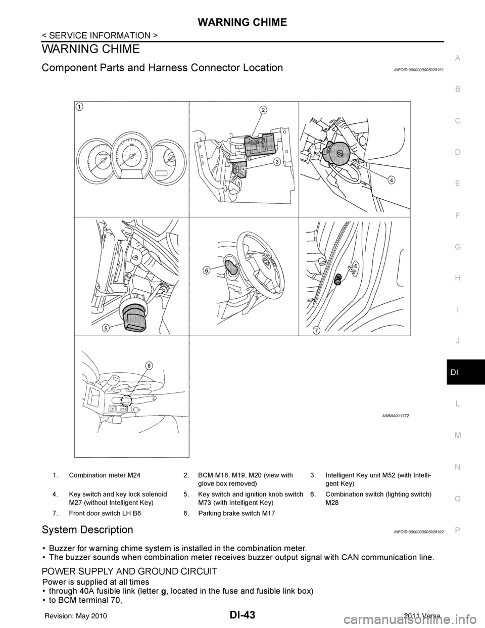
Component Parts and Har ness Connector LocationINFOID:0000000005929191
System DescriptionINFOID:0000000005929192
• Buzzer for warning chime system is installed in the combination meter.
• The buzzer sounds when combination meter receives buzzer output signal with CAN communication line.
POWER SUPPLY AND GROUND CIRCUIT
Power is supplied at all times
• through 40A fusible link (letter g, located in the fuse and fusible link box)
• to BCM terminal 70,
1. Combination meter M24 2. BCM M18, M19, M20 (view with
glove box removed) 3. Intelligent Key unit M52 (with Intelli-
gent Key)
4. Key switch and key lock solenoid M27 (without Intelligent Key) 5. Key switch and ignition knob switch
M73 (with Intelligent Key) 6. Combination switch (lighting switch)
M28
7. Front door switch LH B8 8. Parking brake switch M17
AWMIA0117ZZ
Revision: May 2010 2011 Versa
Page 1283 of 3787
![NISSAN LATIO 2011 Service Repair Manual DI-44
< SERVICE INFORMATION >
WARNING CHIME
• through 10A fuse [No. 8, located in the fuse block (J/B)]
• to BCM terminal 57,
• through 10A fuse [No. 13, located in the fuse block (J/B)]
• to NISSAN LATIO 2011 Service Repair Manual DI-44
< SERVICE INFORMATION >
WARNING CHIME
• through 10A fuse [No. 8, located in the fuse block (J/B)]
• to BCM terminal 57,
• through 10A fuse [No. 13, located in the fuse block (J/B)]
• to](/manual-img/5/57357/w960_57357-1282.png)
DI-44
< SERVICE INFORMATION >
WARNING CHIME
• through 10A fuse [No. 8, located in the fuse block (J/B)]
• to BCM terminal 57,
• through 10A fuse [No. 13, located in the fuse block (J/B)]
• to combination meter terminal 27.
With ignition switch in the ON or START position, power is supplied
• through 10A fuse [No. 6, located in the fuse block (J/B)]
• to BCM terminal 38,
• through 10A fuse [No. 3, located in the fuse block (J/B)]
• to combination meter terminal 28.
Ground is supplied
• to BCM terminal 67 and
• to combination meter terminals 21, 22 and 23
• through grounds M57 and M61.
IGNITION KEY WARNING CHIME (WITHOUT INTELLIGENT KEY)
With the key inserted into the key switch, and the ignition switch in the OFF or ACC position, when driver's
door is opened, the warning chime will sound.
• BCM detects key inserted into the ignition switch, and sends key warning signal to combination meter with CAN communication line.
• When combination meter receives key warning signal, it sounds warning chime.
IGNITION KEY WARNING CHIME (WITH INTELLIGENT KEY)
When Mechanical Key Is Used
With the key inserted into the key switch, and the igniti on switch in the LOCK or ACC position, when driver's
door is opened, the warning chime will sound.
• BCM detects key inserted into the ignition switch, and sends key warning signal to combination meter with
CAN communication line.
• When combination meter receives key warning signal, it sounds warning chime.
When Intelligent Key Is Carried With The Driver
Refer to BL-88, "System Description".
LIGHT WARNING CHIME
The warning chime sounds, when driver's door is opened (door switch ON) with lighting switch ON and the
ignition switch is in any position other than ON or START.
NOTE:
BCM detected lighting switch in the 1st or 2nd position, refer to LT-64, "
Combination Switch Reading Func-
tion".
• BCM detects headlamps are illuminated, and sends light warning signal to combination meter with CAN
communication lines.
WKIA5463E
WKIA5464E
Revision: May 2010 2011 Versa
Page 1290 of 3787

WARNING CHIMEDI-51
< SERVICE INFORMATION >
C
DE
F
G H
I
J
L
M A
B
DI
N
O P
OK >> Replace BCM. Refer to BCS-19, "Removal and Installation of BCM".
NG >> Replace front door switch LH.
Key Switch Signal Inspection (Without Intelligent Key)INFOID:0000000005929199
1.CHECK FUSE
Check if the key switch and key lock solenoid 10A fuse [No. 14, located in the fuse block (J/B)] is blown.
OK or NG
OK >> GO TO 2.
NG >> Be sure to repair the cause of malfunction before installing new fuse. Refer to PG-4
.
2.CHECK BCM INPUT SIGNAL
With CONSULT-III
1. Select “BCM”.
2. With “DATA MONITOR” of “BUZZER”, confirm “KEY ON SW” when the key is operated.
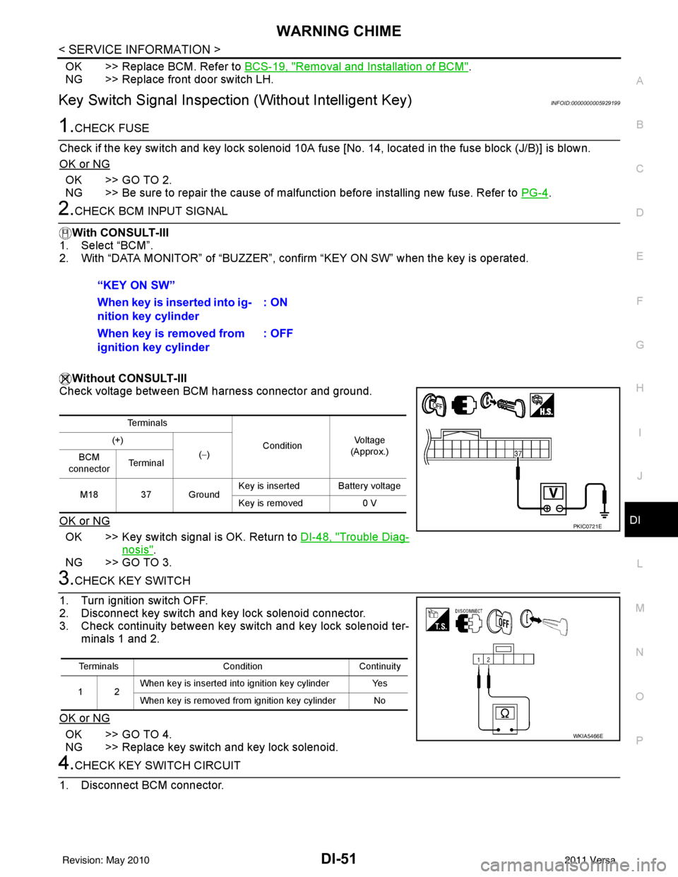
Without CONSULT-III
Check voltage between BCM harness connector and ground.
OK or NG
OK >> Key switch signal is OK. Return to DI-48, "Trouble Diag-
nosis".
NG >> GO TO 3.
3.CHECK KEY SWITCH
1. Turn ignition switch OFF.
2. Disconnect key switch and key lock solenoid connector.
3. Check continuity between key switch and key lock solenoid ter- minals 1 and 2.
OK or NG
OK >> GO TO 4.
NG >> Replace key switch and key lock solenoid.
4.CHECK KEY SWITCH CIRCUIT
1. Disconnect BCM connector. “KEY ON SW”
When key is inserted into ig-
nition key cylinder
: ON
When key is removed from
ignition key cylinder : OFF
Te r m i n a l s
ConditionVoltag e
(Approx.)
(+)
(−)
BCM
connector Te r m i n a l
M18 37 Ground Key is inserted Battery voltage
Key is removed
0 V
PKIC0721E
Terminals ConditionContinuity
12 When key is inserted into ignition key cylinder Yes
When key is removed from ignition key cylinder No
WKIA5466E
Revision: May 2010
2011 Versa
Page 1291 of 3787

DI-52
< SERVICE INFORMATION >
WARNING CHIME
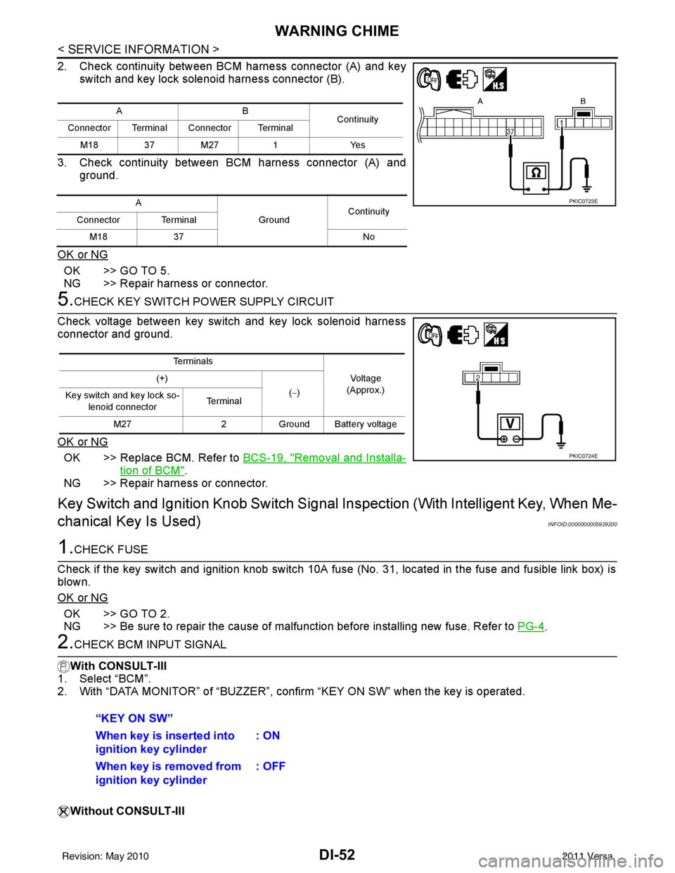
2. Check continuity between BCM harness connector (A) and keyswitch and key lock solenoid harness connector (B).
3. Check continuity between BCM harness connector (A) and ground.
OK or NG
OK >> GO TO 5.
NG >> Repair harness or connector.
5.CHECK KEY SWITCH PO WER SUPPLY CIRCUIT
Check voltage between key switch and key lock solenoid harness
connector and ground.
OK or NG
OK >> Replace BCM. Refer to BCS-19, "Removal and Installa-
tion of BCM".
NG >> Repair harness or connector.
Key Switch and Ignition Knob Switch Signal Inspection (With Intelligent Key, When Me-
chanical Key Is Used)
INFOID:0000000005929200
1.CHECK FUSE
Check if the key switch and ignition knob switch 10A fuse (No. 31, located in the fuse and fusible link box) is
blown.
OK or NG
OK >> GO TO 2.
NG >> Be sure to repair the cause of malfunction before installing new fuse. Refer to PG-4
.
2.CHECK BCM INPUT SIGNAL
With CONSULT-III
1. Select “BCM”.
2. With “DATA MONITOR” of “BUZZER”, c onfirm “KEY ON SW” when the key is operated.
Without CONSULT-III
AB Continuity
Connector Terminal Connector Terminal
M18 37 M27 1Yes
A GroundContinuity
Connector Terminal
M18 37 No
PKIC0723E
Te r m i n a l s
Voltage
(Approx.)
(+)
(−)
Key switch and key lock so-
lenoid connector Te r m i n a l
M27 2Ground Battery voltage
PKIC0724E
“KEY ON SW”
When key is inserted into
ignition key cylinder : ON
When key is removed from
ignition key cylinder : OFF
Revision: May 2010
2011 Versa
Page 1320 of 3787
![NISSAN LATIO 2011 Service Repair Manual EC-26
< BASIC INSPECTION >[HR16DE]
INSPECTION AND ADJUSTMENT
• Each time electric throttle control actuator or ECM is replaced.
• Idle speed or ignition timing is out of specification.
IDLE AIR VO NISSAN LATIO 2011 Service Repair Manual EC-26
< BASIC INSPECTION >[HR16DE]
INSPECTION AND ADJUSTMENT
• Each time electric throttle control actuator or ECM is replaced.
• Idle speed or ignition timing is out of specification.
IDLE AIR VO](/manual-img/5/57357/w960_57357-1319.png)
EC-26
< BASIC INSPECTION >[HR16DE]
INSPECTION AND ADJUSTMENT
• Each time electric throttle control actuator or ECM is replaced.
• Idle speed or ignition timing is out of specification.
IDLE AIR VOLUME LEARNING
: Special Repair RequirementINFOID:0000000005929760
1.PRECONDITIONING
Make sure that all of the following conditions are satisfied.
Learning will be cancelled if any of the follo wing conditions are missed for even a moment.
• Battery voltage: More than 12.9 V (At idle)
• Engine coolant temperature: 70 - 100 °C (158 - 212° F)
• Selector lever: P or N (A/T), Neutral (M/T)
• Electric load switch: OFF (Air conditioner, headlamp, rear window defogger)
On vehicles equipped with daytime light systems, if the parking brake is applied before the engine is
started the headlamp will not be illuminated.
• Steering wheel: Neutral (Straight-ahead position)
• Vehicle speed: Stopped
• Transmission: Warmed-up
- A/T models
• With CONSULT-III: Drive vehicle until “FLUID TEMP SE” in “DATA MONITOR” mode of “TRANSMISSION”
system indicates less than 0.9 V.
• Without CONSULT-III: Drive vehicle for 10 minutes.
- M/T models
• Drive vehicle for 10 minutes.
Do you have CONSULT-III?
YES >> GO TO 2.
NO >> GO TO 3.
2.IDLE AIR VOLUME LEARNING
With CONSULT-III
1. Perform Accelerator Pedal Released Position Learning. Refer to EC-25, "
ACCELERATOR PEDAL
RELEASED POSITION LEARNING : Special Repair Requirement".
2. Perform Throttle Valve Closed Position Learning. Refer to EC-25, "
THROTTLE VALVE CLOSED POSI-
TION LEARNING : Special Repair Requirement".
3. Start engine and warm it up to normal operating temperature.
4. Select “IDLE AIR VOL LEARN” in “WORK SUPPORT” mode.
5. Touch “START” and wait 20 seconds.
Is
“CMPLT” displayed on CONSULT-III screen?
YES >> GO TO 4.
NO >> GO TO 5.
3.IDLE AIR VOLUME LEARNING
Without CONSULT-III
NOTE:
• It is better to count the ti me accurately with a clock.
• It is impossible to switch the di agnostic mode when an accelerator pedal position sensor circuit has
a malfunction.
1. Perform Accelerator Pedal Released Position Learning. Refer to EC-25, "
ACCELERATOR PEDAL
RELEASED POSITION LEARNING : Special Repair Requirement".
2. Perform Throttle Valve Closed Position Learning. Refer to EC-25, "
THROTTLE VALVE CLOSED POSI-
TION LEARNING : Special Repair Requirement".
3. Start engine and warm it up to normal operating temperature.
4. Turn ignition switch OFF and wait at least 10 seconds.
5. Confirm that accelerator pedal is fully releas ed, turn ignition switch ON and wait 3 seconds.
6. Repeat the following procedure quickly five times within 5 seconds.
- Fully depress the accelerator pedal.
- Fully release the accelerator pedal.
7. Wait 7 seconds, fully depress the accelerator pedal and keep it for approx. 20 seconds until the MIL stops
blinking and turned ON.
8. Fully release the accelerator pedal within 3 seconds after the MIL turned ON.
Revision: May 2010 2011 Versa
Page 1398 of 3787
![NISSAN LATIO 2011 Service Repair Manual EC-104
< FUNCTION DIAGNOSIS >[HR16DE]
DIAGNOSIS SYSTEM (ECM)
• ECM blinks MIL for about 10 seconds if all SRT codes are not set.
MALFUNCTION WARNING MODE
Description
In this function ECM turns on or NISSAN LATIO 2011 Service Repair Manual EC-104
< FUNCTION DIAGNOSIS >[HR16DE]
DIAGNOSIS SYSTEM (ECM)
• ECM blinks MIL for about 10 seconds if all SRT codes are not set.
MALFUNCTION WARNING MODE
Description
In this function ECM turns on or](/manual-img/5/57357/w960_57357-1397.png)
EC-104
< FUNCTION DIAGNOSIS >[HR16DE]
DIAGNOSIS SYSTEM (ECM)
• ECM blinks MIL for about 10 seconds if all SRT codes are not set.
MALFUNCTION WARNING MODE
Description
In this function ECM turns on or blinks MIL when it detects a malfunction in the emission control system com-
ponents and/or the powertrain control components (which affe
ct vehicle emissions) to inform the driver that a
malfunction has been detected.
Operation Procedure
1. Turn ignition switch ON.
2. Check that MIL illuminates.
If it remains OFF, check MIL circuit. Refer to EC-451, "
Diagnosis Procedure".
3. Start engine and let it idle. • For two trip detection logic diagnoses, ECM turns on MIL when it detects the same malfunction twice inthe two consecutive driving cycles.
• For 1st trip detection logic diagnoses, ECM turns on MIL when it detects a malfunction in one driving
cycle.
• ECM blinks MIL when it detects a malfunction t hat may damage the three way catalyst (misfire).
SELF-DIAGNOSTIC RESULTS MODE
Description
This function allows to indicate DTCs or 1st trip DT Cs stored in ECM according to the number of times MIL is
blinking.
How to Set Self-diagnostic Results Mode
NOTE:
• It is better to count the time accurately with a clock.
• It is impossible to switch the diagnostic mode when an accelerator pedal position sensor circuit has a mal-
function.
• After ignition switch is turned off, ECM is always released from the “self-diagnostic results” mode.
1. Confirm that accelerator pedal is fully releas ed, turn ignition switch ON and wait 3 seconds.
2. Repeat the following procedure quickly five times within 5 seconds. • Fully depress the accelerator pedal.
• Fully release the accelerator pedal.
3. Wait 7 seconds, fully depress the accelerator pedal and keep it depressed for approx. 10 seconds until the MIL starts blinking.
NOTE:
Do not release the accelerator pedal for 10 seconds if MIL starts blinking during this period. This blinking
is displaying SRT status and is continued for another 10 seconds.
4. Fully release the accelerator pedal. ECM has entered to “Self-diagnostic results” mode.
NOTE:
JMBIA1515GB
Revision: May 2010 2011 Versa
Page 1557 of 3787
![NISSAN LATIO 2011 Service Repair Manual P0327, P0328 KSEC-263
< COMPONENT DIAGNOSIS > [HR16DE]
C
D
E
F
G H
I
J
K L
M A
EC
NP
O
P0327, P0328 KS
DescriptionINFOID:0000000005929934
The knock sensor is attached to the cylinder block.
It senses NISSAN LATIO 2011 Service Repair Manual P0327, P0328 KSEC-263
< COMPONENT DIAGNOSIS > [HR16DE]
C
D
E
F
G H
I
J
K L
M A
EC
NP
O
P0327, P0328 KS
DescriptionINFOID:0000000005929934
The knock sensor is attached to the cylinder block.
It senses](/manual-img/5/57357/w960_57357-1556.png)
P0327, P0328 KSEC-263
< COMPONENT DIAGNOSIS > [HR16DE]
C
D
E
F
G H
I
J
K L
M A
EC
NP
O
P0327, P0328 KS
DescriptionINFOID:0000000005929934
The knock sensor is attached to the cylinder block.
It senses engine knocking using a piezoelectric element. A
knocking vibration from the cylinder blo ck is sensed as vibrational pressure. This pressure is converted into a
voltage signal and sent to the ECM.
DTC LogicINFOID:0000000005929935
DTC DETECTION LOGIC
DTC CONFIRMATION PROCEDURE
1.PRECONDITIONING
If DTC Confirmation Procedure has been previously conducted, always turn ignition switch OFF and wait at
least 10 seconds before conducting the next test.
TESTING CONDITION:
Before performing the following procedure, confirm that battery voltage is more than 10 V at idle.
>> GO TO 2.
2.PERFORM DTC CONFIRMATION PROCEDURE
1. Start engine and run it for at least 5 seconds at idle speed.
2. Check 1st trip DTC.
Is 1st trip DTC detected?
YES >> Go to EC-264, "Diagnosis Procedure".
NO >> INSPECTION END
DTC No. Trouble diagnosis name DTC detected conditionPossible cause
P0327 Knock sensor circuit low
input An excessively low voltage from the sensor is
sent to ECM.
• Harness or connectors
(The sensor circuit is open or shorted.)
• Knock sensor
P0328 Knock sensor circuit high
input An excessively high voltage from the sensor is
sent to ECM.
Revision: May 2010
2011 Versa