2011 NISSAN LATIO window
[x] Cancel search: windowPage 677 of 3787
FRONT DOOR LOCKBL-167
< SERVICE INFORMATION >
C
DE
F
G H
J
K L
M A
B
BL
N
O P
FRONT DOOR LOCK
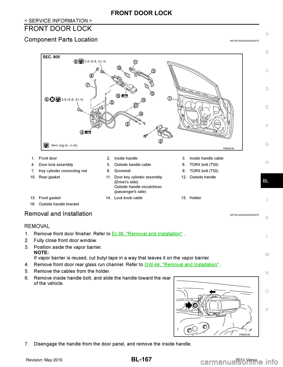
Component Parts LocationINFOID:0000000005929375
Removal and InstallationINFOID:0000000005929376
REMOVAL
1. Remove front door finisher. Refer to EI-36, "Removal and Installation" .
2. Fully close front door window.
3. Position aside the vapor barrier. NOTE:
If vapor barrier is reused, cut butyl tape in a way that leaves it on the vapor barrier.
4. Remove front door rear glass run channel. Refer to GW-44, "
Removal and Installation" .
5. Remove the cables from the holder.
6. Remove inside handle bolt, and slide the handle toward the rear of the vehicle.
7. Disengage the handle from the door panel, and remove the inside handle.
1. Front door 2. Inside handle3. Inside handle cable
4. Door lock assembly 5. Outside handle cable6. TORX bolt (T30)
7. Key cylinder connecting rod 8. Grommet9. TORX bolt (T30)
10. Rear gasket 11. Door key cylinder assembly
(Driver's side)
Outside handle escutcheon
(passenger's side) 12. Outside handle
13. Front gasket 14. Lock knob cable15. Holder
16. Outside handle bracket
PIIB6523E
PIIB6524E
Revision: May 2010 2011 Versa
Page 680 of 3787
BL-170
< SERVICE INFORMATION >
REAR DOOR LOCK
REAR DOOR LOCK
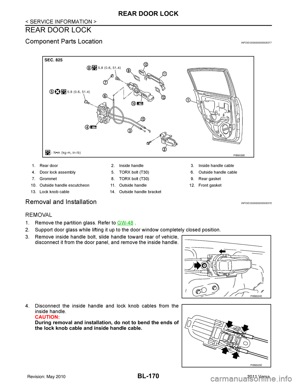
Component Parts LocationINFOID:0000000005929377
Removal and InstallationINFOID:0000000005929378
REMOVAL
1. Remove the partition glass. Refer to GW-48 .
2. Support door glass while lifting it up to the door window completely closed position.
3. Remove inside handle bolt, slide handle toward rear of vehicle, disconnect it from the door panel, and remove the inside handle.
4. Disconnect the inside handle and lock knob cables from the inside handle.
CAUTION:
During removal and installation , do not to bend the ends of
the lock knob cable and inside handle cable.
1. Rear door 2. Inside handle 3. Inside handle cable
4. Door lock assembly 5. TORX bolt (T30) 6. Outside handle cable
7. Grommet 8. TORX bolt (T30) 9. Rear gasket
10. Outside handle escutcheon 11. Outside handle12. Front gasket
13. Lock knob cable 14. Outside handle bracket
PIIB6530E
PIIB6524E
PIIB6525E
Revision: May 2010 2011 Versa
Page 683 of 3787
BACK DOOR LOCKBL-173
< SERVICE INFORMATION >
C
DE
F
G H
J
K L
M A
B
BL
N
O P
BACK DOOR LOCK
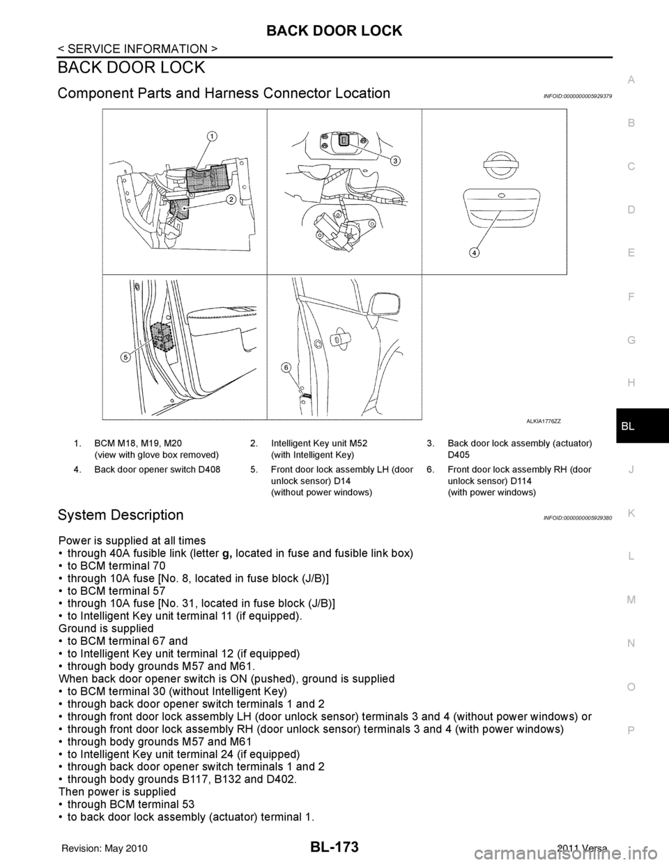
Component Parts and Har ness Connector LocationINFOID:0000000005929379
System DescriptionINFOID:0000000005929380
Power is supplied at all times
• through 40A fusible link (letter g, located in fuse and fusible link box)
• to BCM terminal 70
• through 10A fuse [No. 8, located in fuse block (J/B)]
• to BCM terminal 57
• through 10A fuse [No. 31, located in fuse block (J/B)]
• to Intelligent Key unit terminal 11 (if equipped).
Ground is supplied
• to BCM terminal 67 and
• to Intelligent Key unit terminal 12 (if equipped)
• through body grounds M57 and M61.
When back door opener switch is ON (pushed), ground is supplied
• to BCM terminal 30 (without Intelligent Key)
• through back door opener switch terminals 1 and 2
• through front door lock assembly LH (door unlock sensor) terminals 3 and 4 (without power windows) or
• through front door lock assembly RH (door unlock sensor) terminals 3 and 4 (with power windows)
• through body grounds M57 and M61
• to Intelligent Key unit terminal 24 (if equipped)
• through back door opener switch terminals 1 and 2
• through body grounds B117, B132 and D402.
Then power is supplied
• through BCM terminal 53
• to back door lock assembly (actuator) terminal 1.
ALKIA1776ZZ
1. BCM M18, M19, M20
(view with glove box removed) 2. Intelligent Key unit M52
(with Intelligent Key) 3. Back door lock assembly (actuator)
D405
4. Back door opener switch D408 5. Front door lock assembly LH (door unlock sensor) D14
(without power windows)6. Front door lock assembly RH (door
unlock sensor) D114
(with power windows)
Revision: May 2010 2011 Versa
Page 686 of 3787
BL-176
< SERVICE INFORMATION >
BACK DOOR LOCK
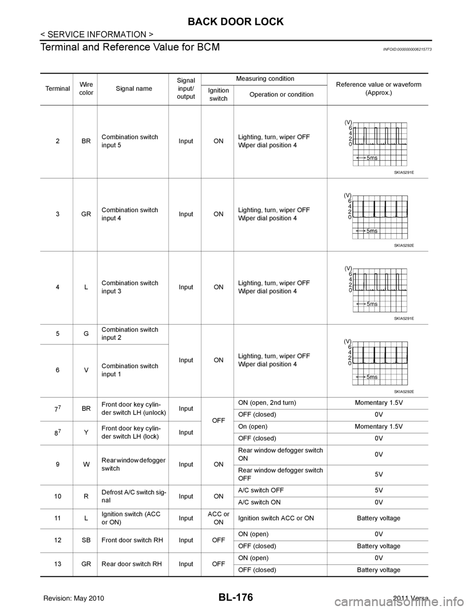
Terminal and Reference Value for BCM
INFOID:0000000006215773
Te r m i n a l Wire
color Signal name Signal
input/
output Measuring condition
Reference value or waveform
(Approx.)
Ignition
switch Operation or condition
2BR Combination switch
input 5
Input ONLighting, turn, wiper OFF
Wiper dial position 4
3GR Combination switch
input 4 Input ONLighting, turn, wiper OFF
Wiper dial position 4
4L Combination switch
input 3
Input ONLighting, turn, wiper OFF
Wiper dial position 4
5G Combination switch
input 2
Input ONLighting, turn, wiper OFF
Wiper dial position 4
6V Combination switch
input 1
7
7BR Front door key cylin-
der switch LH (unlock) Input
OFFON (open, 2nd turn)
Momentary 1.5V
OFF (closed) 0V
8
7Y Front door key cylin-
der switch LH (lock) InputOn (open)
Momentary 1.5V
OFF (closed) 0V
9W Rear window defogger
switch Input ONRear window defogger switch
ON
0V
Rear window defogger switch
OFF 5V
10 R Defrost A/C switch sig-
nal
Input ONA/C switch OFF
5V
A/C switch ON 0V
11 L Ignition switch (ACC
or ON) InputACC or
ON Ignition switch ACC or ON
Battery voltage
12 SB Front door switch RH Input OFF ON (open)
0V
OFF (closed) Battery voltage
13 GR Rear door switch RH Input OFF ON (open)
0V
OFF (closed) Battery voltage
SKIA5291E
SKIA5292E
SKIA5291E
SKIA5292E
Revision: May 2010 2011 Versa
Page 690 of 3787

BL-180
< SERVICE INFORMATION >
BACK DOOR LOCK
1: With Intelligent Key
2: Without Intelligent Key
3: Hatchback without Intelligent Key
4: Sedan without Intelligent Key
5: Hatchback
6: Sedan
7: With power door locks
8: With power windows
Terminal and Reference Value for Intelligent Key UnitINFOID:0000000006215775
63 BR Interior room lamp Output OFFAny door
switchON (open)
0V
OFF (closed) Battery voltage
65
7SB All door lock actuators
(lock) Output OFFOFF (neutral)
0V
ON (lock) Battery voltage
66
7G Front door lock actua-
tor RH, rear door lock
actuators LH/RH (un-
lock) Output OFFOFF (neutral)
0V
ON (unlock) Battery voltage
67 B Ground Input ON—0V
68
8L Power window power
supply (RAP)
Output —Ignition switch ON
Battery voltage
Within 45 seconds after igni-
tion switch OFF Battery voltage
More than 45 seconds after ig-
nition switch OFF 0V
When front door LH or RH is
open or power window timer
operates 0V
69
8P Battery power supply OutputOFF
— Battery voltage
70 Y Battery power supply Input OFF —Battery voltage
Te r m i n a l
Wire
color Signal name Signal
input/
output Measuring condition
Reference value or waveform
(Approx.)
Ignition
switch Operation or condition
Te r m i n a lWire
Color Item Condition
Voltage (V)Approx.
Ignition
Switch
Position Operation or Conditions
1R Steering lock solenoid
power supply
LOCK
— 5
2 L CAN-H —— —
3 P CAN-L —— —
4O Intelligent Key warning
buzzer LOCKOperate door request
switch. Buzzer OFF
Battery voltage
Sound buzzer 0
5G Front door request
switch LH —Press door request switch (driver side).
0
Other than above 5
6 Y Ignition switch (ON) ON —Battery voltage
7 LG Key switch LOCKInsert mechanical key into ignition switch. Battery voltage
Remove mechanical key from ignition
switch.
0
Revision: May 2010
2011 Versa
Page 693 of 3787
BACK DOOR LOCKBL-183
< SERVICE INFORMATION >
C
DE
F
G H
J
K L
M A
B
BL
N
O P
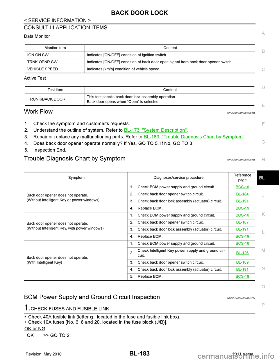
CONSULT-III APPLICATION ITEMS
Data Monitor
Active Test
Work FlowINFOID:0000000005929385
1. Check the symptom and customer's requests.
2. Understand the outline of system. Refer to BL-173, "
System Description".
3. Repair or replace any malfunctioning parts. Refer to BL-183, "
Trouble Diagnosis Chart by Symptom".
4. Does back door opener operate normally? If Yes, GO TO 5. If No, GO TO 3.
5. Inspection End.
Trouble Diagnosis Chart by SymptomINFOID:0000000005929386
BCM Power Supply and Gr ound Circuit InspectionINFOID:0000000006215774
1.CHECK FUSES AND FUSIBLE LINK
• Check 40A fusible link (letter g , located in the fuse and fusible link box).
• Check 10A fuses [No. 6, 8 and 20, lo cated in the fuse block (J/B)].
OK or NG
OK >> GO TO 2.
Monitor item Content
IGN ON SW Indicates [ON/OFF] condition of ignition switch.
TRNK OPNR SW Indicates [ON/OFF] condition of back door open signal from back door opener switch.
VEHICLE SPEED Indicates [km/h] condition of vehicle speed.
Test item Content
TRUNK/BACK DOOR This test checks back door lock assembly operation.
Back door opens when “Open” is selected.
Symptom
Diagnoses/service procedureReference
page
Back door opener does not operate.
(Without Intelligent Key or power windows) 1. Check BCM power supply and ground circuit.
BCS-16
2. Check back door opener switch circuit. BL-184
3. Check back door lock assembly (actuator) circuit.BL-191
4. Replace BCM.BCS-19
Back door opener does not operate.
(Without Intelligent Key, with power windows)1. Check BCM power supply and ground circuit.
BCS-162. Check back door opener switch circuit. BL-187
3. Check back door lock assembly (actuator) circuit.BL-191
4. Replace BCM.BCS-19
Back door opener does not operate.
(With Intelligent Key)1. Check BCM power supply and ground circuit.
BCS-16
2.Check Intelligent Key power supply and ground cir-
cuit.
BL-126
3. Check back door opener switch circuit.
BL-189
4. Check back door lock assembly (actuator) circuit.BL-191
5. Replace BCM.BCS-19
Revision: May 2010 2011 Versa
Page 694 of 3787
BL-184
< SERVICE INFORMATION >
BACK DOOR LOCK
NG >> If fuse is blown, be sure to eliminate cause of malfunction before installing new fuse. Refer to PG-
4, "Schematic" .
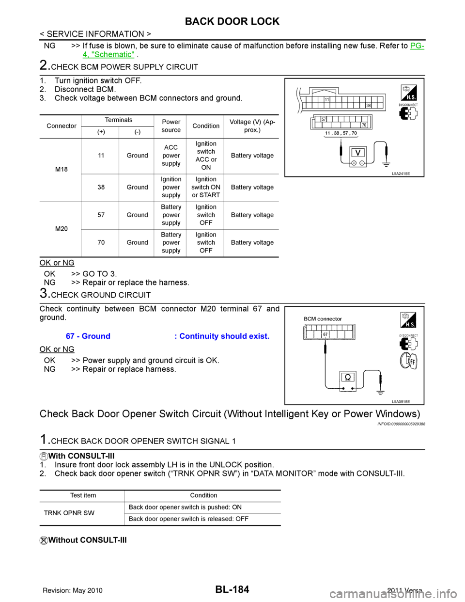
2.CHECK BCM POWER SUPPLY CIRCUIT
1. Turn ignition switch OFF.
2. Disconnect BCM.
3. Check voltage between BCM connectors and ground.
OK or NG
OK >> GO TO 3.
NG >> Repair or replace the harness.
3.CHECK GROUND CIRCUIT
Check continuity between BCM connector M20 terminal 67 and
ground.
OK or NG
OK >> Power supply and ground circuit is OK.
NG >> Repair or replace harness.
Check Back Door Opener Sw itch Circuit (Without Intelligent Key or Power Windows)
INFOID:0000000005929388
1.CHECK BACK DOOR OPENER SWITCH SIGNAL 1
With CONSULT-III
1. Insure front door lock assembly LH is in the UNLOCK position.
2. Check back door opener switch (“TRNK OPNR SW”) in “DATA MONITOR” mode with CONSULT-III.
Without CONSULT-III
Connector Te r m i n a l s
Power
source Condition Voltage (V) (Ap-
prox.)
(+) (-)
M18 11 Ground
ACC
power
supply Ignition
switch
ACC or
ON Battery voltage
38 Ground Ignition
power
supply Ignition
switch ON or START Battery voltage
M20 57 Ground
Battery
power
supply Ignition
switch OFF Battery voltage
70 Ground Battery
power
supply Ignition
switch
OFF Battery voltage
LIIA2415E
67 - Ground
: Continuity should exist.
LIIA0915E
Test item Condition
TRNK OPNR SW Back door opener switch is pushed: ON
Back door opener switch is released: OFF
Revision: May 2010
2011 Versa
Page 697 of 3787
BACK DOOR LOCKBL-187
< SERVICE INFORMATION >
C
DE
F
G H
J
K L
M A
B
BL
N
O P
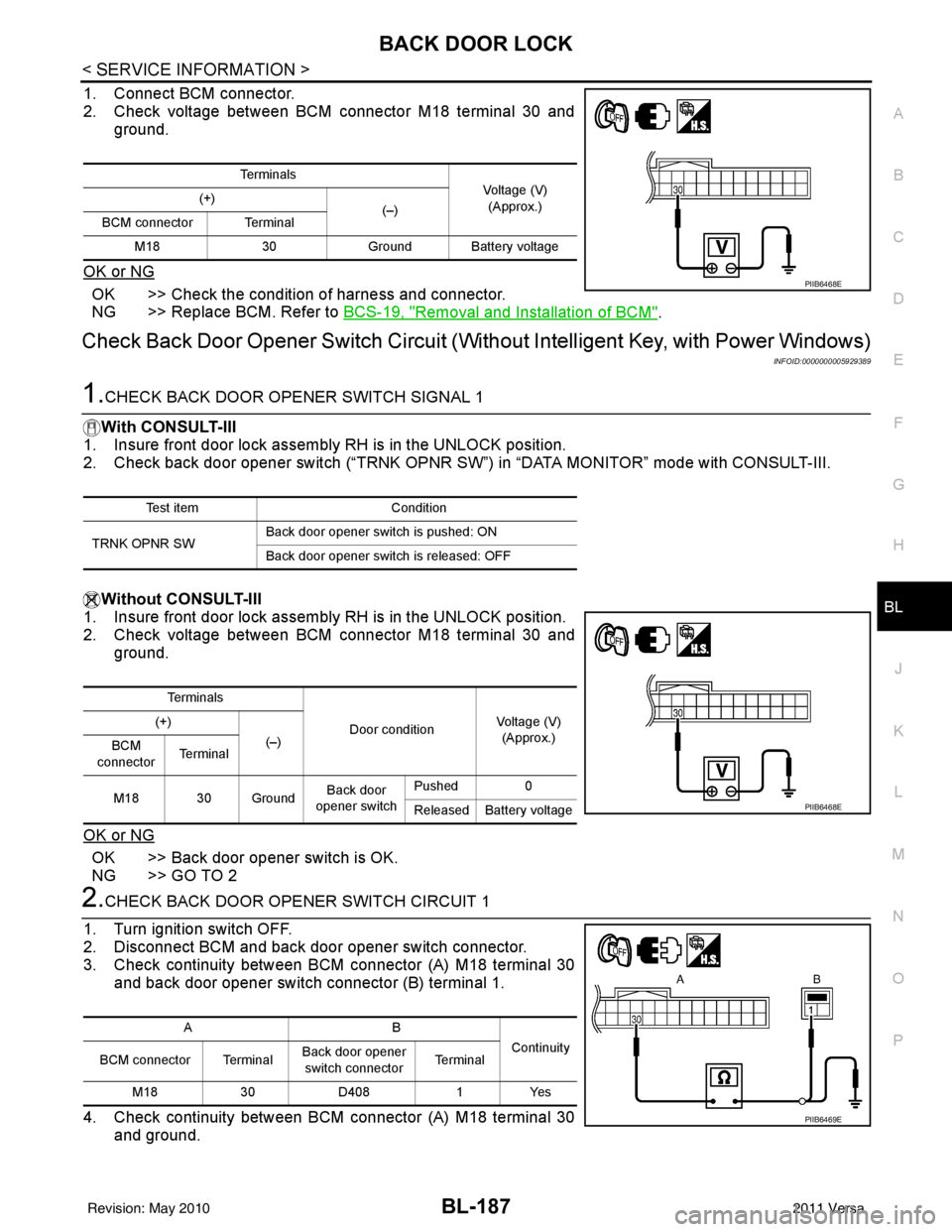
1. Connect BCM connector.
2. Check voltage between BCM connector M18 terminal 30 and ground.
OK or NG
OK >> Check the condition of harness and connector.
NG >> Replace BCM. Refer to BCS-19, "
Removal and Installation of BCM".
Check Back Door Opener Switch Circuit (Without Inte lligent Key, with Power Windows)
INFOID:0000000005929389
1.CHECK BACK DOOR OPENER SWITCH SIGNAL 1
With CONSULT-III
1. Insure front door lock assembly RH is in the UNLOCK position.
2. Check back door opener switch (“TRNK OPNR SW ”) in “DATA MONITOR” mode with CONSULT-III.
Without CONSULT-III
1. Insure front door lock assembly RH is in the UNLOCK position.
2. Check voltage between BCM connector M18 terminal 30 and
ground.
OK or NG
OK >> Back door opener switch is OK.
NG >> GO TO 2
2.CHECK BACK DOOR OPENER SWITCH CIRCUIT 1
1. Turn ignition switch OFF.
2. Disconnect BCM and back door opener switch connector.
3. Check continuity between BCM connector (A) M18 terminal 30 and back door opener switch connector (B) terminal 1.
4. Check continuity between BCM connector (A) M18 terminal 30 and ground.
Te r m i n a l s
Voltage (V)
(Approx.)
(+)
(–)
BCM connector Terminal
M18 30Ground Battery voltage
PIIB6468E
Test item Condition
TRNK OPNR SW Back door opener switch is pushed: ON
Back door opener switch is released: OFF
Te r m i n a l s
Door conditionVoltage (V)
(Approx.)
(+)
(–)
BCM
connector Te r m i n a l
M18 30 Ground Back door
opener switch Pushed
0
Released Battery voltage
PIIB6468E
AB Continuity
BCM connector Terminal Back door opener
switch connector Te r m i n a l
M18 30D408 1Yes
PIIB6469E
Revision: May 2010 2011 Versa