2011 NISSAN LATIO boot
[x] Cancel search: bootPage 2664 of 3787

FAX-22
< SERVICE INFORMATION >
FRONT DRIVE SHAFT
2. Pull and tighten the boot band using suitable tool until bothpawls of boot band are secured in the boot band grooves.
CAUTION:
Do not reuse boot band.
10. Install new small boot band securely using Tool. CAUTION:
• Do not reuse boot band.
• Secure boot band so that dimension (M) meets specifica-
tion as shown.
11. Rotate the slide joint and confirm that the boot posit ion is correct. If boot position is not correct, remove
the boot bands, reposition the boot and install new boot bands.
Wheel Side
1. Insert recommended grease (Genuine NISSAN Grease or
equivalent) into joint sub-assembly serration hole until grease
begins to ooze from ball groove and serration hole. After insert-
ing grease, use a shop cloth to wipe off old grease that has
oozed out.
2. Cover serrated part of shaft with tape. Install new boot band and new boot to shaft.
CAUTION:
Do not reuse boot or boot band.
3. Remove protective tape wound around serrated part of shaft.
RAC1133D
Tool number : KV40107300 ( — )
Dimension (M) : Refer to FAX-25, "
Boot Bands"
DSF0047D
SDIA1127E
SFA800
Revision: May 2010 2011 Versa
Page 2665 of 3787
FRONT DRIVE SHAFTFAX-23
< SERVICE INFORMATION >
CEF
G H
I
J
K L
M A
B
FA X
N
O P
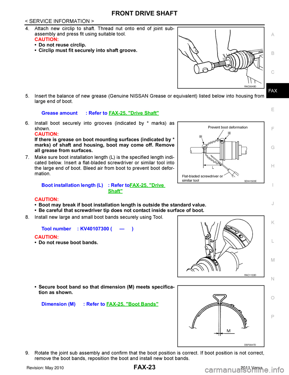
4. Attach new circlip to shaft. Thread nut onto end of joint sub- assembly and press fit using suitable tool.
CAUTION:
• Do not reuse circlip.
• Circlip must fit securely into shaft groove.
5. Insert the balance of new grease (Genuine NISSAN Grease or equivalent) listed below into housing from
large end of boot.
6. Install boot securely into grooves (indicated by * marks) as shown.
CAUTION:
If there is grease on boot mounting surfaces (indicated by *
marks) of shaft and housing, boot may come off. Remove
all grease from surfaces.
7. Make sure boot installation length (L) is the specified length indi- cated below. Insert a flat-bladed screwdriver or similar tool into
the large end of boot. Bleed air from boot to prevent boot defor-
mation.
CAUTION:
• Boot may break if boot installation le ngth is outside the standard value.
• Be careful that screwdriver tip does not contact inside surface of boot.
8. Install new large and small boot bands securely using Tool.
CAUTION:
• Do not reuse boot bands.
• Secure boot band so that dimension (M) meets specifica-tion as shown.
9. Rotate the joint sub assembly and confirm that the boot position is correct. If boot position is not correct,
remove the boot bands, reposition the boot and install new boot bands.
RAC0049D
Grease amount : Refer to FAX-25, "Drive Shaft"
Boot installation length (L) : Refer toFAX-25, "Drive
Shaft"
Tool number : KV40107300 ( — )
SDIA1505E
RAC1133D
Dimension (M) : Refer to FAX-25, "Boot Bands"
DSF0047D
Revision: May 2010 2011 Versa
Page 2667 of 3787
SERVICE DATA AND SPECIFICATIONS (SDS)FAX-25
< SERVICE INFORMATION >
CEF
G H
I
J
K L
M A
B
FA X
N
O P
SERVICE DATA AND SPECIFICATIONS (SDS)
Wheel BearingINFOID:0000000005931075
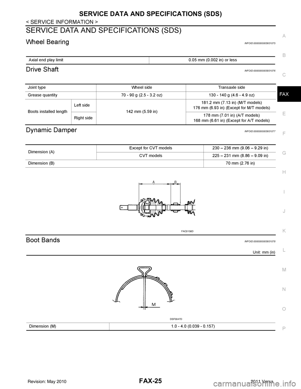
Drive ShaftINFOID:0000000005931076
Dynamic DamperINFOID:0000000005931077
Boot BandsINFOID:0000000005931078
Unit: mm (in)
Axial end play limit 0.05 mm (0.002 in) or less
Joint typeWheel sideTransaxle side
Grease quantity 70 - 90 g (2.5 - 3.2 oz)130 - 140 g (4.6 - 4.9 oz)
Boots installed length Left side
142 mm (5.59 in) 181.2 mm (7.13 in) (M/T models)
176 mm (6.93 in) (Except for M/T models)
Right side 178 mm (7.01 in) (A/T models)
168 mm (6.61 in) (Exc ept for A/T models)
Dimension (A) Except for CVT models
230 – 236 mm (9.06 – 9.29 in)
CVT models 225 – 231 mm (8.86 – 9.09 in)
Dimension (B) 70 mm (2.76 in)
FAC0156D
Dimension (M)1.0 - 4.0 (0.039 - 0.157)
DSF0047D
Revision: May 2010 2011 Versa
Page 2692 of 3787
FRONT SUSPENSION ASSEMBLYFSU-7
< SERVICE INFORMATION >
C
DF
G H
I
J
K L
M A
B
FSU
N
O P
FRONT SUSPENSION ASSEMBLY
On-Vehicle Inspection and ServiceINFOID:0000000005930898
Make sure the mounting conditions (looseness, back lash) of each component and component conditions
(wear, damage) are normal.
INSPECTION OF LOWER BALL JOINT END PLAY
1. Set front wheels in a straight-ahead position. Do not depress brake pedal.
2. Place an iron bar or similar tool between transverse link and steering knuckle.
3. Measure axial end play by prying it up and down.
CAUTION:
Be careful not to damage ball joint boot. Do not damage the installation position by applying
excessive force.
STRUT INSPECTION
Check for oil leakage, damage and replace as necessary.
Wheel Alignment InspectionINFOID:0000000005930899
PRELIMINARY INSPECTION
WARNING:
Always adjust the alignment with the vehicle on a flat surface.
NOTE:
If alignment is out of specification, inspect and replace any damaged or worn rear suspension parts before
making any adjustments.
1. Check and adjust the wheel alignment with the vehicle under unladen conditions. “Unladen conditions”
means that the fuel, coolant, and lubricant are full; and that the spare tire, jack, hand tools and mats are in
their designated positions.
2. Check the tires for incorrect air pressure and excessive wear.
3. Check the wheels for run out and damage. Refer to WT-6, "
Inspection".
4. Check the wheel bearing axial end play. Refer to FAX-6, "
On-Vehicle Inspection and Service".
5. Check the shock absorbers for leaks or damage.
6. Check each mounting point of the suspension components for any excessive looseness or damage.
7. Check each link, arm, and the suspension member for any damage.
8. Check the vehicle height. Refer to FSU-19, "
Wheelarch Height (Unladen*)".
GENERAL INFORMATION AND RECOMMENDATIONS
1. A Four-Wheel Thrust Alignment should be performed.
• This type of alignment is re commended for any NISSAN vehicle.
• The four-wheel “thrust” process helps ensure that the vehicle is properly aligned and the steering wheel
is centered.
• The alignment machine itself should be ca pable of accepting any NISSAN vehicle.
• The alignment machine should be checked to ensure that it is level.
2. Make sure the alignment machine is properly calibrated. • Your alignment machine should be regularly calibrated in order to give correct information.
• Check with the manufacturer of your specific a lignment machine for their recommended Service/Cali-
bration Schedule.
THE ALIGNMENT PROCESS
IMPORTANT: Use only the alignment specifications listed in this Service Manual. Refer to FSU-17, "Wheel
Alignment (Unladen*)".
1. When displaying the alignment settings, many alignm ent machines use “indicators”: (Green/red, plus or
minus, Go/No Go). Do NOT use these indicators.
• The alignment specifications programmed into your alignment machine that operate these indicators may not be correct.Axial end play : 0 mm (0 in)
Revision: May 2010
2011 Versa
Page 2696 of 3787
FRONT SUSPENSION ASSEMBLYFSU-11
< SERVICE INFORMATION >
C
DF
G H
I
J
K L
M A
B
FSU
N
O P
Removal and InstallationINFOID:0000000005930901
REMOVAL
1. Separate intermediate shaft from steering gear pinion shaft. Refer to PS-13, "Removal and Installation".
2. Remove front tires from vehicle using a power tool.
3. Remove wheel sensor from steering knuckle. Refer to BRC-33
.
CAUTION:
Do not pull on wheel sensor harness.
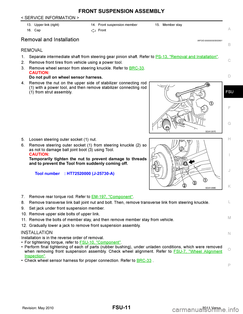
4. Remove the nut on the upper side of stabilizer connecting rod (1) with a power tool, and then remove stabilizer connecting rod
(1) from strut assembly.
5. Loosen steering outer socket (1) nut.
6. Remove steering outer socket (1) from steering knuckle (2) so as not to damage ball joint boot (3) using Tool.
CAUTION:
Temporarily tighten the nut to prevent damage to threads
and to prevent the Tool fr om suddenly coming off.
7. Remove rear torque rod. Refer to EM-197, "
Component".
8. Remove transverse link ball joint nut and bolt. Then, remove transverse link from steering knuckle.
9. Set jack under front suspension member.
10. Remove upper side bolts of upper link.
11. Remove the bolts of member stay, and then remove member stay from vehicle.
12. Gradually lower a jack to remove front suspension assembly.
INSTALLATION
Installation is in the reverse order of removal.
• For tightening torque, refer to FSU-10, "
Component".
• Perform final tightening of each of parts (rubber bushing), under unladen conditions, which were removed when removing front suspension assembly. Check wheel alignment. Refer to FSU-7, "
Wheel Alignment
Inspection".
• Check wheel sensor harness for proper connection. Refer to BRC-33
.
13. Upper link (right)14. Front suspension member15. Member stay
16. Cap Front
SGIA1297E
Tool number : HT72520000 (J-25730-A)
SGIA1298E
Revision: May 2010 2011 Versa
Page 2700 of 3787
TRANSVERSE LINKFSU-15
< SERVICE INFORMATION >
C
DF
G H
I
J
K L
M A
B
FSU
N
O P
TRANSVERSE LINK
Removal and InstallationINFOID:0000000006414956
REMOVAL
1. Remove wheel and tire. Refer to WT-7, "Adjustment".
2. Remove transverse link ball joint nut and bolt. Then, remove transverse link from steering knuckle.
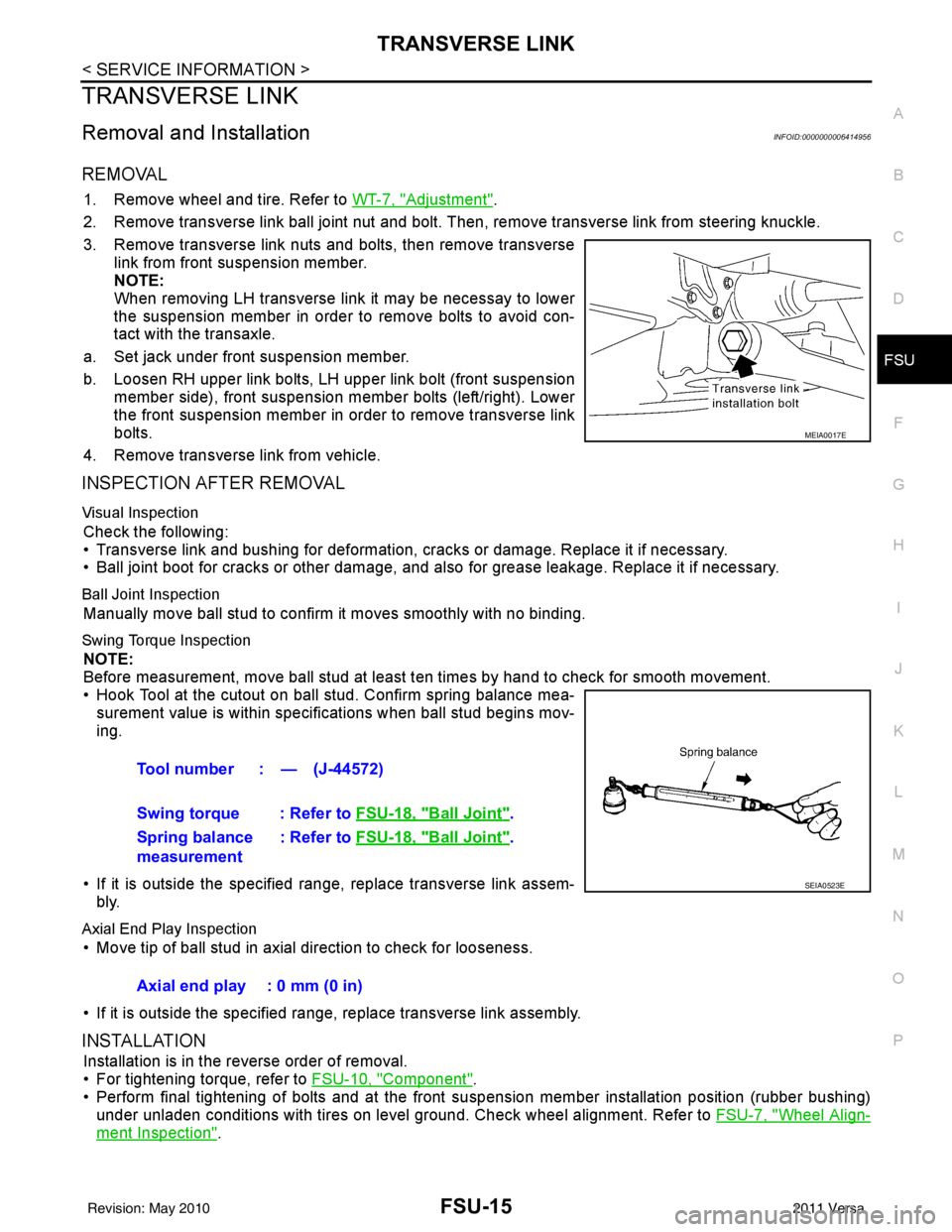
3. Remove transverse link nuts and bolts, then remove transverse link from front suspension member.
NOTE:
When removing LH transverse link it may be necessay to lower
the suspension member in order to remove bolts to avoid con-
tact with the transaxle.
a. Set jack under front suspension member.
b. Loosen RH upper link bolts, LH upper link bolt (front suspension member side), front suspension member bolts (left/right). Lower
the front suspension member in order to remove transverse link
bolts.
4. Remove transverse link from vehicle.
INSPECTION AFTER REMOVAL
Visual Inspection
Check the following:
• Transverse link and bushing for deformation, cracks or damage. Replace it if necessary.
• Ball joint boot for cracks or other damage, and also for grease leakage. Replace it if necessary.
Ball Joint Inspection
Manually move ball stud to confirm it moves smoothly with no binding.
Swing Torque Inspection
NOTE:
Before measurement, move ball stud at least ten times by hand to check for smooth movement.
• Hook Tool at the cutout on ball stud. Confirm spring balance mea- surement value is within specifications when ball stud begins mov-
ing.
• If it is outside the specified range, replace transverse link assem- bly.
Axial End Play Inspection
• Move tip of ball stud in axial direction to check for looseness.
• If it is outside the specified range, replace transverse link assembly.
INSTALLATION
Installation is in the reverse order of removal.
• For tightening torque, refer to FSU-10, "
Component".
• Perform final tightening of bolts and at the front suspension member installation position (rubber bushing)
under unladen conditions with tires on level ground. Check wheel alignment. Refer to FSU-7, "
Wheel Align-
ment Inspection".
MEIA0017E
Tool number : — (J-44572)
Swing torque : Refer to FSU-18, "
Ball Joint".
Spring balance
measurement : Refer to
FSU-18, "
Ball Joint".
SEIA0523E
Axial end play : 0 mm (0 in)
Revision: May 2010 2011 Versa
Page 2701 of 3787
FSU-16
< SERVICE INFORMATION >
STABILIZER BAR
STABILIZER BAR
Removal and InstallationINFOID:0000000005930906
REMOVAL
1. Separate intermediate shaft from steering gear pinion shaft. Refer to PS-13, "Removal and Installation".
2. Remove front tires using power tool.
3. Remove the nut on the lower side of stabilizer connecting rod using power tool, and then remove stabilizer connecting rod from stabilizer bar.
4. If necessary remove stabilize connecting rod upper nut using power tool. Separate stabilizer connecting rod and strut.
5. Loose steering outer socket (1) nut.
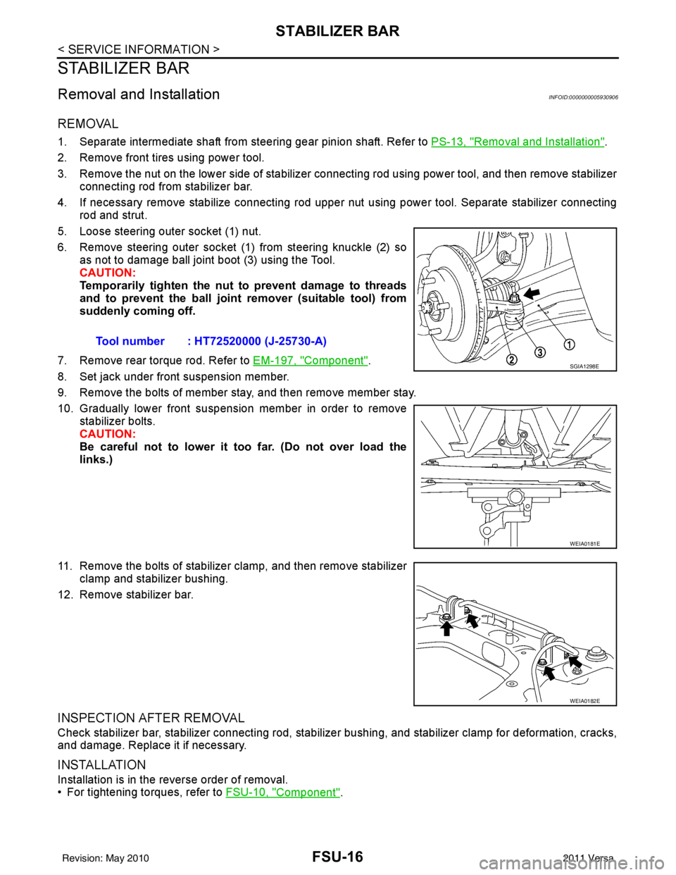
6. Remove steering outer socket (1) from steering knuckle (2) so as not to damage ball joint boot (3) using the Tool.
CAUTION:
Temporarily tighten the nut to prevent damage to threads
and to prevent the ball joint remover (suitable tool) from
suddenly coming off.
7. Remove rear torque rod. Refer to EM-197, "
Component".
8. Set jack under front suspension member.
9. Remove the bolts of member stay, and then remove member stay.
10. Gradually lower front suspension member in order to remove stabilizer bolts.
CAUTION:
Be careful not to lower it too far. (Do not over load the
links.)
11. Remove the bolts of stabilizer clamp, and then remove stabilizer clamp and stabilizer bushing.
12. Remove stabilizer bar.
INSPECTION AFTER REMOVAL
Check stabilizer bar, stabilizer connecting rod, stabilizer bushing, and stabilizer clamp for deformation, cracks,
and damage. Replace it if necessary.
INSTALLATION
Installation is in the reverse order of removal.
• For tightening torques, refer to FSU-10, "
Component".
Tool number : HT72520000 (J-25730-A)
SGIA1298E
WEIA0181E
WEIA0182E
Revision: May 2010
2011 Versa
Page 2713 of 3787
HOW TO USE THIS MANUALGI-9
< SERVICE INFORMATION >
C
DE
F
G H
I
J
K L
M B
GI
N
O P
SYMBOLS
How to Follow Trouble DiagnosisINFOID:0000000005929724
DESCRIPTION
NOTICE:
Trouble diagnoses indicate work procedures required to diagnose problems effectively. Observe the following
instructions before diagnosing.
1. Before performing trouble diagno ses, read the “Preliminary Check” , the “Symptom Chart” or the
“Work Flow”.
2. After repairs, re-check that the prob lem has been completely eliminated.
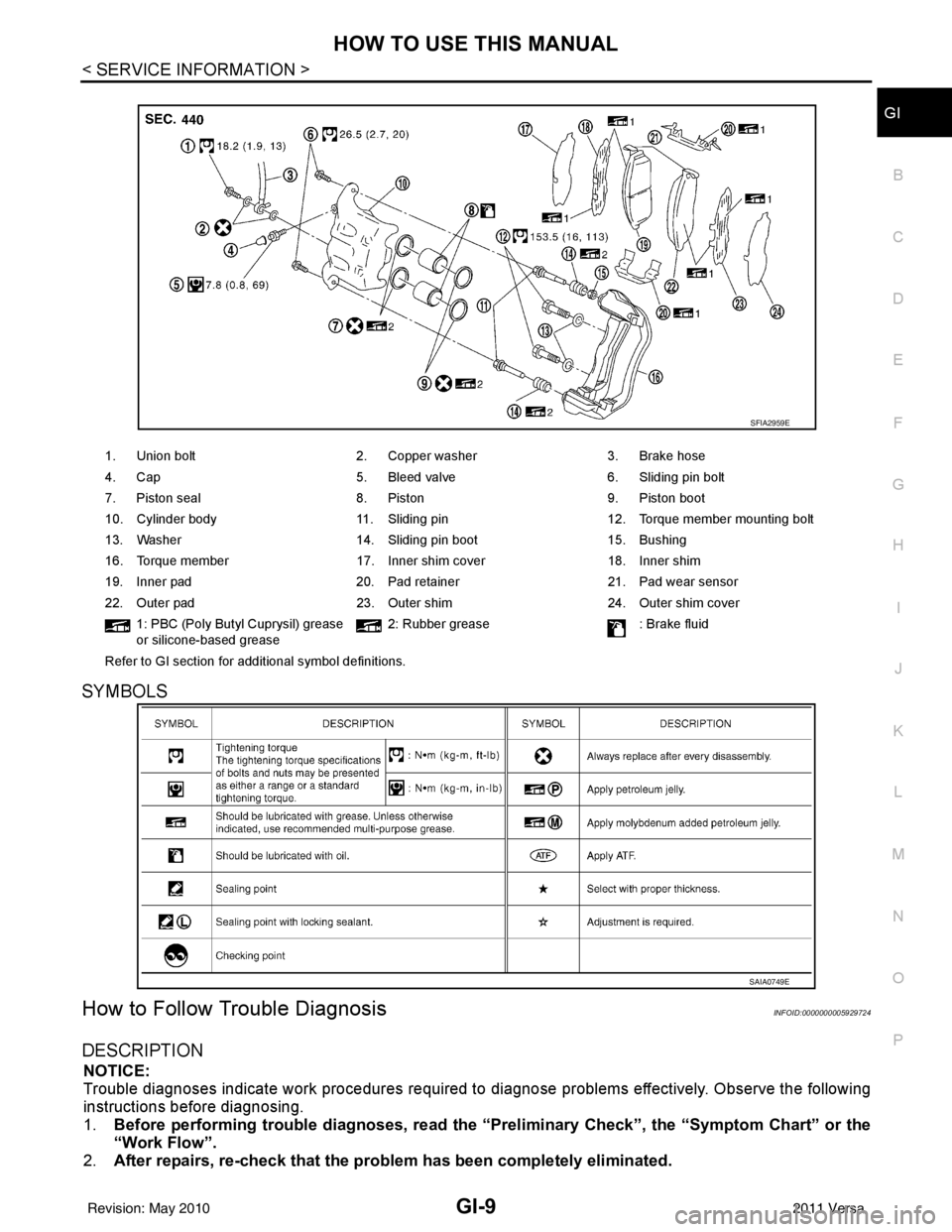
1. Union bolt 2. Copper washer3. Brake hose
4. Cap 5. Bleed valve6. Sliding pin bolt
7. Piston seal 8. Piston9. Piston boot
10. Cylinder body 11. Sliding pin12. Torque member mounting bolt
13. Washer 14. Sliding pin boot15. Bushing
16. Torque member 17. Inner shim cover18. Inner shim
19. Inner pad 20. Pad retainer21. Pad wear sensor
22. Outer pad 23. Outer shim24. Outer shim cover
1: PBC (Poly Butyl Cuprysil) grease
or silicone-based grease 2: Rubber grease
: Brake fluid
Refer to GI section for additional symbol definitions.
SFIA2959E
SAIA0749E
Revision: May 2010 2011 Versa