Page 2833 of 3787

IP-12
< ON-VEHICLE REPAIR >
INSTRUMENT PANEL ASSEMBLY
Removal and Installation
INFOID:0000000005929593
CAUTION:
• Disconnect both the negative and positive battery terminals, then wait at least three minutes.
• Never tamper with or force air bag lid open, as this may adversely affect air bag performance.
• Be careful not to scratch pad and other parts.
INSTRUMENT PANEL ASSEMBLY
Removal
1. Disconnect both the negative and positive battery terminals, then wait at least three minutes.
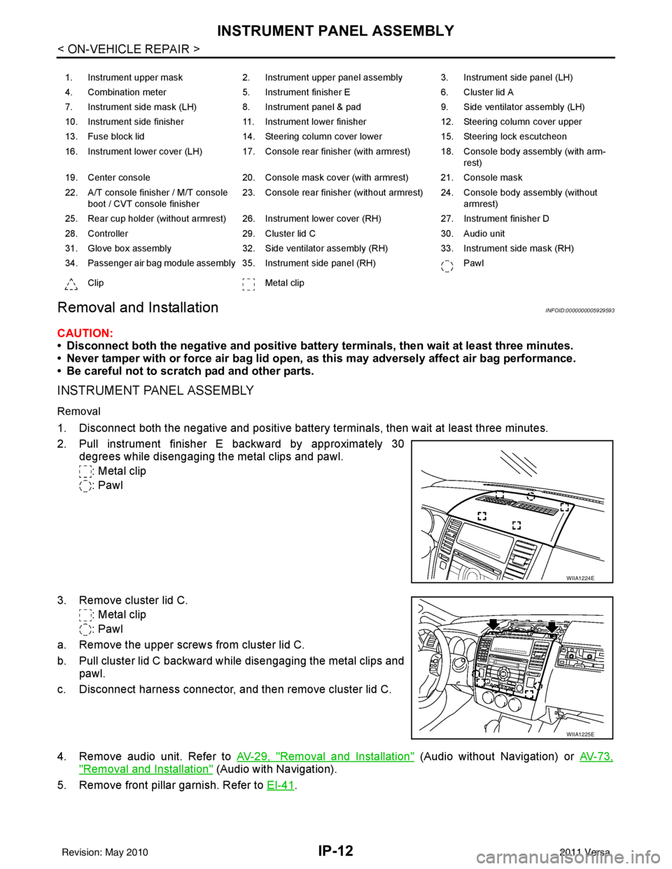
2. Pull instrument finisher E backward by approximately 30
degrees while disengaging the metal clips and pawl.
: Metal clip
: Pawl
3. Remove cluster lid C. : Metal clip
: Pawl
a. Remove the upper screws from cluster lid C.
b. Pull cluster lid C backward while disengaging the metal clips and pawl.
c. Disconnect harness connector, and then remove cluster lid C.
4. Remove audio unit. Refer to AV-29, "
Removal and Installation" (Audio without Navigation) or AV-73,
"Removal and Installation" (Audio with Navigation).
5. Remove front pillar garnish. Refer to EI-41
.
1. Instrument upper mask 2. Instrument upper panel assembly 3. Instrument side panel (LH)
4. Combination meter 5. Instrument finisher E 6. Cluster lid A
7. Instrument side mask (LH) 8. Instrument panel & pad 9. Side ventilator assembly (LH)
10. Instrument side finisher 11. Instrument lower finisher 12. Steering column cover upper
13. Fuse block lid 14. Steering column cover lower 15. Steering lock escutcheon
16. Instrument lower cover (LH) 17. Console rear finisher (with armrest) 18. Console body assembly (with arm- rest)
19. Center console 20. Console mask cover (with armrest) 21. Console mask
22. A/T console finisher / M/T console boot / CVT console finisher 23. Console rear finisher (without armrest) 24. Console body assembly (without
armrest)
25. Rear cup holder (without armrest) 26. Instrument lower cover (RH) 27. Instrument finisher D
28. Controller 29. Cluster lid C 30. Audio unit
31. Glove box assembly 32. Side ventilator assembly (RH) 33. Instrument side mask (RH)
34. Passenger air bag module assembly 35. Instrument side panel (RH) Pawl
Clip Metal clip
WIIA1224E
WIIA1225E
Revision: May 2010 2011 Versa
Page 2843 of 3787

IP-22
< ON-VEHICLE REPAIR >
INSTRUMENT PANEL ASSEMBLY
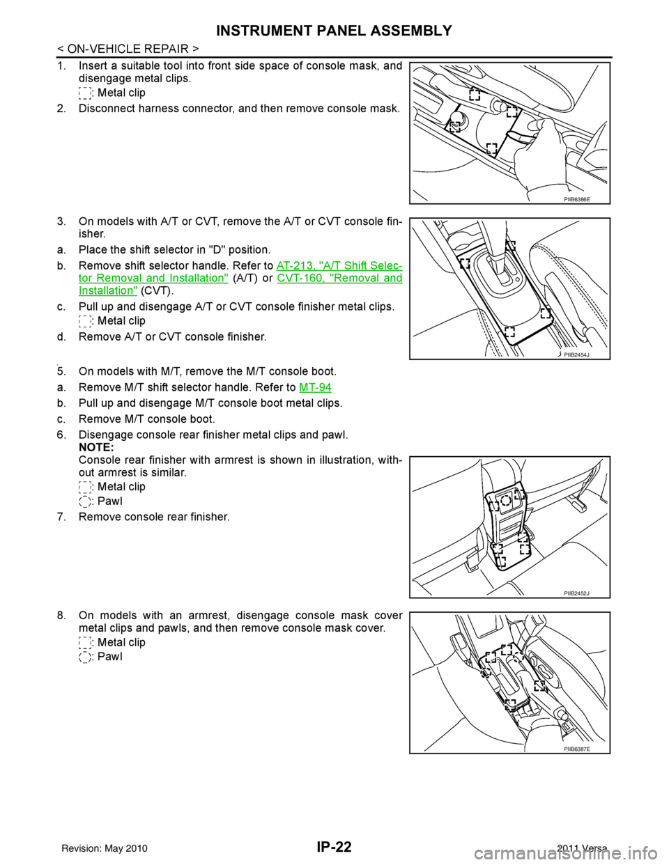
1. Insert a suitable tool into front side space of console mask, anddisengage metal clips.
: Metal clip
2. Disconnect harness connector, and then remove console mask.
3. On models with A/T or CVT, remo ve the A/T or CVT console fin-
isher.
a. Place the shift selector in "D" position.
b. Remove shift selector handle. Refer to AT-213, "
A/T Shift Selec-
tor Removal and Installation" (A/T) or CVT-160, "Removal and
Installation" (CVT).
c. Pull up and disengage A/T or CVT console finisher metal clips. : Metal clip
d. Remove A/T or CVT console finisher.
4.5. On models with M/T, remove the M/T console boot.
a. Remove M/T shift selector handle. Refer to MT-94
b. Pull up and disengage M/T console boot metal clips.
c. Remove M/T console boot.
6. Disengage console rear finisher metal clips and pawl.
NOTE:
Console rear finisher with armrest is shown in illustration, with-
out armrest is similar.
: Metal clip
: Pawl
7. Remove console rear finisher.
8. On models with an armrest, disengage console mask cover metal clips and pawls, and then remove console mask cover.
: Metal clip
: Pawl
PIIB6386E
PIIB2454J
PIIB2452J
PIIB6387E
Revision: May 2010 2011 Versa
Page 3182 of 3787

PERIODIC MAINTENANCEMA-11
< SERVICE INFORMATION >
C
DE
F
G H
I
J
K
M A
B
MA
N
O P
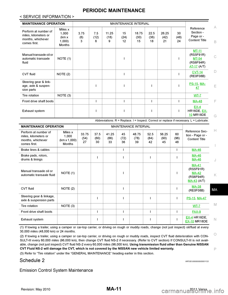
Abbreviations: R = Replace. I = Inspect. Corr ect or replace if necessary. L = Lubricate.
(1) If towing a trailer, using a camper or car-top carrier, or driving on rough or muddy roads, change (not just inspect) oil/f luid at every
30,000 miles (48,000 km) or 24 months.
(2) If towing a trailer, using a camper or car-top carrier, or driving on rough or muddy roads, inspect CVT fluid deterioration with CON-
SULT-III every 60,000 miles (96,000 km), then change CVT fluid NS -2 if necessary. (Refer to CVT section) If CONSULT-III is not avail-
able, change (not just inspect) CVT fluid NS-2 every 60,000 miles (96,000 km). Using transmission fluid other than Genuine NISSAN
CVT Fluid NS-2 will damage the CVT, which is not covered by the NISSAN new vehicle limited warranty.
(3) Refer to “Tire rotation” under the “GENERAL MAINTENANCE” heading earlier in this section.
Schedule 2INFOID:0000000005931133
Emission Control System Maintenance
Manual transaxle oil or
automatic transaxle
fluidNOTE (1)
IIMT-11
(RS5F91R) MT-54
(RS6F94R)
AT- 1 7
(A/T)
CVT fluid NOTE (2) IICVT-14
(RE0F08B)
Steering gear & link-
age, axle & suspen-
sion parts IIII
PS-15
, MA-
47
Tire rotation
NOTE (3) WT-7
Front drive shaft bootsIIIIMA-48
Exhaust system IIIIEX-4
HR16DE, EX-
10 MR18DE
MAINTENANCE OPERATION
MAINTENANCE INTERVAL
Reference Section -
Page or -
Content Title
Perform at number of
miles, kilometers or
months, whichever
comes first. Miles x
1,000
(km x
1,000)
Months 3.75
(6)3 7.5
(12) 6 11 . 2 5
(18) 9 15
(24) 12 18.75
(30)15 22.5
(36) 18 26.25
(42)21 30
(48) 24
MAINTENANCE OPERATION MAINTENANCE INTERVAL
Reference Sec-tion - Page or - Content Title
Perform at number of
miles, kilometers or
months, whichever
comes first. Miles x
1,000
(km x 1,000)
Months 33.75
(54)27 37.5
(60) 30 41.25
(66)33 45
(72) 36 48.75
(78)39 52.5
(84) 42 56.25
(90)45 60
(96) 48
Brake lines & cables IIMA-46
Brake pads, rotors,
drums & linings II I I
MA-46
MA-46
Manual transaxle oil or
automatic transaxle fluidNOTE (1)
IIMA-41
(RS5F91R)
MA-42
(RS6F94R)
MA-43
(A/T)
CVT fluid NOTE (2) IIMA-38
(RE0F08B)
Steering gear & linkage,
axle & suspension parts II I I
PS-15
, MA-47
Tire rotationNOTE (3) WT-7
Front drive shaft bootsII IIFAX-9
Exhaust system II IIEX-4 HR16DE,
EX-10
MR18DE
Revision: May 2010 2011 Versa
Page 3184 of 3787
PERIODIC MAINTENANCEMA-13
< SERVICE INFORMATION >
C
DE
F
G H
I
J
K
M A
B
MA
N
O P
(1) Using transmission fluid other than Genuine NISSAN CVT Flui d NS-2 will damage the CVT, which is not covered by the
NISSAN new vehicle limited warranty .
(2) Refer to “Tire rotation” under the “GENERAL MAINTENANCE” heading earlier in this section.
Front drive shaft boots I I I I
MA-48
Exhaust systemIIEX-4 HR16DE,
EX-10
MR18DE
MAINTENANCE OPERATION
MAINTENANCE INTERVAL
Reference Sec-
tion - Page or -
Content Title
Perform at number of miles, kilo-
meters or months, whichever
comes first. Miles x 1,000
(km x 1,000)
Months 7.5
(12)
6 15
(24)
12 22.5
(36)
18 30
(48)
24 37.5
(60)
30 45
(72)
36 52.5
(84)
42 60
(96)
48
Revision: May 2010 2011 Versa
Page 3219 of 3787
MA-48
< SERVICE INFORMATION >
CHASSIS AND BODY MAINTENANCE
DRIVE SHAFT
DRIVE SHAFT : Drive ShaftINFOID:0000000005931185
Check boot and drive shaft for cracks, wear, damage and grease
leakage.
LOCKS, HINGES AND HOOD LATCH
SFA392B
SDIA1190J
Revision: May 2010 2011 Versa
Page 3236 of 3787
CONTROL LINKAGEMT-15
< SERVICE INFORMATION > [RS5F91R]
D
E
F
G H
I
J
K L
M A
B
MT
N
O P
• Move the shift selector to the neutral position.
• Securely assemble each of the cables to each select lever of control shaft, mounting bracket, and the M/T
shift selector assembly.
• Be careful about the installation direction, and push shift selector handle onto shift selector.
CAUTION:
Do not reuse shift selector handle.
• Make sure that the front/rear claws (1) of M/T shift selector assem- bly are in contact with flange of the floor (2).
InspectionINFOID:0000000005929669
Inspect the following items:
• When shift selector is moved to 1st-2nd side and 5th-reve rse side, confirm shift selector returns to neutral
position smoothly.
• When the shift selector is shifted to each position, make sure there is no binding or disconnection in each
boot.
PCIB1509E
PCIB1510E
Revision: May 2010 2011 Versa
Page 3280 of 3787
![NISSAN LATIO 2011 Service Repair Manual CONTROL LINKAGEMT-59
< SERVICE INFORMATION > [RS6F94R]
D
E
F
G H
I
J
K L
M A
B
MT
N
O P
b. Pull the release button (1) of select cable (2) and then remove it from control shaft select lever (3).
5. Mo NISSAN LATIO 2011 Service Repair Manual CONTROL LINKAGEMT-59
< SERVICE INFORMATION > [RS6F94R]
D
E
F
G H
I
J
K L
M A
B
MT
N
O P
b. Pull the release button (1) of select cable (2) and then remove it from control shaft select lever (3).
5. Mo](/manual-img/5/57357/w960_57357-3279.png)
CONTROL LINKAGEMT-59
< SERVICE INFORMATION > [RS6F94R]
D
E
F
G H
I
J
K L
M A
B
MT
N
O P
b. Pull the release button (1) of select cable (2) and then remove it from control shaft select lever (3).
5. Move shift selector to neutral position.
6. Remove shift selector handle.
7. Remove center console assembly. Refer to IP-12, "
Removal and
Installation".
8. Remove M/T shift selector assembly bolts.
9. Remove exhaust front tube, cent er muffler and heat plate. Refer
to EX-10, "
Removal and Installation".
10. Remove cable support bracket.
11. Remove select cable and shift selector cable from cable bracket.
12. Remove M/T shift selector assembly from the vehicle.
INSTALLATION
Installation is in the reverse order of removal.
NOTE:
Self tapping bolts are used to attach cables to the clutch housing.
• Securely assemble each cable and lever of control shaft.
• Be careful about the installation direction, and push shift selector handle onto shift selector.
CAUTION:
Do not reuse shift selector handle.
• Make sure that the front/rear claws (1) of M/T shift selector assem- bly are in contact with flange of the floor (2).
• When shift selector is selected to 1st-2nd side and 5th-6th side, confirm shift lever returns to neutral position smoothly.
• When shift selector is shifted to each position, make sure there is
no binding or disconnection in each boot.
• Move stopper (1) to lock position when installing the shift cable onto the control shaft shift lever.
WCIA0606E
SCIA7630E
PCIB1510E
SCIA7846E
Revision: May 2010 2011 Versa
Page 3498 of 3787
PS-4
< SERVICE INFORMATION >
PREPARATION
PREPARATION
Special Service ToolINFOID:0000000005929630
The actual shapes of Kent-Moore tools may differ from thos e of special tools illustrated here.
Commercial Service ToolINFOID:0000000005929631
Tool number
(Kent-Moore No.)
Tool name Description
ST3127S000
(J-25742-1)
Preload gauge
(J-25765-A)
1. GG91030000
Torque wrench
2. HT62940000
(—)
Socket adapter (1/2")
3. HT62900000
(—)
Socket adapter (3/8") Inspecting rotating torque for steering column
assembly and pinion assembly
KV40107300
(—)
Boot Band crimping tool Installing boot bands
KV48103400
(—)
Preload adapter Inspecting of rotating torque for pinion assem-
bly
—
(J-44372)
Pull gauge Measuring steering wheel turning force and
ball joint swinging force.
S-NT541
ZZA1229D
ZZA0824D
LST024
Tool number
Tool name
Description
Power tool Removing nuts and bolts
PBIC0190E
Revision: May 2010 2011 Versa