REAR WIPER AND WASHER SYSTEMWW-27
< SERVICE INFORMATION >
C
DE
F
G H
I
J
L
M A
B
WW
N
O P
REAR WIPER AND WASHER SYSTEM
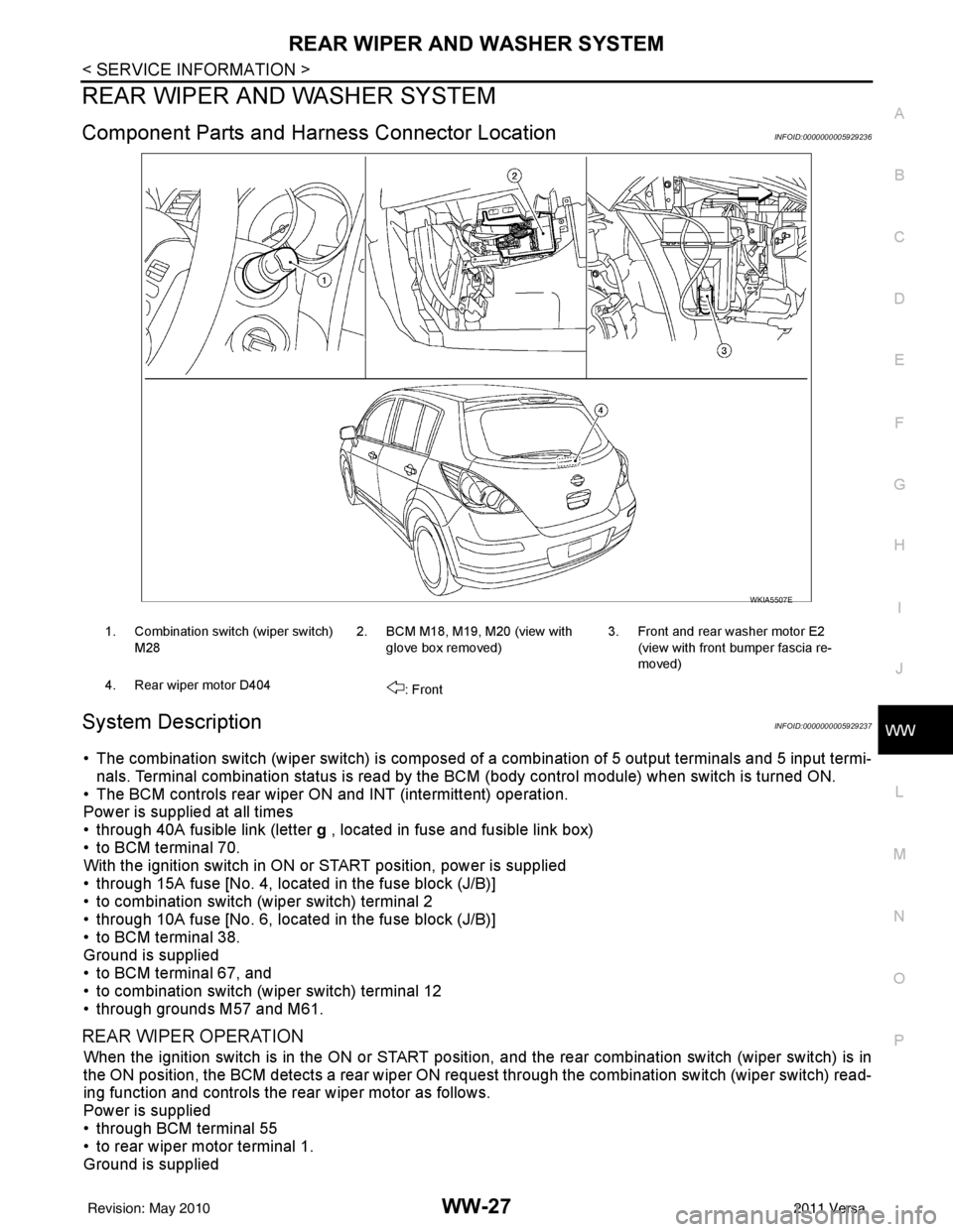
Component Parts and Har ness Connector LocationINFOID:0000000005929236
System DescriptionINFOID:0000000005929237
• The combination switch (wiper switch) is composed of a combination of 5 output terminals and 5 input termi-
nals. Terminal combination status is read by the BCM (body control module) when switch is turned ON.
• The BCM controls rear wiper ON and INT (intermittent) operation.
Power is supplied at all times
• through 40A fusible link (letter g , located in fuse and fusible link box)
• to BCM terminal 70.
With the ignition switch in ON or START position, power is supplied
• through 15A fuse [No. 4, located in the fuse block (J/B)]
• to combination switch (wiper switch) terminal 2
• through 10A fuse [No. 6, located in the fuse block (J/B)]
• to BCM terminal 38.
Ground is supplied
• to BCM terminal 67, and
• to combination switch (wiper switch) terminal 12
• through grounds M57 and M61.
REAR WIPER OPERATION
When the ignition switch is in the ON or START position, and the rear combination switch (wiper switch) is in
the ON position, the BCM detects a rear wiper ON r equest through the combination switch (wiper switch) read-
ing function and controls the rear wiper motor as follows.
Power is supplied
• through BCM terminal 55
• to rear wiper motor terminal 1.
Ground is supplied
WKIA5507E
1. Combination switch (wiper switch)
M28 2. BCM M18, M19, M20 (view with
glove box removed) 3. Front and rear washer motor E2
(view with front bumper fascia re-
moved)
4. Rear wiper motor D404 : Front
Revision: May 2010 2011 Versa