2011 NISSAN LATIO transmission
[x] Cancel search: transmissionPage 1206 of 3787
![NISSAN LATIO 2011 Service Repair Manual TROUBLE DIAGNOSIS FOR SYMPTOMSCVT-151
< SERVICE INFORMATION > [RE0F08B]
D
E
F
G H
I
J
K L
M A
B
CVT
N
O P
Vehicle Speed Does Not Change in "D" PositionINFOID:0000000005928955
SYMPTOM:
Vehicle speed d NISSAN LATIO 2011 Service Repair Manual TROUBLE DIAGNOSIS FOR SYMPTOMSCVT-151
< SERVICE INFORMATION > [RE0F08B]
D
E
F
G H
I
J
K L
M A
B
CVT
N
O P
Vehicle Speed Does Not Change in "D" PositionINFOID:0000000005928955
SYMPTOM:
Vehicle speed d](/manual-img/5/57357/w960_57357-1205.png)
TROUBLE DIAGNOSIS FOR SYMPTOMSCVT-151
< SERVICE INFORMATION > [RE0F08B]
D
E
F
G H
I
J
K L
M A
B
CVT
N
O P
Vehicle Speed Does Not Change in "D" PositionINFOID:0000000005928955
SYMPTOM:
Vehicle speed does not change in “D” position while the cruise test.
DIAGNOSTIC PROCEDURE
1.CHECK SELF-DIAGNOSTIC RESULTS
Perform self-diagnosis check. Refer to CVT-48, "
CONSULT-III Function (TRANSMISSION)" .
Is any malfunction detected by self-diagnosis?
YES >> Check the malfunctioning system. Refer to CVT-48, "CONSULT-III Function (TRANSMISSION)" .
NO >> GO TO 2.
2.CHECK CVT POSITION
Check CVT position. Refer to CVT-164, "
Checking of CVT Position"
OK or NG
OK >> GO TO 3.
NG >> Adjust CVT position. Refer to CVT-164, "
Adjustment of CVT Position" .
3.CHECK CVT FLUID LEVEL
Check CVT fluid level. Refer to CVT-14, "
Checking CVT Fluid" .
OK or NG
OK >> GO TO 4.
NG >> Refill CVT fluid.
4.CHECK LINE PRESSURE
Check line pressure at idle. Refer to CVT-37, "
Inspections before Trouble Diagnosis" .
OK or NG
OK >> GO TO 5.
NG >> Check the malfunctioning item. Refer to CVT-37, "
Inspections before Trouble Diagnosis" .
5.CHECK STALL REVOLUTION
Check stall revolution. Refer to CVT-37, "
Inspections before Trouble Diagnosis" .
OK or NG
OK >> GO TO 6.
NG >> Check the malfunctioning item. Refer to CVT-37, "
Inspections before Trouble Diagnosis" .
6.CHECK SYMPTOM
Check again. Refer to CVT-43, "
Cruise Test" .
OK or NG
OK >> INSPECTION END
NG >> GO TO 7.
7.CHECK TCM
1. Check TCM input/output signals. Refer to CVT-46, "
TCM Terminal and Reference Value" .
2. If NG, re-check TCM pin terminals for dam age or loose connection with harness connector.
OK or NG
OK >> Replace the transaxle assembly. Refer to CVT-180, "Removal and Installation" .
NG >> Repair or replace damaged parts.
Vehicle Does Not Decelerate by Engine BrakeINFOID:0000000005928956
SYMPTOM:
Engine brake does not operate when releasing the accelerator pedal while the cruise test.
DIAGNOSTIC PROCEDURE
1.CHECK SELF-DIAGNOSTIC RESULTS
Revision: May 2010 2011 Versa
Page 1207 of 3787
![NISSAN LATIO 2011 Service Repair Manual CVT-152
< SERVICE INFORMATION >[RE0F08B]
TROUBLE DIAGNOSIS FOR SYMPTOMS
Perform self-diagnosis check. Refer to
CVT-48, "CONSULT-III Function (TRANSMISSION)" .
Is any malfunction detec ted by self-dia NISSAN LATIO 2011 Service Repair Manual CVT-152
< SERVICE INFORMATION >[RE0F08B]
TROUBLE DIAGNOSIS FOR SYMPTOMS
Perform self-diagnosis check. Refer to
CVT-48, "CONSULT-III Function (TRANSMISSION)" .
Is any malfunction detec ted by self-dia](/manual-img/5/57357/w960_57357-1206.png)
CVT-152
< SERVICE INFORMATION >[RE0F08B]
TROUBLE DIAGNOSIS FOR SYMPTOMS
Perform self-diagnosis check. Refer to
CVT-48, "CONSULT-III Function (TRANSMISSION)" .
Is any malfunction detec ted by self-diagnosis?
YES >> Check the malfunctioning system. Refer to CVT-48, "CONSULT-III Function (TRANSMISSION)" .
NO >> GO TO 2.
2.CHECK CVT POSITION
Check CVT position. Refer to CVT-164, "
Checking of CVT Position"
OK or NG
OK >> GO TO 3.
NG >> Adjust CVT position. Refer to CVT-164, "
Adjustment of CVT Position" .
3.CHECK CVT FLUID LEVEL
Check CVT fluid level. Refer to CVT-14, "
Checking CVT Fluid" .
OK or NG
OK >> GO TO 4.
NG >> Refill CVT fluid.
4.CHECK LINE PRESSURE
Check line pressure at idle. Refer to CVT-37, "
Inspections before Trouble Diagnosis" .
OK or NG
OK >> GO TO 5.
NG >> Check the malfunctioning item. Refer to CVT-37, "
Inspections before Trouble Diagnosis" .
5.CHECK SYMPTOM
Check again. Refer to CVT-43, "
Cruise Test" .
OK or NG
OK >> INSPECTION END
NG >> GO TO 6.
6.CHECK TCM
1. Check TCM input/output signals. Refer to CVT-46, "
TCM Terminal and Reference Value" .
2. If NG, re-check TCM pin terminals for damage or loose connection with harness connector.
OK or NG
OK >> Replace the transaxle assembly. Refer to CVT-180, "Removal and Installation" .
NG >> Repair or replace damaged parts.
Revision: May 2010 2011 Versa
Page 1236 of 3787
![NISSAN LATIO 2011 Service Repair Manual TRANSAXLE ASSEMBLYCVT-181
< SERVICE INFORMATION > [RE0F08B]
D
E
F
G H
I
J
K L
M A
B
CVT
N
O P
2. Disconnect the primary speed sensor (A) and the secondary
speed sensor connector (B) and CVT unit conn NISSAN LATIO 2011 Service Repair Manual TRANSAXLE ASSEMBLYCVT-181
< SERVICE INFORMATION > [RE0F08B]
D
E
F
G H
I
J
K L
M A
B
CVT
N
O P
2. Disconnect the primary speed sensor (A) and the secondary
speed sensor connector (B) and CVT unit conn](/manual-img/5/57357/w960_57357-1235.png)
TRANSAXLE ASSEMBLYCVT-181
< SERVICE INFORMATION > [RE0F08B]
D
E
F
G H
I
J
K L
M A
B
CVT
N
O P
2. Disconnect the primary speed sensor (A) and the secondary
speed sensor connector (B) and CVT unit connector (C). Refer
to CVT-9, "
Removal and Installation Procedure for CVT Unit
Connector".
3. Remove the harness from the transaxle.
4. Remove the four drive plate to torque converter nuts. NOTE:
Rotate the crankshaft clockwise as viewed from front of engine
for access to drive plate to torque converter nuts.
5. Put matching marks on the drive plate and torque converter alignment stud. CAUTION:
For matching marks, use paint. Never dama ge the drive plate or torque converter.
6. Remove the transaxle to engine and engine to transaxle bolts.
7. Separate the transaxle from the engine.
8. If necessary, remove the following from the transaxle: • CVT fluid charging pipe
• Engine mounting bracket (LH)
• Fluid cooler tubes
• Air breather hose
• Any necessary brackets
INSTALLATION
Installation is in the reverse order of removal.
CAUTION:
• When replacing an engine or transmission you must make sure any dowels are installed correctlyduring re-assembly.
• Improper alignment caused by missing dowels may cause vibration, oil leaks or breakage of drive train components.
• Do not reuse O-rings and copper washers.
• When turning crankshaft, turn it clockwise as viewed from the front of the engine.
• When tightening the nuts for the torque converter while securing the crankshaft pulley bolt, be sure
to confirm the tightening torque of the crankshaft pulley bolt. Refer to EM-159
.
• After converter is installed to drive plate, ro tate crankshaft several turns to check that transaxle
rotates freely without binding.
AWDIA0661GB
WCIA0616E
Revision: May 2010 2011 Versa
Page 1238 of 3787
![NISSAN LATIO 2011 Service Repair Manual SERVICE DATA AND SPECIFICATIONS (SDS)CVT-183
< SERVICE INFORMATION > [RE0F08B]
D
E
F
G H
I
J
K L
M A
B
CVT
N
O P
SERVICE DATA AND SPECIFICATIONS (SDS)
General SpecificationINFOID:0000000005928977
*: T NISSAN LATIO 2011 Service Repair Manual SERVICE DATA AND SPECIFICATIONS (SDS)CVT-183
< SERVICE INFORMATION > [RE0F08B]
D
E
F
G H
I
J
K L
M A
B
CVT
N
O P
SERVICE DATA AND SPECIFICATIONS (SDS)
General SpecificationINFOID:0000000005928977
*: T](/manual-img/5/57357/w960_57357-1237.png)
SERVICE DATA AND SPECIFICATIONS (SDS)CVT-183
< SERVICE INFORMATION > [RE0F08B]
D
E
F
G H
I
J
K L
M A
B
CVT
N
O P
SERVICE DATA AND SPECIFICATIONS (SDS)
General SpecificationINFOID:0000000005928977
*: The fluid capacity is the reference value. Check the fluid level with CVT fluid level gauge.
Vehicle Speed When Shifting GearsINFOID:0000000005928978
Numerical value data are reference values.
CAUTION:
Lock-up clutch is engaged when vehi cle speed is approximately 18 km/h (11 MPH) to 90 km/h (56 MPH).
Stall SpeedINFOID:0000000005928979
Line PressureINFOID:0000000005928980
Applied model MR18DE engine
CVT model RE0F08B
CVT assembly Model code number 1XC6B
Transmission gear ratio “D” position
Variable
Reverse 2.689
Final drive 5.473
Recommended fluid NISSAN CVT Fluid NS-2
Fluid capacity 6.9 liter (7-1/4 US qt, 6-1/8 Imp qt)*
CAUTION:
• Use only Genuine NISSAN CVT Fluid NS-2. Do not mix with other fluid.
• Using CVT fluid other than Genuine NISSAN CVT Fluid NS-2 will deteriorate in driveability and CVT durability, and may dam- age the CVT, which is not covered by the warranty.
Engine type Throttle position Shift pattern Engine speed (rpm)
At 40 km/h (25 MPH) At 60 km/h (37 MPH)
MR18DE 8/8
“D” position
Overdrive-off mode
“L” position 3,600 - 4,500
4,400 - 5,300
2/8 “D” position
1,300 - 3,100 1,400 - 3,500
Overdrive-off mode 2,200 - 3,000 2,800 - 3,600
“L” position 3,100 - 4,000 3,800 - 4,700
Stall speed 2,600 - 3,150 rpm
Engine speed Line pressure kPa (kg/cm
2 , psi)
“R”, “D” and “L” positions
At idle 650 (6.63, 94.3)
At stall 4,250 (43.35, 616.3)
Revision: May 2010 2011 Versa
Page 1250 of 3787

COMBINATION METERSDI-11
< SERVICE INFORMATION >
C
DE
F
G H
I
J
L
M A
B
DI
N
O P
Self-Diagnosis Mode of Combination MeterINFOID:0000000005929166
SELF-DIAGNOSIS MODE FUNCTION
• Self-diagnosis can check for continuity between meter control circuit and each meter (speedometer, tachom- eter and fuel gauge).
• Self-diagnosis can check for odo/trip meter and A/T indi cator (with A/T) or CVT indicator (with CVT) seg-
ment, low-fuel level warning lamp, low water temperature indicator lamp, and high water temperature warn-
ing lamp.
OPERATION PROCEDURE
1. Turn the ignition switch ON, and switch the odo/trip meter to “trip A” or “trip B”. NOTE:
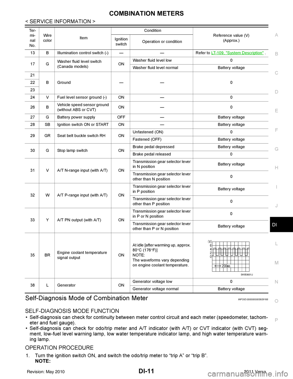
13 B Illumination control switch (-) — —Refer to LT- 1 0 9 , "System Description" .
17 G Washer fluid level switch
(Canada models)
ONWasher fluid level low
0
Washer fluid level normal Battery voltage
21 BGround —— 0
22
23
24 V Fuel level sensor ground (-) ON —0
26 B Vehicle speed sensor ground
(without ABS or CVT) ON
— 0
27 G Battery power supply OFF— Battery voltage
28 SB Ignition switch ON or START ON —Battery voltage
29 GR Seat belt buckle switch RH ON Unfastened (ON)
0
Fastened (OFF) Battery voltage
30 G Stop lamp switch ONBrake pedal depressed
Battery voltage
Brake pedal released 0
31 V A/T N-range input (with A/T) ON Transmission gear selector lever
in N position
Battery voltage
Transmission gear selector lever
other than N position 0
32 W A/T P-range input (with A/T) ON Transmission gear selector lever
in P position
Battery voltage
Transmission gear selector lever
other than P position 0
33 Y A/T PN output (with A/T) ON Transmission gear selector lever
in P or N position
0
Transmission gear selector lever
other than P or N position Battery voltage
35 BR Engine coolant temperature
signal output
ONAt idle [after warming up, approx.
80
°C (176 °F)]
NOTE:
The waveforms vary depending
on engine coolant temperature.
38 L Generator ONGenerator voltage low
0
Generator voltage no rmal Battery voltage
Te r -
mi-
nal
No. Wire
color Item Condition
Reference value (V)
(Approx.)
Ignition
switch Operation or condition
SKIB3651J
Revision: May 2010
2011 Versa
Page 1256 of 3787

COMBINATION METERSDI-17
< SERVICE INFORMATION >
C
DE
F
G H
I
J
L
M A
B
DI
N
O P
OK or NG
OK >> Check harness or connector between combination meter and vehicle speed sensor.
NG >> Replace vehicle speed sensor.
WITH CVT, WITHOUT ABS
1.CHECK COMBINATION METER INPUT SIGNAL
1. Start engine and select “M ETER/M&A” on CONSULT-III.
2. Using “SPEED METER” on “DATA MONITOR”, comp are the value of “DATA MONITOR” with speedome-
ter pointer of combination meter.
OK or NG
OK >> Perform TCM self-diagnosis. Refer to CVT-48, "CONSULT-III Function (TRANSMISSION)" .
NG >> Replace combination meter. Refer to IP-12, "
Removal and Installation" .
Engine Speed Signal InspectionINFOID:0000000005929172
Symptom: Improper tachometer indication.
1.CHECK COMBINATION METER INPUT SIGNAL
1. Start engine and select “M ETER/M&A” on CONSULT-III.
2. Using “TACHO METER” on “DATA MONITOR”, compare the value of “DATA MONITOR” with tachometer pointer of combination meter.
OK or NG
OK >> Perform ECM self-diagnosis. Refer to EC-612, "CONSULT-III Function (ENGINE)" (MR18DE) or
EC-106, "
CONSULT-III Function" (HR16DE).
NG >> Replace combination meter. Refer to IP-12, "
Removal and Installation" .
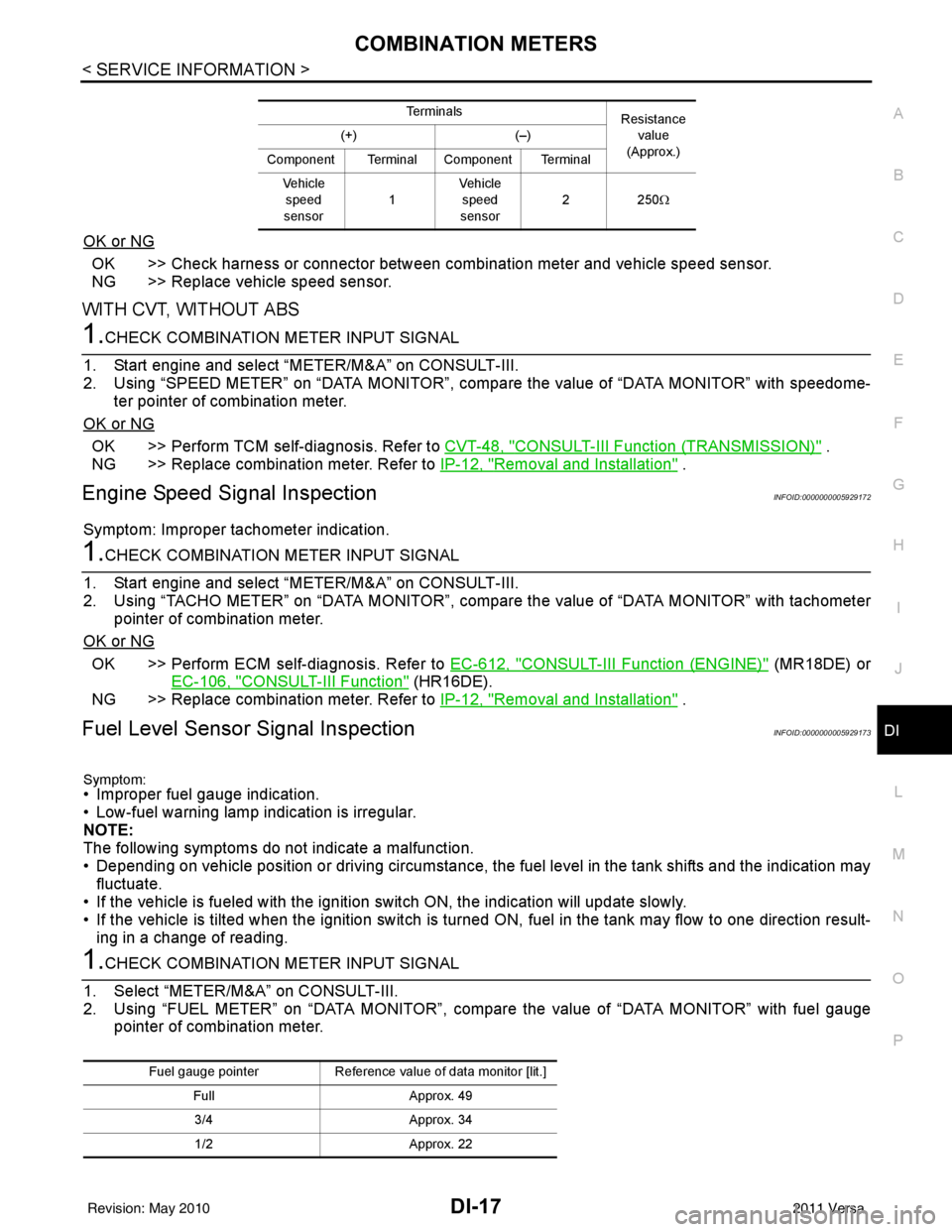
Fuel Level Sensor Signal InspectionINFOID:0000000005929173
Symptom:• Improper fuel gauge indication.
• Low-fuel warning lamp indication is irregular.
NOTE:
The following symptoms do not indicate a malfunction.
• Depending on vehicle position or driving circumstance, the fuel level in the tank shifts and the indication may fluctuate.
• If the vehicle is fueled with the ignition switch ON, the indication will update slowly.
• If the vehicle is tilted when the ignition switch is turned ON, fuel in the tank may flow to one direction result-
ing in a change of reading.
1.CHECK COMBINATION METER INPUT SIGNAL
1. Select “METER/M&A” on CONSULT-III.
2. Using “FUEL METER” on “DATA MONITOR”, compare the value of “DATA MONITOR” with fuel gauge pointer of combination meter.
Te r m i n a l s Resistance
value
(Approx.)
(+)
(–)
Component Terminal Component Terminal Ve h i c l e speed
sensor 1Vehicle
speed
sensor 22
50Ω
Fuel gauge pointer Reference value of data monitor [lit.]
Full Approx. 49
3/4 Approx. 34
1/2 Approx. 22
Revision: May 2010 2011 Versa
Page 1273 of 3787

DI-34
< SERVICE INFORMATION >
A/T INDICATOR
A/T INDICATOR
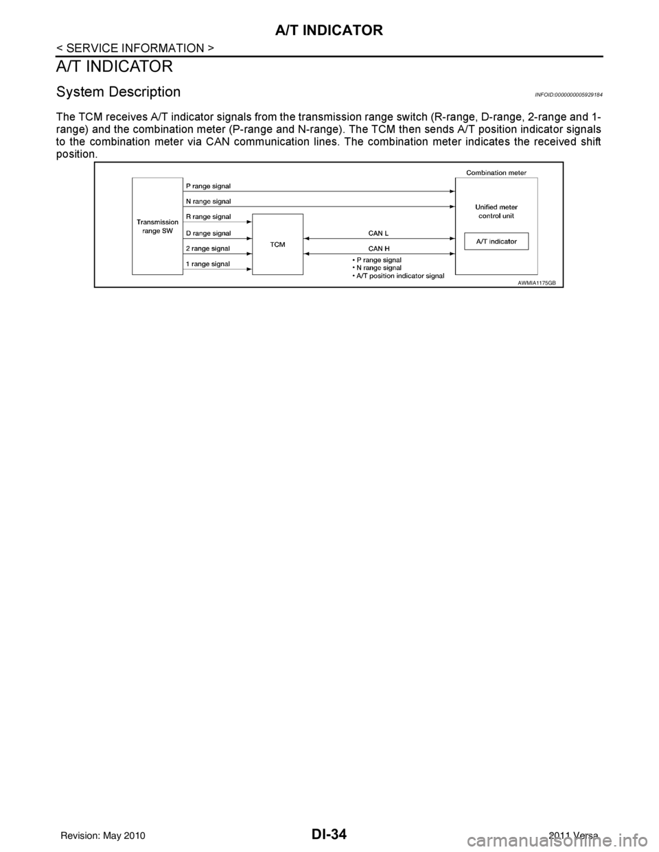
System DescriptionINFOID:0000000005929184
The TCM receives A/T indicator signals from the transmission range switch (R-range, D-range, 2-range and 1-
range) and the combination meter (P-range and N-range). The TCM then sends A/T position indicator signals
to the combination meter via CAN communication lines. The combination meter indicates the received shift
position.
AWMIA1175GB
Revision: May 20102011 Versa
Page 1276 of 3787

A/T INDICATORDI-37
< SERVICE INFORMATION >
C
DE
F
G H
I
J
L
M A
B
DI
N
O P
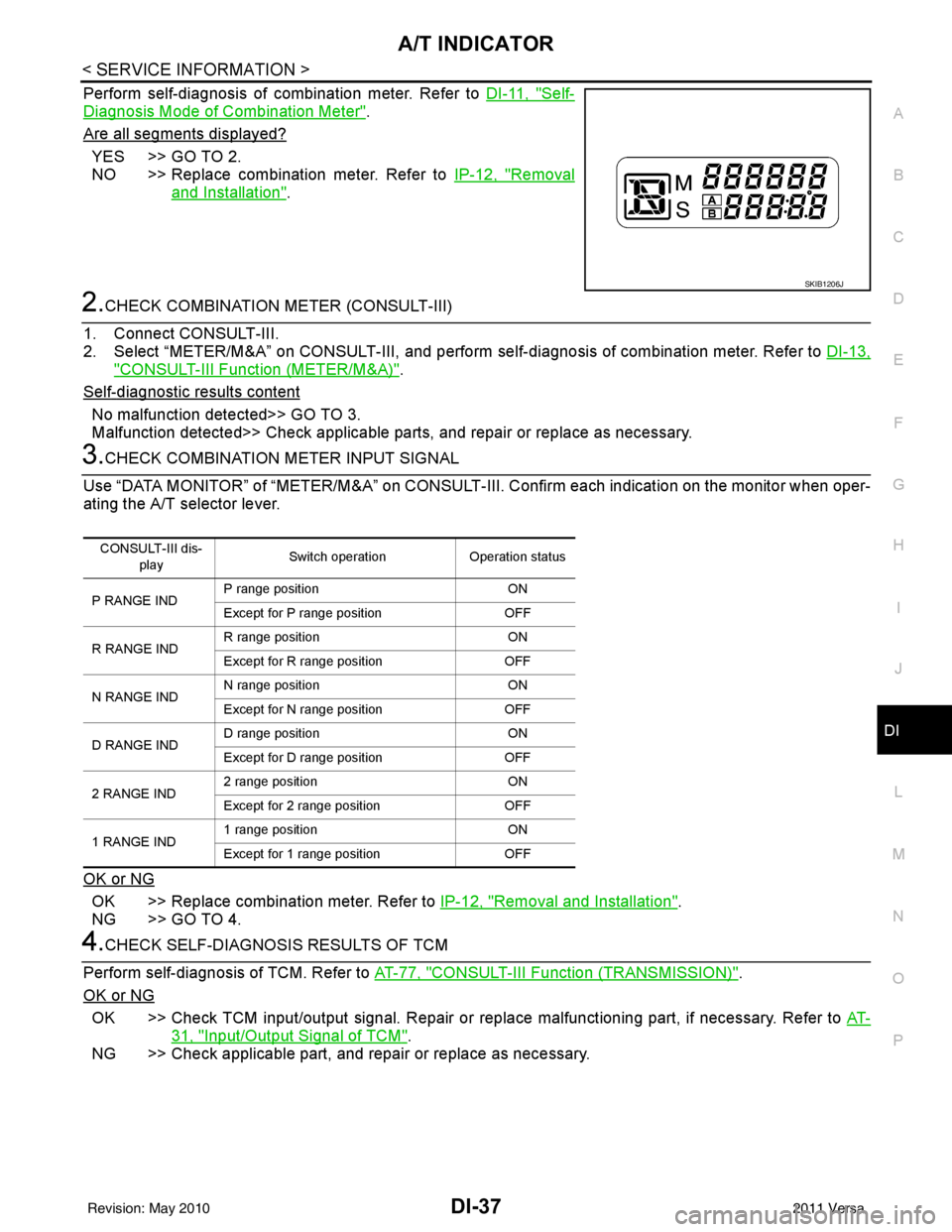
Perform self-diagnosis of combination meter. Refer to DI-11, "Self-
Diagnosis Mode of Combination Meter".
Are all segments displayed?
YES >> GO TO 2.
NO >> Replace combination meter. Refer to IP-12, "
Removal
and Installation".
2.CHECK COMBINATION METER (CONSULT-III)
1. Connect CONSULT-III.
2. Select “METER/M&A” on CONSULT-III, and perform se lf-diagnosis of combination meter. Refer to DI-13,
"CONSULT-III Function (METER/M&A)".
Self
-diagnostic results content
No malfunction detected>> GO TO 3.
Malfunction detected>> Check applicable parts, and repair or replace as necessary.
3.CHECK COMBINATION METER INPUT SIGNAL
Use “DATA MONITOR” of “METER/M&A” on CONSULT-II I. Confirm each indication on the monitor when oper-
ating the A/T selector lever.
OK or NG
OK >> Replace combination meter. Refer to IP-12, "Removal and Installation".
NG >> GO TO 4.
4.CHECK SELF-DIAGNOSIS RESULTS OF TCM
Perform self-diagnosis of TCM. Refer to AT-77, "
CONSULT-III Function (TRANSMISSION)".
OK or NG
OK >> Check TCM input/output signal. Repair or replace malfunctioning part, if necessary. Refer to AT-
31, "Input/Output Signal of TCM".
NG >> Check applicable part, and repair or replace as necessary.
SKIB1206J
CONSULT-III dis-
play Switch operation
Operation status
P RANGE IND P range position
ON
Except for P range position OFF
R RANGE IND R range position
ON
Except for R range position OFF
N RANGE IND N range position
ON
Except for N range position OFF
D RANGE IND D range position
ON
Except for D range position OFF
2 RANGE IND 2 range position
ON
Except for 2 range position OFF
1 RANGE IND 1 range position
ON
Except for 1 range position OFF
Revision: May 2010 2011 Versa