2011 NISSAN LATIO tire size
[x] Cancel search: tire sizePage 1033 of 3787
![NISSAN LATIO 2011 Service Repair Manual OVERHEATING CAUSE ANALYSISCO-33
< SERVICE INFORMATION > [MR18DE]
C
D
E
F
G H
I
J
K L
M A
CO
NP
O
Except cool-
ing system
parts mal-
function —
Overload on engine Abusive driving
High engine rpm und NISSAN LATIO 2011 Service Repair Manual OVERHEATING CAUSE ANALYSISCO-33
< SERVICE INFORMATION > [MR18DE]
C
D
E
F
G H
I
J
K L
M A
CO
NP
O
Except cool-
ing system
parts mal-
function —
Overload on engine Abusive driving
High engine rpm und](/manual-img/5/57357/w960_57357-1032.png)
OVERHEATING CAUSE ANALYSISCO-33
< SERVICE INFORMATION > [MR18DE]
C
D
E
F
G H
I
J
K L
M A
CO
NP
O
Except cool-
ing system
parts mal-
function —
Overload on engine Abusive driving
High engine rpm under no
load
Driving in low gear for ex-
tended time
Driving at extremely high
speed
Power train system mal-
function
—
Installed improper size
wheels and tires
Dragging brakes
Improper ignition timing
Blocked or restricted air
flow Blocked bumper
Installed front bumper fas-
cia cover
—
Blocked radiator grille Mud contamination or paper
clogging
Blocked radiator Blocked air flow
Blocked condenser
Installed large fog lamp
Symptom
Check items
Revision: May 2010 2011 Versa
Page 2702 of 3787
SERVICE DATA AND SPECIFICATIONS (SDS)FSU-17
< SERVICE INFORMATION >
C
DF
G H
I
J
K L
M A
B
FSU
N
O P
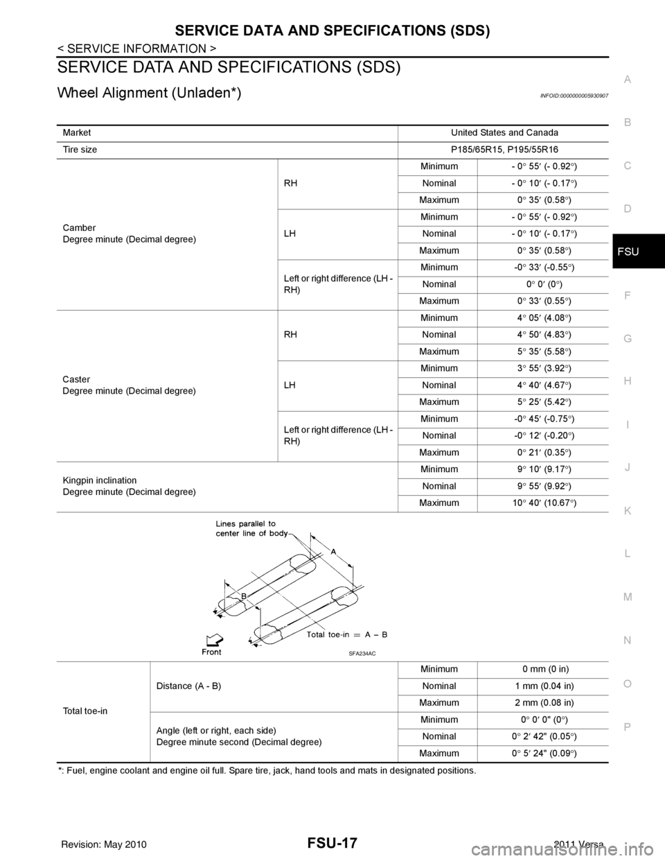
SERVICE DATA AND SPECIFICATIONS (SDS)
Wheel Alignment (Unladen*)INFOID:0000000005930907
*: Fuel, engine coolant and engine oil full. Spare tire, jack, hand tools and mats in designated positions. Market
United States and Canada
Tire size P185/65R15, P195/55R16
Camber
Degree minute (Decimal degree) RH
Minimum - 0
° 55 ′ (- 0.92 °)
Nominal - 0 ° 10 ′ (- 0.17 °)
Maximum 0 ° 35 ′ (0.58 °)
LH Minimum
- 0° 55 ′ (- 0.92 °)
Nominal - 0° 10 ′ (- 0.17 °)
Maximum 0° 35 ′ (0.58 °)
Left or right difference (LH -
RH) Minimum
-0° 33 ′ (-0.55 °)
Nominal 0° 0 ′ (0 °)
Maximum 0° 33 ′ (0.55 °)
Caster
Degree minute (Decimal degree) RH
Minimum
4° 05 ′ (4.08 °)
Nominal 4° 50 ′ (4.83 °)
Maximum 5° 35 ′ (5.58 °)
LH Minimum
3° 55 ′ (3.92 °)
Nominal 4
° 40 ′ (4.67 °)
Ma xi
mum 5° 25 ′ (5.42 °)
Left or right difference (LH -
RH) Minimum
-0° 45 ′ (-0.75 °)
Nominal -0° 12 ′ (-0.20 °)
Maximum 0° 21 ′ (0.35 °)
Kingpin inclination
Degree minute (Decimal degree) Minimum
9° 10 ′ (9.17 °)
Nominal 9° 55 ′ (9.92 °)
Maximum 10° 40 ′ (10.67 °)
Total toe-in Distance (A - B)
Minimum
0 mm (0 in)
Nominal 1 mm (0.04 in)
Maximum 2 mm (0.08 in)
Angle (left or right, each side)
Degree minute second (Decimal degree) Minimum
0° 0 ′ 0" (0 °)
Nominal 0° 2 ′ 42" (0.05 °)
Maximum 0° 5 ′ 24" (0.09 °)
SFA234AC
Revision: May 2010 2011 Versa
Page 2703 of 3787
FSU-18
< SERVICE INFORMATION >
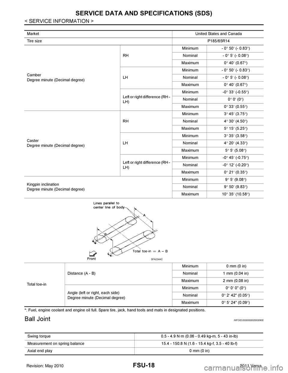
SERVICE DATA AND SPECIFICATIONS (SDS)
*: Fuel, engine coolant and engine oil full. Spare tire, jack, hand tools and mats in designated positions.
Ball JointINFOID:0000000005930908
MarketUnited States and Canada
Tire size P185/65R14
Camber
Degree minute (Decimal degree) RH
Minimum
- 0° 50 ′ (- 0.83 °)
Nominal - 0° 5 ′ (- 0.08 °)
Maximum 0° 40 ′ (0.67 °)
LH Minimum
- 0° 50 ′ (- 0.83 °)
Nominal - 0° 5 ′ (- 0.08 °)
Maximum 0° 40 ′ (0.67 °)
Left or right difference (RH -
LH) Minimum
-0° 33 ′ (-0.55 °)
Nominal 0° 0 ′ (0 °)
Maximum 0° 33 ′ (0.55 °)
Caster
Degree minute (Decimal degree) RH
Minimum
3° 45 ′ (3.75 °)
Nominal 4° 30 ′ (4.50 °)
Maximum 5° 15 ′ (5.25 °)
LH Minimum
3° 35 ′ (3 .58
°)
Nominal 4° 20 ′ (4.3
3°)
Maximum 5° 5 ′ (5.08 °)
Left or right difference (RH -
LH) Minimum
-0° 45 ′ (-0.75 °)
Nominal -0° 12 ′ (-0.20 °)
Maximum 0° 21 ′ (0.35 °)
Kingpin inclination
Degree minute (Decimal degree) Minimum
9° 5 ′ (9.08 °)
Nominal 9° 50 ′ (9.83 °)
Maximum 10° 35 ′ (10.58 °)
To t a l t o e - i n Distance (A - B)
Minimum
0 mm (0 in)
Nominal 1 mm (0.04 in)
Maximum 2 mm (0.08 in)
Angle (left or right, each side)
Degree minute (Decimal degree) Minimum
0° 0 ′ 0" (0 °)
Nominal 0° 2 ′ 42" (0.05 °)
Maximum 0° 5 ′ 24" (0.09 °)
SFA234AC
Swing torque 0.5 - 4.9 N·m (0.06 - 0.49 kg-m, 5 - 43 in-lb)
Measurement on spring balance 15.4 - 150.8 N (1.6 - 15.4 kg-f, 3.5 - 40 lb-f)
Axial end play 0 mm (0 in)
Revision: May 2010 2011 Versa
Page 2704 of 3787
SERVICE DATA AND SPECIFICATIONS (SDS)FSU-19
< SERVICE INFORMATION >
C
DF
G H
I
J
K L
M A
B
FSU
N
O P
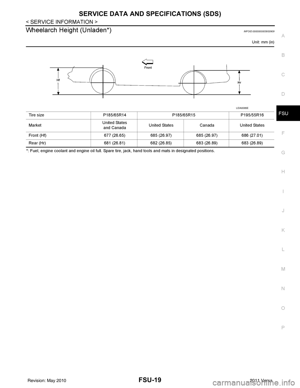
Wheelarch Height (Unladen*)INFOID:0000000005930909
Unit: mm (in)
*: Fuel, engine coolant and engine oil full. Spare tire, jack, hand tools and mats in designated positions. Tire size
P185/65R14P185/65R15P195/55R16
Market United States
and Canada United States
CanadaUnited States
Front (Hf) 677 (26.65)685 (26.97)685 (26.97)686 (27.01)
Rear (Hr) 681 (26.81)682 (26.85)683 (26.89)683 (26.89)
LEIA0085E
Revision: May 2010 2011 Versa
Page 2750 of 3787
GI-46
< SERVICE INFORMATION >
IDENTIFICATION INFORMATION
CVT NUMBER
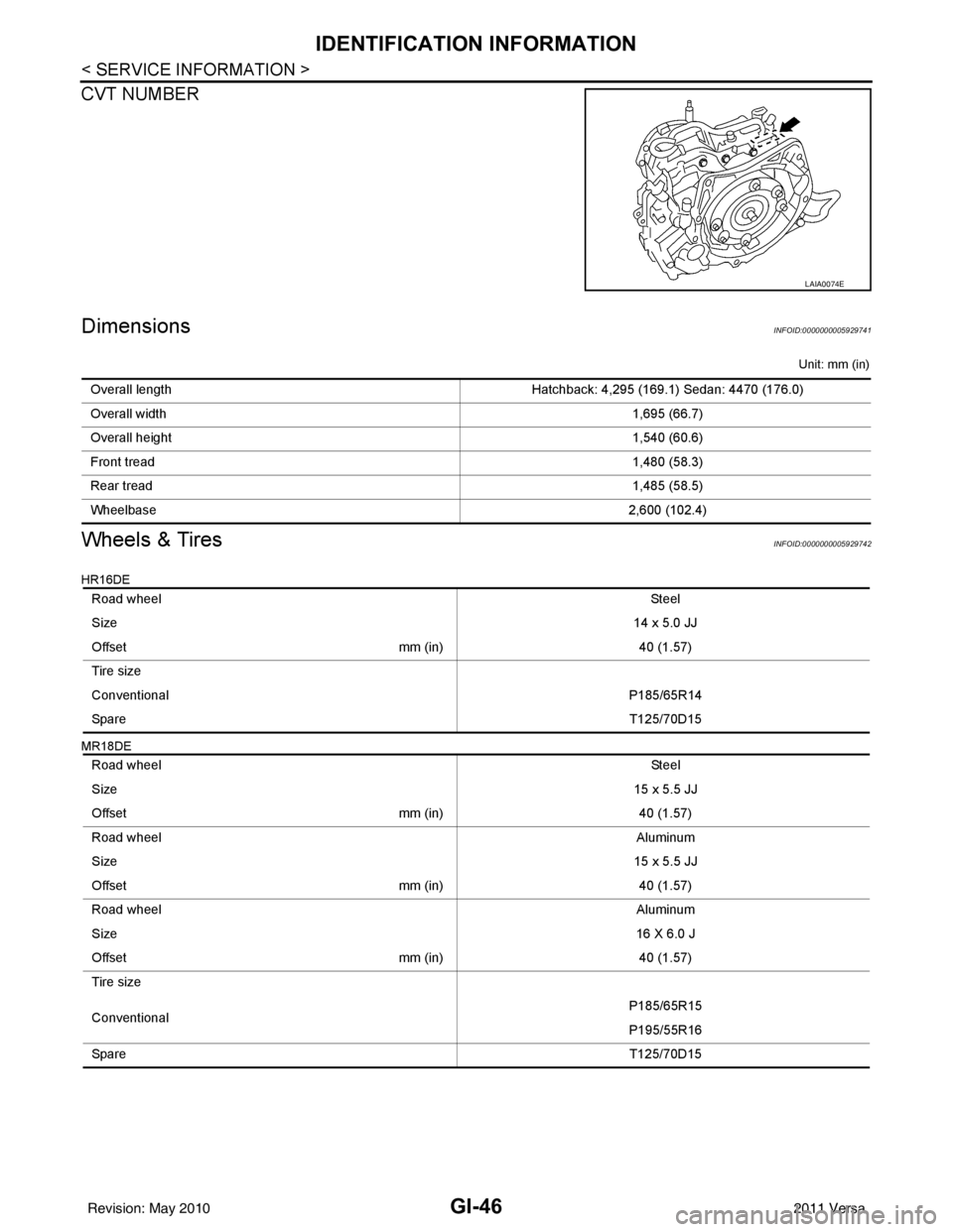
DimensionsINFOID:0000000005929741
Unit: mm (in)
Wheels & TiresINFOID:0000000005929742
HR16DE
MR18DE
LAIA0074E
Overall lengthHatchback: 4,295 (169.1) Sedan: 4470 (176.0)
Overall width 1,695 (66.7)
Overall height 1,540 (60.6)
Front tread 1,480 (58.3)
Rear tread 1,485 (58.5)
Wheelbase 2,600 (102.4)
Road wheel St ee l
Size 14 x 5.0 JJ
Offset mm (in)40 (1.57)
Tire size
Conventional P185/65R14
Spare T125/70D15
Road wheel St ee l
Size 15 x 5.5 JJ
Offset mm (in)40 (1.57)
Road wheel Aluminum
Size 15 x 5.5 JJ
Offset mm (in)40 (1.57)
Road wheel Aluminum
Size 16 X 6.0 J
Offset mm (in)40 (1.57)
Tire size
Conventional P185/65R15
P195/55R16
Spare T125/70D15
Revision: May 2010 2011 Versa
Page 3214 of 3787
CHASSIS AND BODY MAINTENANCEMA-43
< SERVICE INFORMATION >
C
DE
F
G H
I
J
K
M A
B
MA
N
O P
Do not overfill.
4. Drive vehicle for approximately 5 minutes.
5. Re-check A/T fluid level at A/T fluid temperatures of 50° to 80 °C (122° to 176°F) using “HOT” range on A/
T fluid level gauge.
CAUTION:
• When wiping the A/T fluid level gauge, always use lint-free cloth.
• Firmly fix the A/T fluid level ga uge to the A/T fluid charging pipe using the stopper attached.
6. Check A/T fluid condition and make any necessary repairs. Refer to AT-51, "
Inspections Before Trouble
Diagnosis". If the A/T fluid contains frictional material (clutches, bands, etc.), or if the A/T is repaired, over-
hauled, or replaced, inspect and clean the A/T fluid cooler mounted in the radiator. Refer to AT-18, "
A/T
Fluid Cooler Cleaning".
7. Install the removed A/T fluid level gauge into the A/T fluid charging pipe. CAUTION:
Firmly fix the A/T fluid level gaug e to the A/T fluid charging pipe using the stopper attached.
A/T FLUID : Changing A/T FluidINFOID:0000000005931176
1. Warm up A/T fluid.
2. Stop engine.
3. Drain A/T fluid by removing the drain plug. Re install the drain plug to the specified torque.
CAUTION:
Do not reuse drain plug gasket.
4. Refill the transaxle with new specified A/T fluid through the A/T fluid charging pipe. Always refill the tran- saxle with the same volume of A/T fluid that was drained out.
5. Run engine at idle speed for 5 minutes.
6. Check A/T fluid level and condition. Refer to MA-42, "
A/T FLUID : Checking A/T Fluid".
WHEELS
WHEELS : AdjustmentINFOID:0000000006413331
BALANCING WHEELS (ADHESIVE WEIGHT TYPE)
Preparation Before Adjustment
Remove inner and outer balance weights from the r oad wheel using releasing agent, remove double-faced
adhesive tape from the road wheel.
CAUTION:
• Be careful not scratch the road wheel during removal.
• After removing double-faced adhesive tape, wipe clean traces of releasing agent from the road
wheel.
Wheel Balance Adjustment
• If a balancer machine has an adhesive weight mode setting, select the adhesive weight mode setting and skip Step 2. below. If a balancer machine only has the clip-on (rim flange) weight mode setting, follow Step 2.
to calculate the correct size adhesive weight.
1. Set road wheel on balancer machine using the cent er hole as a guide. Start the balancer machine.
2. For tire balance machines that only have a clip-on (ri m flange) weight mode setting, follow this step to cal-
culate the correct size adhesive weight to use. When inner and outer imbalance values are shown on the
balancer machine indicator, multiply outer imbalance value by 5/3 (1.67) to determine balance weight that
should be used. Select the outer balance weight with a value closest to the calculated value above and
install in to the designated outer position of, or at the designated angle in relation to the road wheel.
Drain plug: Refer to
AT-237, "
Component".
Fluid grade and capacity: Refer to MA-14
.
Revision: May 2010 2011 Versa
Page 3566 of 3787
SERVICE DATA AND SPECIFICATIONS (SDS)RSU-13
< SERVICE INFORMATION >
C
DF
G H
I
J
K L
M A
B
RSU
N
O P
SERVICE DATA AND SPECIFICATIONS (SDS)
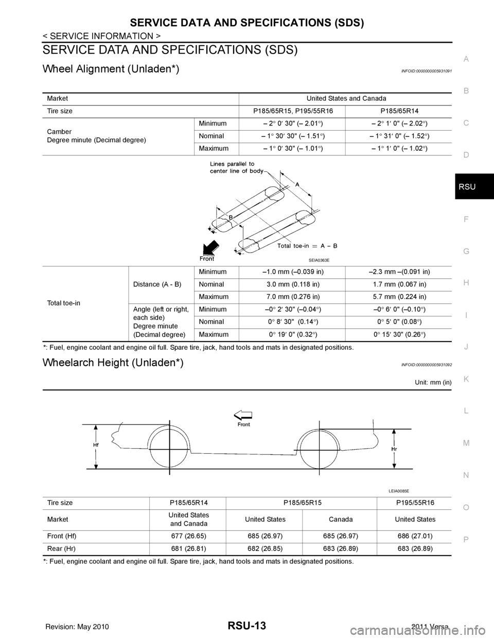
Wheel Alignment (Unladen*)INFOID:0000000005931091
*: Fuel, engine coolant and engine oil full. Spare tire, jack, hand tools and mats in designated positions.
Wheelarch Height (Unladen*)INFOID:0000000005931092
Unit: mm (in)
*: Fuel, engine coolant and engine oil full. Spare tire, jack, hand tools and mats in designated positions. Market
United States and Canada
Tire size P185/65R15, P195/55R16 P185/65R14
Camber
Degree minute (Decimal degree) Minimum – 2°
0′ 30" (– 2.01 °)– 2 ° 1 ′ 0" (– 2.02 °)
Nominal – 1 ° 30 ′ 30" (– 1.51 °)– 1° 31 ′ 0" (– 1.52 °)
Maximum – 1° 0′ 30" (– 1.01 °)– 1° 1 ′ 0" (– 1.02 °)
To t a l t o e - i n Distance (A - B)
Minimum
–1.0 mm (–0.039 in) –2.3 mm –(0.091 in)
Nominal 3.0 mm (0.118 in) 1.7 mm (0.067 in)
Maximum 7.0 mm (0.276 in) 5.7 mm (0.224 in)
Angle (left or right,
each side)
Degree minute
(Decimal degree) Minimum
–0° 2 ′ 30" (–0.04 °)– 0° 6 ′ 0" (–0.10 °)
Nominal 0° 8 ′ 30" (0.14 °)0 ° 5 ′ 0" (0.08 °)
Maximum 0° 19 ′ 0" (0.32 °)0 ° 15 ′ 30" (0.26 °)
SEIA0363E
Tire size P185/65R14P185/65R15P195/55R16
Market United States
and Canada United States
CanadaUnited States
Front (Hf) 677 (26.65)685 (26.97)685 (26.97)686 (27.01)
Rear (Hr) 681 (26.81)682 (26.85)683 (26.89)683 (26.89)
LEIA0085E
Revision: May 2010 2011 Versa
Page 3718 of 3787
![NISSAN LATIO 2011 Service Repair Manual PRECAUTIONSSTC-31
< PRECAUTION > [EPS]
C
D
E
F
H I
J
K L
M A
B
STC
N
O P
5. When the repair work is completed, return the ignition switch to the ″LOCK ″ position before connecting
the battery cab NISSAN LATIO 2011 Service Repair Manual PRECAUTIONSSTC-31
< PRECAUTION > [EPS]
C
D
E
F
H I
J
K L
M A
B
STC
N
O P
5. When the repair work is completed, return the ignition switch to the ″LOCK ″ position before connecting
the battery cab](/manual-img/5/57357/w960_57357-3717.png)
PRECAUTIONSSTC-31
< PRECAUTION > [EPS]
C
D
E
F
H I
J
K L
M A
B
STC
N
O P
5. When the repair work is completed, return the ignition switch to the ″LOCK ″ position before connecting
the battery cables. (At this time, the steering lock mechanism will engage.)
6. Perform a self-diagnosis check of al l control units using CONSULT-III.
Service Notice or Precaution for EPS SystemINFOID:0000000005931271
CAUTION:
Check or confirm the following item wh en performing the trouble diagnosis.
• Check any possible causes by interviewing the symptom and it’s condition from the customer if any
malfunction, such as EPS warn ing lamp turns ON, occurs.
• Check if air pressure and size of tires are proper, the specified part is used for the steering wheel,
and control unit is genuine part.
• Check if the connection of steer ing column assembly and steering gear assembly is proper (there is
not looseness of mounting bolts, damage of rods, boots or sealants, and leakage of grease, etc).
• Check if the wheel alignment is adjusted properly.
• Check if there is any damage or modification to su spension or body resulting in increased weight or
altered ground clearance.
• Check if installation conditions of each link and suspension are proper.
• Check if the battery voltage is proper
• Check connection conditions of each connector are proper.
• Before connecting or disconnect ing the EPS control unit har-
ness connector, turn ignition switch “OFF” and disconnect
battery ground cable. Because battery voltage is applied to
EPS control unit even if igniti on switch is turned “OFF”.
• When connecting or disconnect ing pin connectors into or
from EPS control unit, take care not to damage pin terminals
(bend or break).
When connecting pin connectors, make sure that there are no
bends or breaks on EPS control unit pin terminal.
• Before replacing EPS control unit, perform EPS control unit input/output signal inspectio n and make sure whether EPS
control unit functions properly or not. Refer to STC-20, "
Ref-
erence Value".
SEF289H
SEF291H
SDIA1848E
Revision: May 2010 2011 Versa