2011 NISSAN LATIO suspension
[x] Cancel search: suspensionPage 2647 of 3787
NOISE, VIBRATION AND HARSHNESS (NVH) TROUBLESHOOTINGFAX-5
< SERVICE INFORMATION >
CEF
G H
I
J
K L
M A
B
FA X
N
O P
NOISE, VIBRATION AND HARSHN ESS (NVH) TROUBLESHOOTING
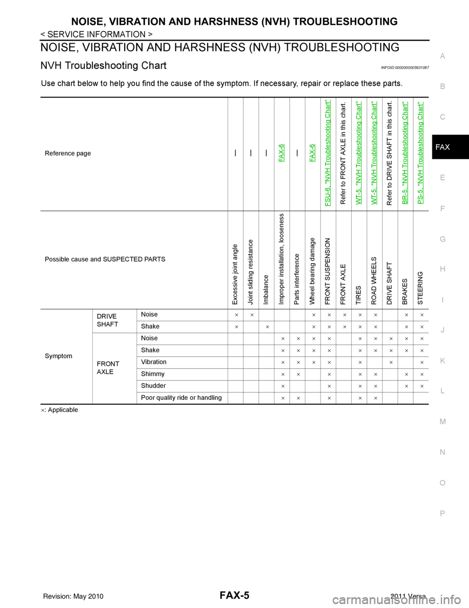
NVH Troubleshooting ChartINFOID:0000000005931067
Use chart below to help you find the cause of the symptom. If necessary, repair or replace these parts.
×: ApplicableReference page
—
—
—
FAX-6—
FAX-6
FSU-6, "
NVH Troubleshooting Chart
"
Refer to FRONT AXLE in this chart.
WT-5, "
NVH Troubleshooting Chart
"
WT-5, "
NVH Troubleshooting Chart
"
Refer to DRIVE SHAFT in this chart. BR-5, "
NVH Troubleshooting Chart
"
PS-5, "
NVH Troubleshooting Chart
"
Possible cause and SUSPECTED PARTS
Excessive joint angle
Joint sliding resistance
Imbalance
Improper installation, looseness
Parts interference
Wheel bearing damage
FRONT SUSPENSION
FRONT AXLE
TIRES
ROAD WHEELS
DRIVE SHAFT
BRAKES
STEERING
SymptomDRIVE
SHAFT
Noise
××××××× ××
Shake × × ××××× ××
FRONT
AXLE Noise
×××× ×××××
Shake ×××× ×××××
Vibration ×××××××
Shimmy ×××××××
Shudder × × ×× ××
Poor quality ride or handling ×××××
Revision: May 2010 2011 Versa
Page 2648 of 3787
FAX-6
< SERVICE INFORMATION >
FRONT WHEEL HUB AND KNUCKLE
FRONT WHEEL HUB AND KNUCKLE
On-Vehicle Inspection and ServiceINFOID:0000000005931068
• Check the axle and suspension parts for excessive play, wear, or damage.
• Shake each front wheel to check for excessive play as shown.
FRONT WHEEL BEARING INSPECTION
• Move wheel hub and bearing assembly in the axial direction by hand. Make sure the axial end play is within
specification.
• Check that the wheel hub bearing operates smoothly.
• Replace the wheel hub assembly if the axial end play exceeds specification, or if the wheel bearing does not turn smoothly. Refer to RAX-6, "
Removal and Installation".
CAUTION:
The wheel hub assembly does not requ ire maintenance. If any of the following symptoms are noted,
replace the wheel hub assembly.
• Growling noise is emitted from the wheel hub bearing during operation.
• Wheel hub bearing drags or turns roughly.
Removal and InstallationINFOID:0000000005931069
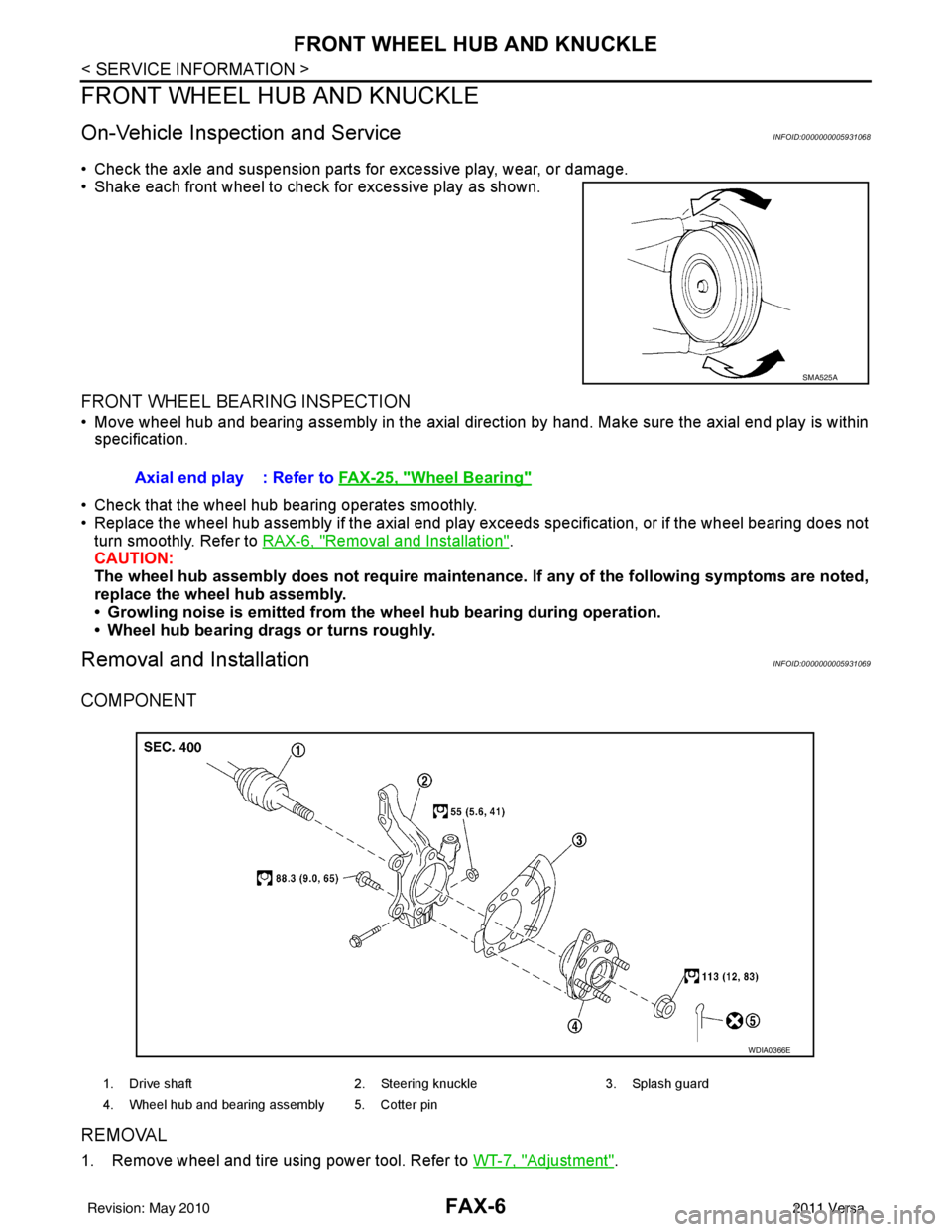
COMPONENT
REMOVAL
1. Remove wheel and tire using power tool. Refer to WT-7, "Adjustment".
SMA525A
Axial end play : Refer to FAX-25, "Wheel Bearing"
1. Drive shaft 2. Steering knuckle3. Splash guard
4. Wheel hub and bearing assembly 5. Cotter pin
WDIA0366E
Revision: May 2010 2011 Versa
Page 2680 of 3787
FUEL TANKFL-13
< SERVICE INFORMATION >
C
DE
F
G H
I
J
K L
M A
FL
NP
O
EVAP Canister
1. Check the connection for damage or any foreign materials.
2. Align the connector with the tube, then insert the c
onnector straight into the tube until a “click” sound is
heard.
3. After connecting, make sure that the connection is secure. • Pull the tube and the connector to make sure they are securely connected.
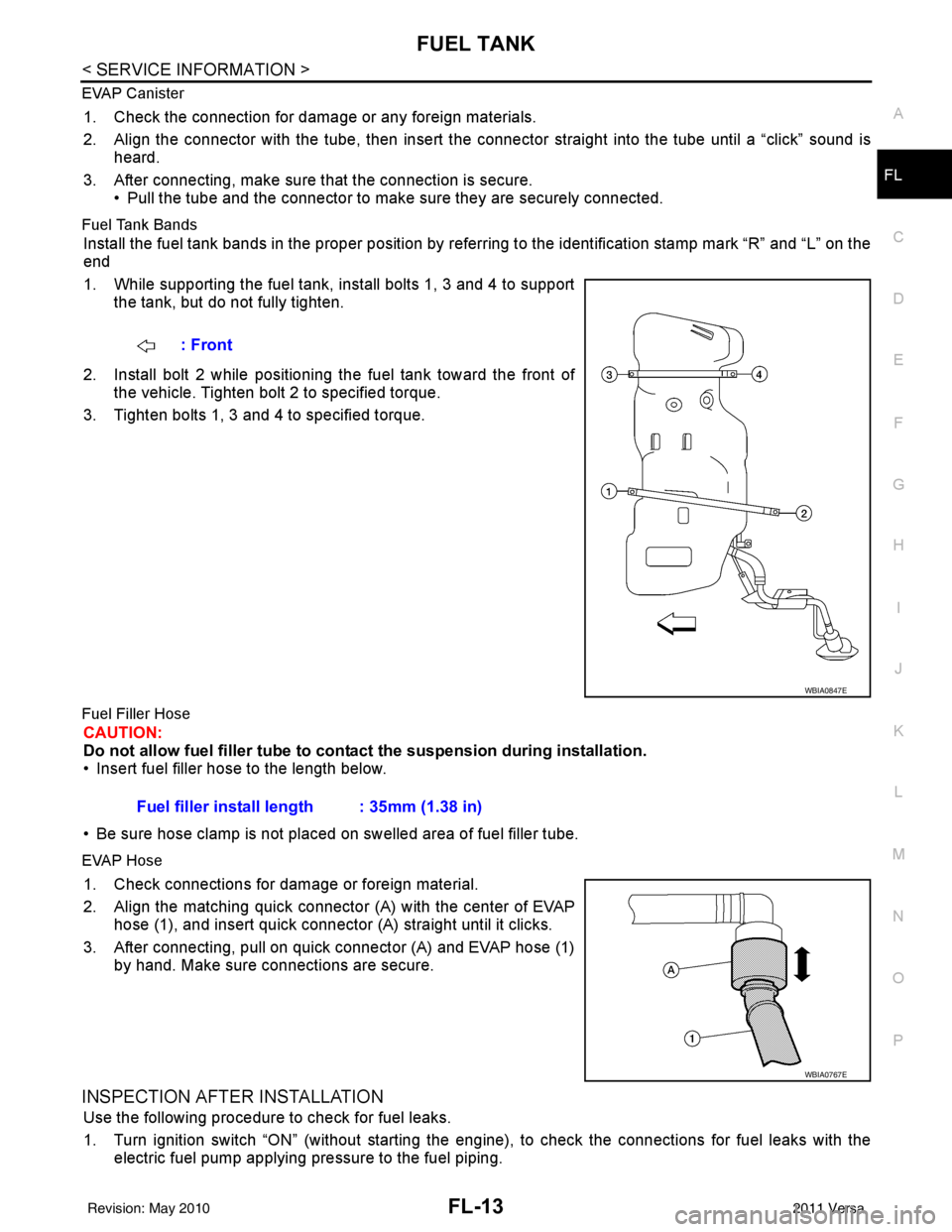
Fuel Tank Bands
Install the fuel tank bands in the proper position by referring to the identification stamp mark “R” and “L” on the
end
1. While supporting the fuel tank, install bolts 1, 3 and 4 to supportthe tank, but do not fully tighten.
2. Install bolt 2 while positioning the fuel tank toward the front of the vehicle. Tighten bolt 2 to specified torque.
3. Tighten bolts 1, 3 and 4 to specified torque.
Fuel Filler Hose
CAUTION:
Do not allow fuel filler tube to cont act the suspension during installation.
• Insert fuel filler hose to the length below.
• Be sure hose clamp is not placed on swelled area of fuel filler tube.
EVAP Hose
1. Check connections for damage or foreign material.
2. Align the matching quick connector (A) with the center of EVAP
hose (1), and insert quick connector (A) straight until it clicks.
3. After connecting, pull on quick connector (A) and EVAP hose (1) by hand. Make sure connections are secure.
INSPECTION AFTER INSTALLATION
Use the following procedure to check for fuel leaks.
1. Turn ignition switch “ON” (without starting the engi ne), to check the connections for fuel leaks with the
electric fuel pump applying pressure to the fuel piping. : Front
WBIA0847E
Fuel filler install length : 35mm (1.38 in)
WBIA0767E
Revision: May 2010
2011 Versa
Page 2686 of 3787

FSU-1
SUSPENSION
C
DF
G H
I
J
K L
M
SECTION FSU
A
B
FSU
N
O PCONTENTS
FRONT SUSPENSION
SERVICE INFORMATION .. ..........................2
PRECAUTIONS .............................................. .....2
Precaution for Supplemental Restraint System
(SRS) "AIR BAG" and "SEAT BELT PRE-TEN-
SIONER" ............................................................. ......
2
Precaution Necessary for Steering Wheel Rota-
tion After Battery Disconnect ............................... ......
2
Precaution for Procedure without Cowl Top Cover ......3
General Precautions .................................................3
PREPARATION ...................................................4
Special Service Tool ........................................... ......4
Commercial Service Tool ..........................................5
NOISE, VIBRATION AND HARSHNESS
(NVH) TROUBLESHOOTING .............................
6
NVH Troubleshooting Chart ................................ ......6
FRONT SUSPENSION ASSEMBLY ...................7
On-Vehicle Inspection and Service ..................... ......7
Wheel Alignment Inspection .....................................7
Component .......................................................... ....10
Removal and Installation .........................................11
COIL SPRING AND STRUT ..............................12
Removal and Installation .........................................12
Disposal ...................................................................12
Disassembly and Assembly .....................................13
TRANSVERSE LINK .........................................15
Removal and Installation .........................................15
STABILIZER BAR .............................................16
Removal and Installation .........................................16
SERVICE DATA AND SPECIFICATIONS
(SDS) .................................................................
17
Wheel Alignment (Unladen*) ...................................17
Ball Joint ..................................................................18
Wheelarch Height (Unladen*) ..................................19
Revision: May 2010 2011 Versa
Page 2688 of 3787
PRECAUTIONSFSU-3
< SERVICE INFORMATION >
C
DF
G H
I
J
K L
M A
B
FSU
N
O P
5. When the repair work is completed, return the ignition switch to the ″LOCK ″ position before connecting
the battery cables. (At this time, the steering lock mechanism will engage).
6. Perform a self-diagnosis check of al l control units using CONSULT-III.
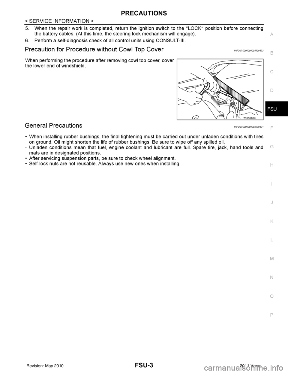
Precaution for Procedure without Cowl Top CoverINFOID:0000000005930893
When performing the procedure after removing cowl top cover, cover
the lower end of windshield.
General PrecautionsINFOID:0000000005930894
• When installing rubber bushings, the final tightening mu st be carried out under unladen conditions with tires
on ground. Oil might shorten the life of rubber bushings. Be sure to wipe off any spilled oil.
- Unladen conditions mean that fuel, engine coolant and l ubricant are full. Spare tire, jack, hand tools and
mats are in designated positions.
• After servicing suspension parts, be sure to check wheel alignment.
• Self-lock nuts are not reusable. A lways use new ones when installing.
WEIA0178E
Revision: May 2010 2011 Versa
Page 2690 of 3787
PREPARATIONFSU-5
< SERVICE INFORMATION >
C
DF
G H
I
J
K L
M A
B
FSU
N
O P
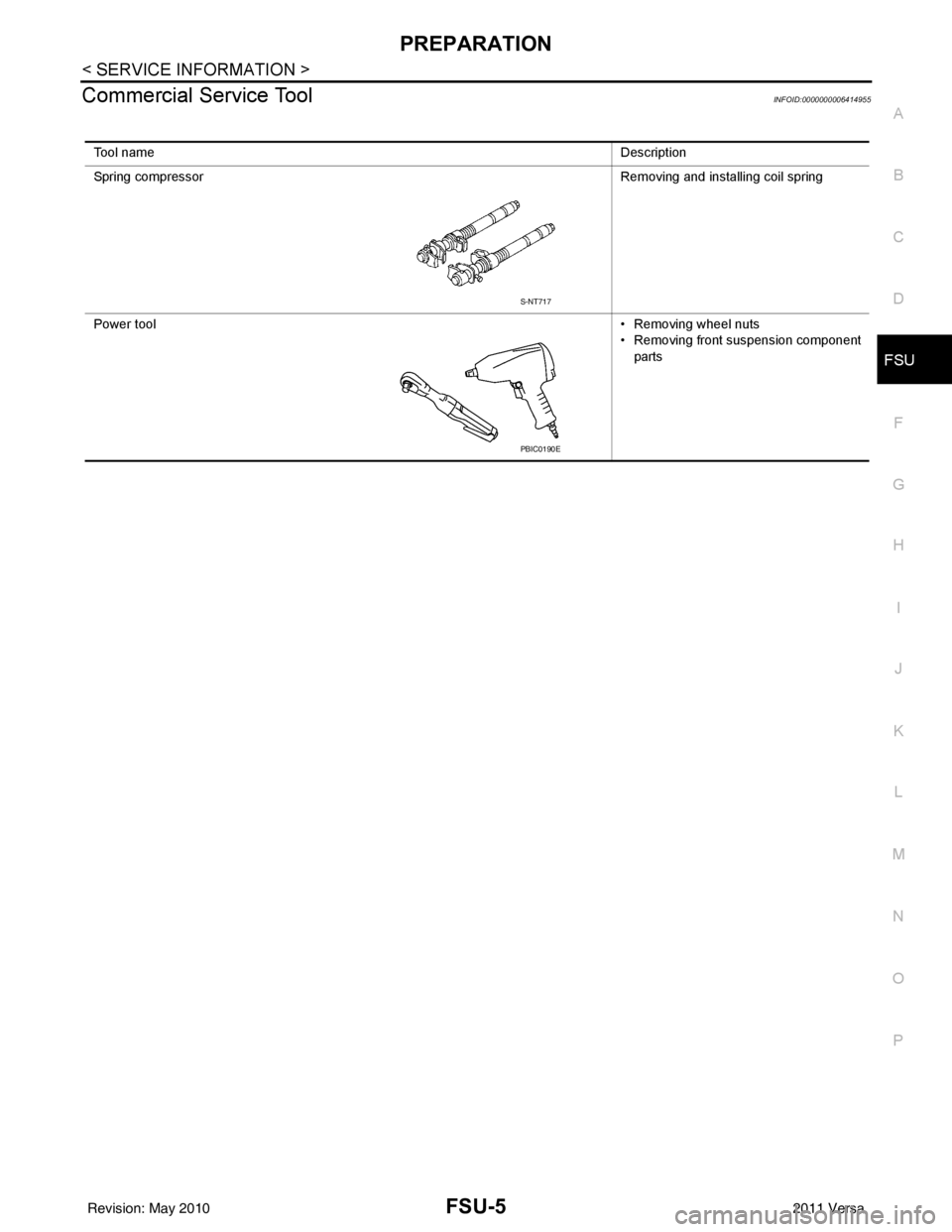
Commercial Service ToolINFOID:0000000006414955
Tool name Description
Spring compressor Removing and installing coil spring
Power tool • Removing wheel nuts
• Removing front suspension component
parts
S-NT717
PBIC0190E
Revision: May 2010 2011 Versa
Page 2691 of 3787
FSU-6
< SERVICE INFORMATION >
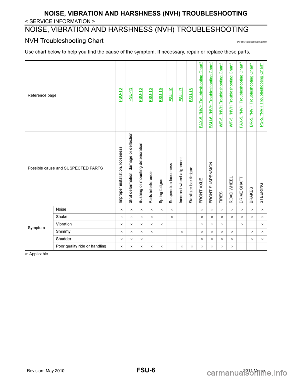
NOISE, VIBRATION AND HARSHNESS (NVH) TROUBLESHOOTING
NOISE, VIBRATION AND HARSHNESS (NVH) TROUBLESHOOTING
NVH Troubleshooting ChartINFOID:0000000005930897
Use chart below to help you find the cause of the symp tom. If necessary, repair or replace these parts.
×: ApplicableReference page
FSU-10
FSU-13FSU-10FSU-10FSU-19 FSU-10 FSU-17FSU-16
FAX-5, "
NVH Troubleshooting Chart
"
FSU-6, "
NVH Troubleshooting Chart
"
WT-5, "
NVH Troubleshooting Chart
"
WT-5, "
NVH Troubleshooting Chart
"
FAX-5, "
NVH Troubleshooting Chart
"
BR-5, "
NVH Troubleshooting Chart
"
PS-5, "
NVH Troubleshooting Chart
"
Possible cause an d SUSPECTED PARTS
Improper installation, looseness
Strut deformation, damage or deflection
Bushing or mounting deterioration
Parts interference
Spring fatigue
Suspension looseness
Incorrect wheel alignment
Stabilizer bar fatigue
FRONT AXLE
FRONT SUSPENSION
TIRES
ROAD WHEEL
DRIVE SHAFT
BRAKES
STEERING
SymptomNoise
×××××× ×××××××
Shake ×××× × ×××××××
Vibration ××××× ××× × ×
Shimmy ×××× × ×××× ××
Shudder ××× ×××× ××
Poor quality ride or handling ××××× ××××××
Revision: May 2010 2011 Versa
Page 2692 of 3787
FRONT SUSPENSION ASSEMBLYFSU-7
< SERVICE INFORMATION >
C
DF
G H
I
J
K L
M A
B
FSU
N
O P
FRONT SUSPENSION ASSEMBLY
On-Vehicle Inspection and ServiceINFOID:0000000005930898
Make sure the mounting conditions (looseness, back lash) of each component and component conditions
(wear, damage) are normal.
INSPECTION OF LOWER BALL JOINT END PLAY
1. Set front wheels in a straight-ahead position. Do not depress brake pedal.
2. Place an iron bar or similar tool between transverse link and steering knuckle.
3. Measure axial end play by prying it up and down.
CAUTION:
Be careful not to damage ball joint boot. Do not damage the installation position by applying
excessive force.
STRUT INSPECTION
Check for oil leakage, damage and replace as necessary.
Wheel Alignment InspectionINFOID:0000000005930899
PRELIMINARY INSPECTION
WARNING:
Always adjust the alignment with the vehicle on a flat surface.
NOTE:
If alignment is out of specification, inspect and replace any damaged or worn rear suspension parts before
making any adjustments.
1. Check and adjust the wheel alignment with the vehicle under unladen conditions. “Unladen conditions”
means that the fuel, coolant, and lubricant are full; and that the spare tire, jack, hand tools and mats are in
their designated positions.
2. Check the tires for incorrect air pressure and excessive wear.
3. Check the wheels for run out and damage. Refer to WT-6, "
Inspection".
4. Check the wheel bearing axial end play. Refer to FAX-6, "
On-Vehicle Inspection and Service".
5. Check the shock absorbers for leaks or damage.
6. Check each mounting point of the suspension components for any excessive looseness or damage.
7. Check each link, arm, and the suspension member for any damage.
8. Check the vehicle height. Refer to FSU-19, "
Wheelarch Height (Unladen*)".
GENERAL INFORMATION AND RECOMMENDATIONS
1. A Four-Wheel Thrust Alignment should be performed.
• This type of alignment is re commended for any NISSAN vehicle.
• The four-wheel “thrust” process helps ensure that the vehicle is properly aligned and the steering wheel
is centered.
• The alignment machine itself should be ca pable of accepting any NISSAN vehicle.
• The alignment machine should be checked to ensure that it is level.
2. Make sure the alignment machine is properly calibrated. • Your alignment machine should be regularly calibrated in order to give correct information.
• Check with the manufacturer of your specific a lignment machine for their recommended Service/Cali-
bration Schedule.
THE ALIGNMENT PROCESS
IMPORTANT: Use only the alignment specifications listed in this Service Manual. Refer to FSU-17, "Wheel
Alignment (Unladen*)".
1. When displaying the alignment settings, many alignm ent machines use “indicators”: (Green/red, plus or
minus, Go/No Go). Do NOT use these indicators.
• The alignment specifications programmed into your alignment machine that operate these indicators may not be correct.Axial end play : 0 mm (0 in)
Revision: May 2010
2011 Versa