2011 NISSAN LATIO engine
[x] Cancel search: enginePage 3073 of 3787

FRONT FOG LAMPLT-41
< SERVICE INFORMATION >
C
DE
F
G H
I
J
L
M A
B
LT
N
O P
FRONT FOG LAMP
Component Parts and Har ness Connector LocationINFOID:0000000005929065
System DescriptionINFOID:0000000005929066
The front fog lamps are controlled by lighting switch inputs to the BCM (body control module). The lighting
switch must be in the 1ST or 2ND position with the high beams OFF before the BCM will request the IPDM E/
R (intelligent power distribution module engine room) to turn the front fog lamps on. The BCM requests the
front fog lamps over the CAN communication lines to the IPDM E/R. The CPU (central processing unit) of the
IPDM E/R controls the front fog lamp relay coil ground. When energized, the relay directs power to the front
fog lamps.
OUTLINE
Power is supplied at all times:
• to front fog lamp relay (located in IPDM E/R),
• to ignition relay (located in IPDM E/R),
• through 15A fuse (No. 52, located in IPDM E/R) and
• through 20A fuse (No. 53, located in IPDM E/R)
• to CPU located in IPDM E/R,
• through 40A fusible link (letter g , located in the fuse and fusible link box)
• to BCM terminal 70,
• through 10A fuse [No. 8, located in fuse block (J/B)]
• to BCM terminal 57,
• through 10A fuse [No. 13, located in fuse block (J/B)]
• to combination meter terminal 27.
With the ignition switch in the ON or START position, power is supplied:
• to ignition relay (located in IPDM E/R),
• through 10A fuse [No. 6, located in fuse block (J/B)]
• to BCM terminal 38.
With the ignition switch in the ACC or ON position, power is supplied
• through 10A fuse [No. 20, located in fuse block (J/B)]
• to BCM terminal 11.
Ground is supplied
• to BCM terminal 67
• through grounds M57 and M61,
• to IPDM E/R terminals 39 and 59
• through grounds E15 and E24.
FOG LAMP OPERATION
The front fog lamp switch is built into the lighting switch. The lighting switch must be in 1ST position or 2ND
position and front fog lamp switch must be ON position for front fog lamp operation. The fog lamp will not oper-
ate with the high beam headlamps ON.
When the front fog lamp switch is in the ON positi on, the BCM sends a request, via the CAN communication
lines, to the CPU of the IPDM E/R to ground the coil side of the front fog lamp relay. The front fog lamp relay
then directs power
• through 15A fuse (No. 56, located in IPDM E/R)
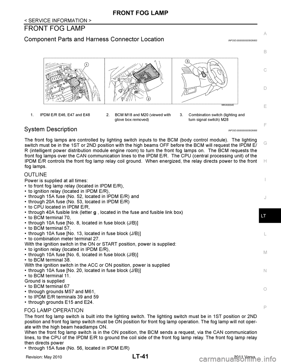
1. IPDM E/R E46, E47 and E48 2. BCM M18 and M20 (viewed with
glove box removed)3. Combination switch (lighting and
turn signal switch) M28
WKIA5554E
Revision: May 2010 2011 Versa
Page 3080 of 3787

LT-48
< SERVICE INFORMATION >
FRONT FOG LAMP
1. Check continuity between front fog lamp harness connector and
ground.
OK or NG
OK >> Replace IPDM E/R. Refer to PG-28, "Removal and
Installation of IPDM E/R" .
NG >> Repair harness or connector.
Aiming AdjustmentINFOID:0000000005929077
The front fog lamp is a semi-sealed beam type which uses a replaceable halogen bulb. Before performing
aiming adjustment, make sure of the following.
• Keep all tires inflated to correct pressure.
• Place vehicle on level surface.
• Set that there is no-load in vehicle other than the driv er (or equivalent weight placed in driver’s position).
Coolant, engine oil filled up to correct level and full fuel tank, spare tire, jack and tools are properly stowed.
Adjust aiming in the vertical direct ion by turning the adjusting screw (A).
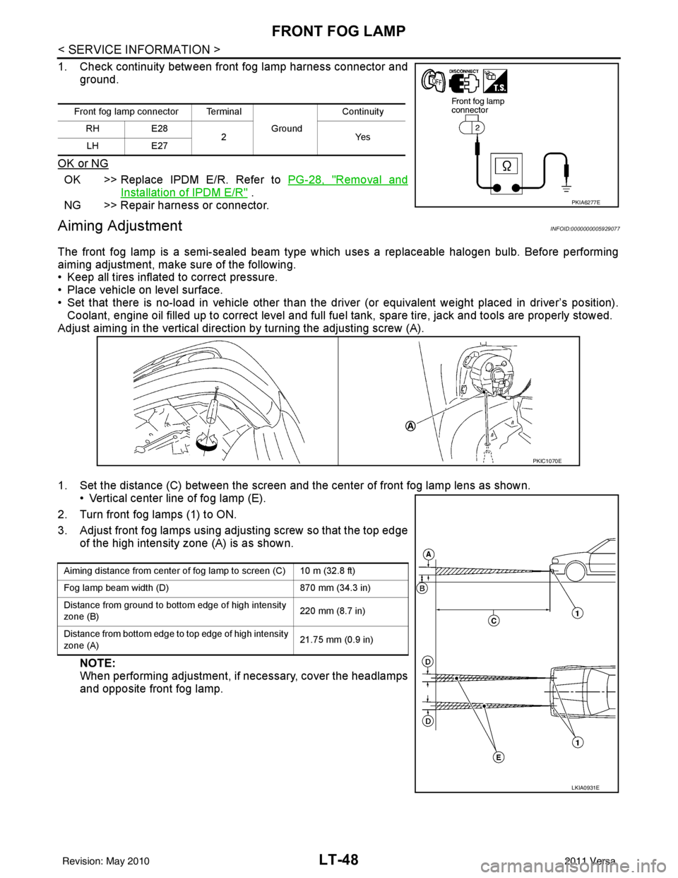
1. Set the distance (C) between the screen and the center of front fog lamp lens as shown. • Vertical center line of fog lamp (E).
2. Turn front fog lamps (1) to ON.
3. Adjust front fog lamps using adjusting screw so that the top edge of the high intensity zone (A) is as shown.
NOTE:
When performing adjustment, if necessary, cover the headlamps
and opposite front fog lamp.
Front fog lamp connector Terminal
Ground Continuity
RH E28
2Y es
LH E27
PKIA6277E
PKIC1070E
Aiming distance from center of fog lamp to screen (C) 10 m (32.8 ft)
Fog lamp beam width (D) 870 mm (34.3 in)
Distance from ground to bottom edge of high intensity
zone (B) 220 mm (8.7 in)
Distance from bottom edge to top edge of high intensity
zone (A) 21.75 mm (0.9 in)
LKIA0931E
Revision: May 2010
2011 Versa
Page 3106 of 3787

LT-74
< SERVICE INFORMATION >
PARKING, LICENSE PLATE AND TAIL LAMPS
PARKING, LICENSE PLATE AND TAIL LAMPS
Component Parts and Harness Connector LocationINFOID:0000000005929115
System DescriptionINFOID:0000000005929116
The control of the parking, license plate and tail lamp operation is dependent upon the position of lighting
switch. When the lighting switch is placed in the 1ST position, the BCM (body cont rol module) receives input
signal requesting the parking, license plate and tail lamps to illuminate. This input signal is communicated to
the IPDM E/R (intelligent power distribution module engine room) via the CAN communication lines. The CPU
(central processing unit) located in the IPDM E/R contro ls the tail lamp relay coil. This relay, when energized,
directs power to parking, license plate and tail lamps, which then illuminate.
Power is supplied at all times
• to ignition relay located in IPDM E/R,
• to tail lamp relay located in IPDM E/R,
• through 15A fuse (No. 52, located in IPDM E/R) and
• through 20A fuse (No. 53, located in IPDM E/R)
• to the CPU located in the IPDM E/R,
• through 40A fusible link (letter g , located in fuse and fusible link block)
• to BCM terminal 70,
• through 10A fuse [No. 8, located in fuse block (J/B)],
• to BCM terminal 57.
With the ignition switch in the ON or START position, power is supplied
• through 10A fuse [No. 6, located in fuse block (J/B)]
• to BCM terminal 38,
• to ignition relay located in IPDM E/R and
• through the ignition relay
• to the CPU of the IPDM E/R.
With the ignition switch in the ACC or ON position, power is supplied
• through 10A fuse [No. 20, located in fuse block (J/B)]
• to BCM terminal 11.
Ground is supplied
• to BCM terminal 67
• through grounds M20 and M61,
• to IPDM E/R terminals 59 and 39
• through grounds E15 and E24.
OPERATION BY LIGHTING SWITCH
With the lighting switch in the 1ST or 2ND position, the BCM receives an input signal requesting parking,
license plate and tail lamps to illuminate. This input signal is communicated to the IPDM E/R via the CAN com-
munication lines. The CPU, located in the IPDM E/R, controls the tail lamp relay coil. When energized, the tail
lamp relay directs power
• through 10A fuse (No. 37, located in IPDM E/R),
• through IPDM E/R terminal 26
• to front combination lamp LH terminal 6, and
• through IPDM E/R terminal 27
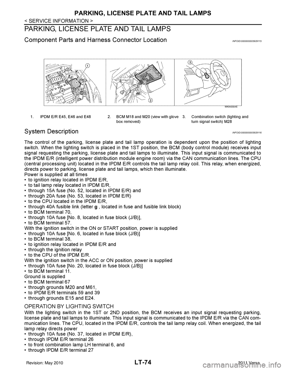
1. IPDM E/R E45, E46 and E48 2. BCM M18 and M20 (view with glove
box removed)3. Combination switch (lighting and
turn signal switch) M28
WKIA5554E
Revision: May 2010 2011 Versa
Page 3141 of 3787

ILLUMINATIONLT-109
< SERVICE INFORMATION >
C
DE
F
G H
I
J
L
M A
B
LT
N
O P
ILLUMINATION
System DescriptionINFOID:0000000005929150
The control of the illumination lamps operation is dependent upon the position of the lighting switch. When the
lighting switch is placed in the 1ST or 2ND position, the BCM (body control module) receives input signal
requesting the illumination lamps to illuminate. This input signal is communicated to IPDM E/R (intelligent
power distribution module engine room) across CAN communication lines. CPU (central processing unit)
located in the IPDM E/R controls the tail lamp relay coil . This relay, when energized, directs power to the illu-
mination lamps, which then illuminate.
Power is supplied at all times
• to ignition relay, located in IPDM E/R,
• to tail lamp relay, located in IPDM E/R,
• through 15A fuse (No. 52, located in IPDM E/R) and
• through 20A fuse (No. 53, located in IPDM E/R)
• to CPU located in IPDM E/R,
• through 40A fusible link (letter g, located in fuse and fusible link box)
• to BCM terminal 70, and
• through 10A fuse [No. 8, located in fuse block (J/B)]
• to BCM terminal 57.
With the ignition switch in the ON or START position, power is supplied
• to ignition relay, located in IPDM E/R, and
• through 10A fuse [No. 6, located in fuse block (J/B)]
• to BCM terminal 38.
With the ignition switch in the ACC or ON position, power is supplied
• through 10A fuse [No. 20, located in fuse block (J/B)]
• to BCM terminal 11.
Ground is supplied
• to BCM terminal 67
• through grounds M57 and M61
• to IPDM E/R terminals 39 and 59, and
• through grounds E15 and E24.
ILLUMINATION OPERATION BY LIGHTING SWITCH
With the lighting switch in the 1ST or 2ND positi on, BCM receives input signal requesting the illumination
lamps to illuminate. This input signal is communicat ed to IPDM E/R across CAN communication lines. CPU
located in the IPDM E/R controls the tail lamp relay coil, which, when energized, directs power
• through 10A fuse (No. 37, located in IPDM E/R)
• through IPDM E/R terminal 29
• to illumination control switch terminal 1
• to VDC OFF switch terminal 3 (with VDC)
• to audio unit terminal 9
• to front air control terminal 5
• to A/T shift selector terminal 3 (with 4-speed A/T)
• to CVT shift selector terminal 3 (with CVT)
• to hazard switch terminal 3
• to combination meter terminal 12
• to door mirror remote control switch terminal 16
• to combination switch (spiral cable) terminal 26 (with steering wheel audio control switches)
• to steering wheel audio control switches through combinat ion switch (spiral cable) terminal 18 (with steering
wheel audio control switches).
Ground is supplied
• to VDC OFF switch terminal 4 (with VDC)
• to illumination control switch terminal 3, and
• through grounds M57 and M61.
The illumination control switch controls illuminat ion intensity by varying the ground to the following
• through illumination control switch terminal 2
• to audio unit terminal 8
• to front air control terminal 6
• to A/T shift selector terminal 4 (with 4-speed A/T)
• to CVT shift selector terminal 3 (with CVT)
Revision: May 2010 2011 Versa
Page 3149 of 3787

LU-1
ENGINE
C
DE
F
G H
I
J
K L
M
SECTION LU
A
LU
N
O P
CONTENTS
ENGINE LUBRICATION SYSTEM
HR16DE
PRECAUTION ....... ........................................
2
PRECAUTIONS .............................................. .....2
Precaution for Supplemental Restraint System
(SRS) "AIR BAG" and "SEAT BELT PRE-TEN-
SIONER" ............................................................. ......
2
Precaution for Liquid Gasket .....................................2
PREPARATION ............................................4
PREPARATION .............................................. .....4
Special Service Tool ........................................... ......4
Commercial Service Tool ..........................................4
FUNCTION DIAGNOSIS ...............................6
DESCRIPTION ............................................... .....6
Engine Lubrication System ................................. ......6
Engine Lubrication System Schematic ......................6
ON-VEHICLE MAINTENANCE .....................7
ENGINE OIL ................................................... .....7
Inspection ............................................................ ......7
Draining .....................................................................8
Refilling .....................................................................8
OIL FILTER .........................................................9
Removal and Installation ...........................................9
ON-VEHICLE REPAIR .... .............................10
OIL PUMP ....................................................... ....10
Removal and Installation .........................................10
SERVICE DATA AND SPECIFICATIONS
(SDS) ......... ................................. ..................
11
SERVICE DATA AND SPECIFICATIONS
(SDS) .................................................................
11
Engine Oil Capacity ............................................. ....11
Engine Oil Pressure .................................................11
MR18DE
SERVICE INFORMATION .. .........................
12
PRECAUTIONS .................................................12
Precaution for Supplemental Restraint System
(SRS) "AIR BAG" and "SEAT BELT PRE-TEN-
SIONER" ............................................................. ....
12
Precaution Necessary for Steering Wheel Rota-
tion After Battery Disconnect ...................................
12
Precaution for Liquid Gasket ...................................13
PREPARATION .................................................14
Special Service Tool ................................................14
Commercial Service Tool ........................................14
LUBRICATION SYSTEM ..................................16
Lubrication Circuit ....................................................16
ENGINE OIL ......................................................17
Inspection ................................................................17
Changing Engine Oil ................................................18
OIL FILTER .......................................................20
Removal and Installation .........................................20
OIL PUMP .........................................................21
Component ..............................................................21
Removal and Installation .........................................21
SERVICE DATA AND SPECIFICATIONS
(SDS) .................................................................
23
Standard and Limit ..................................................23
Revision: May 2010 2011 Versa
Page 3150 of 3787
![NISSAN LATIO 2011 Service Repair Manual LU-2
< PRECAUTION >[HR16DE]
PRECAUTIONS
PRECAUTION
PRECAUTIONS
Precaution for Supplemental Restraint Syst
em (SRS) "AIR BAG" and "SEAT BELT
PRE-TENSIONER"
INFOID:0000000005928680
The Supplemental Res NISSAN LATIO 2011 Service Repair Manual LU-2
< PRECAUTION >[HR16DE]
PRECAUTIONS
PRECAUTION
PRECAUTIONS
Precaution for Supplemental Restraint Syst
em (SRS) "AIR BAG" and "SEAT BELT
PRE-TENSIONER"
INFOID:0000000005928680
The Supplemental Res](/manual-img/5/57357/w960_57357-3149.png)
LU-2
< PRECAUTION >[HR16DE]
PRECAUTIONS
PRECAUTION
PRECAUTIONS
Precaution for Supplemental Restraint Syst
em (SRS) "AIR BAG" and "SEAT BELT
PRE-TENSIONER"
INFOID:0000000005928680
The Supplemental Restraint System such as “A IR BAG” and “SEAT BELT PRE-TENSIONER”, used along
with a front seat belt, helps to reduce the risk or severity of injury to the driver and front passenger for certain
types of collision. This system includes seat belt switch inputs and dual stage front air bag modules. The SRS
system uses the seat belt switches to determine the front air bag deployment, and may only deploy one front
air bag, depending on the severity of a collision and w hether the front occupants are belted or unbelted.
Information necessary to service the system safely is included in the SRS and SB section of this Service Man-
ual.
WARNING:
• To avoid rendering the SRS inopera tive, which could increase the risk of personal injury or death in
the event of a collision which would result in air bag inflation, all maintenance must be performed by
an authorized NISSAN/INFINITI dealer.
• Improper maintenance, including incorrect removal and installation of the SRS can lead to personal
injury caused by unintent ional activation of the system. For re moval of Spiral Cable and Air Bag
Module, see the SRS section.
• Do not use electrical test equipmen t on any circuit related to the SRS unless instructed to in this
Service Manual. SRS wiring harn esses can be identified by yellow and/or orange harnesses or har-
ness connectors.
PRECAUTIONS WHEN USING POWER TOOLS (AIR OR ELECTRIC) AND HAMMERS
WARNING:
• When working near the Airbag Diagnosis Sensor Unit or other Airbag System sensors with the Igni-
tion ON or engine running, DO NOT use air or electri c power tools or strike near the sensor(s) with a
hammer. Heavy vibration could activate the sensor( s) and deploy the air bag(s), possibly causing
serious injury.
• When using air or electric power tools or hammers , always switch the Ignition OFF, disconnect the
battery, and wait at least 3 minu tes before performing any service.
Precaution for Liquid GasketINFOID:0000000005928682
REMOVAL OF LIQUID GASKET SEALING
• After removing nuts and bolts, separate the mating surface, using Tool and remove old liquid gasket sealing.
CAUTION:
Be careful not to damage the mating surfaces.
• Tap Tool to insert it (1), and then slide it by tapping on the side (2)
as shown.
• In areas where Tool is difficult to use, use plastic hammer to lightly tap the parts, to remove it.
CAUTION:
If for some unavoidable reason suitable tool such as screw-
driver is used, be careful no t to damage the mating surfaces.
LIQUID GASKET APPLICATION PROCEDURE
Tool number : KV10111100 (J-37228)
WBIA0566E
Revision: May 2010 2011 Versa
Page 3151 of 3787
![NISSAN LATIO 2011 Service Repair Manual PRECAUTIONSLU-3
< PRECAUTION > [HR16DE]
C
D
E
F
G H
I
J
K L
M A
LU
NP
O
1. Remove old liquid gasket adhering to the liquid gasket applica-
tion surface and the mating surface, using scraper.
• Remov NISSAN LATIO 2011 Service Repair Manual PRECAUTIONSLU-3
< PRECAUTION > [HR16DE]
C
D
E
F
G H
I
J
K L
M A
LU
NP
O
1. Remove old liquid gasket adhering to the liquid gasket applica-
tion surface and the mating surface, using scraper.
• Remov](/manual-img/5/57357/w960_57357-3150.png)
PRECAUTIONSLU-3
< PRECAUTION > [HR16DE]
C
D
E
F
G H
I
J
K L
M A
LU
NP
O
1. Remove old liquid gasket adhering to the liquid gasket applica-
tion surface and the mating surface, using scraper.
• Remove liquid gasket completely from the groove of the liquidgasket application surface, bolts, and bolt holes.
2. Thoroughly clean the mating surfaces and remove adhering moisture, grease and foreign materials.
3. Attach liquid gasket tube to Tool.
Use Genuine RTV Silicone Seal ant or equivalent. Refer to GI-42, "
Recommended Chemical Prod-
uct and Sealant".
4. Apply liquid gasket without breaks to the specified location with the specified dimensions. • If there is a groove for the liquid gasket application, apply liquid gasket to the groove.
• As for the bolt holes, normally apply liquid gasket inside theholes. Occasionally, it should be applied outside the holes.
Make sure to read the text of service manual.
• Within five minutes of liquid gasket application, install the mat-
ing component.
• If liquid gasket protrudes, wipe it off immediately.
• Do not retighten nuts or bolts after the installation.
• After 30 minutes or more have passed from the installation, fill engine oil and engine coolant.
CAUTION:
If there are specific instructions in this manual, observe them.
Tool number : WS39930000 ( — )
PBIC0003E
WBIA0567E
SEM159F
Revision: May 2010
2011 Versa
Page 3154 of 3787
![NISSAN LATIO 2011 Service Repair Manual LU-6
< FUNCTION DIAGNOSIS >[HR16DE]
DESCRIPTION
FUNCTION DIAGNOSIS
DESCRIPTION
Engine Lubrication SystemINFOID:0000000005928685
Engine Lubricati
on System SchematicINFOID:0000000005928686
JPBIA0325GB
NISSAN LATIO 2011 Service Repair Manual LU-6
< FUNCTION DIAGNOSIS >[HR16DE]
DESCRIPTION
FUNCTION DIAGNOSIS
DESCRIPTION
Engine Lubrication SystemINFOID:0000000005928685
Engine Lubricati
on System SchematicINFOID:0000000005928686
JPBIA0325GB](/manual-img/5/57357/w960_57357-3153.png)
LU-6
< FUNCTION DIAGNOSIS >[HR16DE]
DESCRIPTION
FUNCTION DIAGNOSIS
DESCRIPTION
Engine Lubrication SystemINFOID:0000000005928685
Engine Lubricati
on System SchematicINFOID:0000000005928686
JPBIA0325GB
JPBIA0326GB
Revision: May 2010 2011 Versa