Page 2351 of 3787

REAR BUMPEREI-21
< ON-VEHICLE REPAIR >
C
DE
F
G H
J
K L
M A
B
EI
N
O P
Removal and Installation - SedanINFOID:0000000005929557
REMOVAL
1. Open trunk lid.
2. Remove rear combination lamp RH/LH. Refer to LT-88, "
Removal and Installation".
3. Remove rear bumper fascia spring nuts and screws RH/LH.
4. Remove rear fender protector. Refer to EI-26, "
Removal and Installation".
5. Pull the rear bumper fascia side outward and release the bumper side bracket.
6. Remove rear bumper fascia upper clips and screws.
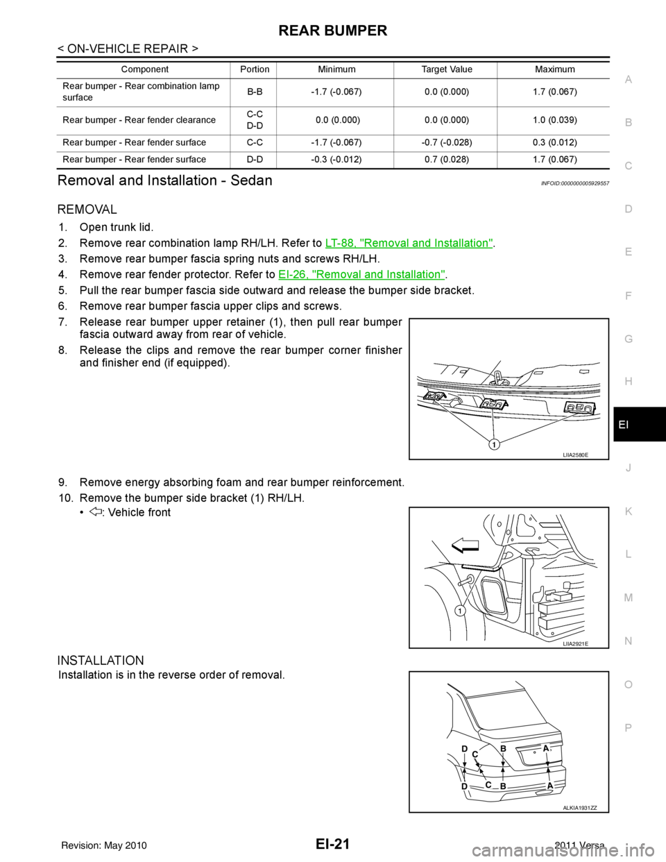
7. Release rear bumper upper retainer (1), then pull rear bumper fascia outward away from rear of vehicle.
8. Release the clips and remove the rear bumper corner finisher and finisher end (if equipped).
9. Remove energy absorbing foam and rear bumper reinforcement.
10. Remove the bumper side bracket (1) RH/LH. • : Vehicle front
INSTALLATION
Installation is in the reverse order of removal.
Rear bumper - Rear combination lamp
surface B-B
-1.7 (-0.067) 0.0 (0.000)1.7 (0.067)
Rear bumper - Rear fender clearance C-C
D-D
0.0 (0.000)
0.0 (0.000)1.0 (0.039)
Rear bumper - Rear fender surface C-C -1.7 (-0.067)-0.7 (-0.028) 0.3 (0.012)
Rear bumper - Rear fender surface D-D -0.3 (-0.012)0.7 (0.028)1.7 (0.067)
Component
PortionMinimum Target Value Maximum
LIIA2580E
LIIA2921E
ALKIA1931ZZ
Revision: May 2010 2011 Versa
Page 2352 of 3787
EI-22
< ON-VEHICLE REPAIR >
REAR BUMPER
mm (in)
ComponentPortionMinimum Target Value Maximum
Rear bumper - Trunk lid clearance A-A 4.8 (0.189)7.0 (0.276)9.2 (0.362)
Rear bumper - Rear combination lamp
clearance B-B
1.0 (0.039) 2.0 (0.079)3.5 (0.138)
Rear bumper - Rear combination lamp
surface B-B
-1.2 (-0.047) 0.0 (0.000)1.2 (0.047)
Rear bumper - Rear fender clearance C-C
D-D 0.0 (0.000)
0.0 (0.000)1.0 (0.039)
Rear bumper - Rear fender surface C-C
D-D-1.7 (-0.067)
-0.7 (0.028)0.3 (0.012)
Revision: May 2010 2011 Versa
Page 2363 of 3787
TRUNK LID FINISHEREI-33
< ON-VEHICLE REPAIR >
C
DE
F
G H
J
K L
M A
B
EI
N
O P
TRUNK LID FINISHER
Removal and InstallationINFOID:0000000005929567
REMOVAL
1. Open trunk lid, remove trunk lid finisher inner. Refer to EI-59.
2. Remove trunk lid finisher outer nuts.
3. Release the clips, then pull trunk lid finisher outer away from trunk lid.
4. Disconnect trunk lid opener switch connector and trunk opener request switch connector, then remove trunk lid finisher outer.
INSTALLATION
Installation is in the reverse order of removal.
1. Trunk lid finisher outer 2. Trunk lid opener switch connector 3. Trunk opener request switch connector
A. Clip C101
WIIA1413E
Revision: May 2010 2011 Versa
Page 2365 of 3787

REAR AIR SPOILEREI-35
< ON-VEHICLE REPAIR >
C
DE
F
G H
J
K L
M A
B
EI
N
O P
2. Remove inside trunk lid finisher. Refer to EI-59, "Removal and Installation".
3. Disconnect high mounted stop lamp connector.
4. Release adhesive backed foam tape and clips, then carefully lift the rear air spoiler from trunk lid. CAUTION:
Use care not to damage painted surfaces during removal, or releasing of adhesive backed foam
tapes if equipped.
5. Release the high mounted stop lamp harness grommet from trunk lid, then remove rear air spoiler.
Installation - Sedan
Installation is in the reverse order of removal.
NOTE:
• Before installing rear air spoiler, clean the surface where it will be mounted with isopropyl alcohol or equiva-
lent to degrease the surface.
• Before installing, be sure there are no gaps or wa ves in the foam tape (if equipped) where the surfaces
meet.
• During installation, be sure grommet of high mounted stop lamp harness is fully seated into trunk lid opening prior to final rear air spoiler placement.
Removal - Hatchback
1. Remove back door finisher upper. Refer to EI-40.
2. Disconnect high mounted stop lamp connector.
3. Remove the nuts and carefully lift the rear air spoiler from the back door. CAUTION:
Use care not to damage painted surfaces during removal, or releasing of adhesive backed foam
tapes if equipped.
4. Release the high mounted stop lamp harness grommet from back door, then remove rear air spoiler.
Installation - Hatchback
Installation is in the reverse order of removal.
NOTE:
• Before installing rear air spoiler, clean the surface where it will be mounted with isopropyl alcohol or equiva-
lent to degrease the surface.
• Before installing, be sure there are no gaps or wa ves in the foam tape (if equipped) where the surfaces
meet.
• During installation, be sure grommet of high mount ed stop lamp harness is fully seated into back door open-
ing prior to final rear air spoiler placement.
Revision: May 2010 2011 Versa
Page 2389 of 3787
TRUNK ROOM TRIM & TRUNK LID FINISHEREI-59
< ON-VEHICLE REPAIR >
C
DE
F
G H
J
K L
M A
B
EI
N
O P
TRUNK ROOM TRIM & TRUNK LID FINISHER
Removal and InstallationINFOID:0000000005929579
REMOVAL
CAUTION:
• Insert a trim stick or suitable tool between panel on vehicle and clips (as indicated with arrow) to release clips.
• Be careful not to damage the body while prying to release clips.
• Make sure clips are properly al igned in panel holes on body
when installing, then press them in completely.
1. Open trunk lid.
2. Position the rear seat cushion to the forward most position, then remove the rear seatback and seatback side RH/LH. Refer to
SE-22, "
Removal and Installation".
1. Trunk side finisher RH 2. Seat back finisher RH (if equipped) 3. Trunk floor carpet
4. Seat back finisher LH (if equipped) 5. Trunk side finisher LH 6. Trunk rear plate
7. Trunk lid finisher inner A. Clip C205 Vehicle front
Pawl
WIIA1415E
SIIA0810E
Revision: May 2010 2011 Versa
Page 2390 of 3787
EI-60
< ON-VEHICLE REPAIR >
TRUNK ROOM TRIM & TRUNK LID FINISHER
3. Release the clips, then remove the seatback finisher RH/LH.
4. Lift and remove the trunk floor carpet.
5. Release the clips, then remove the trunk rear plate.
6. Release the clips, then remove the trunk side finisher RH/LH.
7. Release the clips and remove the trunk lid finisher inner from the trunk lid.
INSTALLATION
Installation is in the reverse order of removal.
Revision: May 20102011 Versa
Page 2722 of 3787
GI-18
< SERVICE INFORMATION >
HOW TO USE THIS MANUAL
• Letter designations next to test meter probe indicate harness (con-nector) wire color.
• Connector numbers in a single circle M33 indicate harness con-
nectors.
Component Indication
Connector numbers in a double circle F211 indicate component connectors.
Switch Positions
Switches are shown in wiring diagrams as if the vehicle is in the “normal” condition.
A vehicle is in the “normal” condition when:
• ignition switch is “OFF”,
• doors, hood and trunk lid/back door are closed,
• pedals are not depressed, and
• parking brake is released.
Detectable Lines and Non-Detectable Lines
In some wiring diagrams, two kinds of lines, r epresenting wires, with different weight are used.
AGI070
SGI860
Revision: May 2010 2011 Versa
Page 2762 of 3787

GW-8
< SERVICE INFORMATION >
SQUEAK AND RATTLE TROUBLE DIAGNOSES
SILICONE GREASE
Used instead of UHMW tape that will be visible or not fit.
Note: Will only last a few months.
SILICONE SPRAY
Use when grease cannot be applied.
DUCT TAPE
Use to eliminate movement.
CONFIRM THE REPAIR
Confirm that the cause of a noise is repaired by test driving the vehicle. Operate the vehicle under the same
conditions as when the noise originally occurred. Refer to the notes on the Diagnostic Worksheet.
Generic Squeak and Rattle TroubleshootingINFOID:0000000005929463
Refer to Table of Contents for specific component removal and installation information.
INSTRUMENT PANEL
Most incidents are caused by contact and movement between:
1. The cluster lid A and instrument panel
2. Acrylic lens and combination meter housing
3. Instrument panel to front pillar garnish
4. Instrument panel to windshield
5. Instrument panel mounting pins
6. Wiring harnesses behind the combination meter
7. A/C defroster duct and duct joint
These incidents can usually be located by tapping or moving the components to duplicate the noise or by
pressing on the components while driving to stop the noise. Most of these incidents can be repaired by apply-
ing felt cloth tape or silicone spray (in hard to reach areas). Urethane pads can be used to insulate wiring har-
ness.
CAUTION:
Do not use silicone spray to isolate a squeak or rattle. If you saturate the ar ea with silicone, you will
not be able to recheck the repair.
CENTER CONSOLE
Components to pay attention to include:
1. Shift selector cover to finisher
2. A/C control unit and cluster lid C
3. Wiring harnesses behind audio and A/C control unit
The instrument panel repair and isolation pr ocedures also apply to the center console.
DOORS
Pay attention to the:
1. Finisher and inner panel making a slapping noise
2. Inside handle escutcheon to door finisher
3. Wiring harnesses tapping
4. Door striker out of alignment causing a popping noise on starts and stops
Tapping or moving the components or pressing on them wh ile driving to duplicate the conditions can isolate
many of these incidents. You can usually insulate the areas with felt cloth tape or insulator foam blocks from
the NISSAN Squeak and Rattle Kit (J-43980) to repair the noise.
TRUNK
Trunk noises are often caused by a loose jack or loose items put into the trunk by the owner.
In addition look for:
1. Trunk lid bumpers out of adjustment
2. Trunk lid striker out of adjustment
3. The trunk lid torsion bars knocking together
4. A loose license plate or bracket
Revision: May 2010 2011 Versa