Page 6 of 377
Table of
ContentsIllustrated table of contents
Safety—Seats, seat belts and supplemental restraint system
Instruments and controls
Pre-driving checks and adjustments
Heater, air conditioner, audio and phone systems
Starting and driving
In case of emergency
Appearance and care
Maintenance and do-it-yourself
Technical and consumer information
Index
0
1
2
3
4
5
6
7
8
9
10
Page 13 of 377
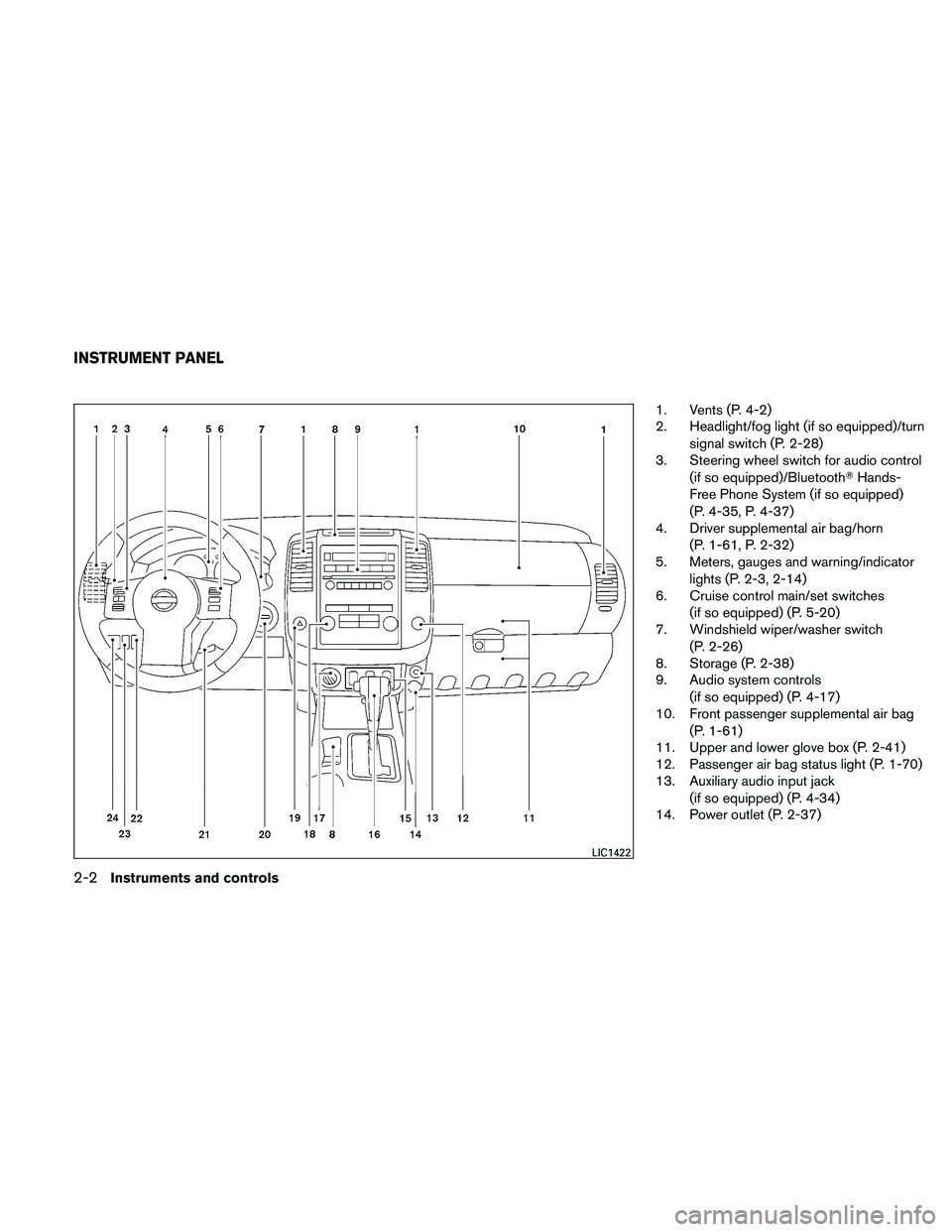
1. Vents (P. 4-2)
2. Headlight/fog light (if so equipped)/turnsignal switch (P. 2-28)
3. Steering wheel switch for audio control
(if so equipped)/Bluetooth� Hands-
Free Phone System (if so equipped)
(P. 4-35, P. 4-37)
4. Driver supplemental air bag/horn
(P. 1-61, P. 2-32)
5. Meters, gauges and warning/indicator
lights (P. 2-3, 2-14)
6. Cruise control main/set switches
(if so equipped) (P. 5-20)
7. Windshield wiper/washer switch
(P. 2-26)
8. Storage (P. 2-38)
9. Audio system controls
(if so equipped) (P. 4-17)
10. Front passenger supplemental air bag
(P. 1-61)
11. Upper and lower glove box (P. 2-41)
12. Passenger air bag status light (P. 1-70)
13. Auxiliary audio input jack
(if so equipped) (P. 4-34)
14. Power outlet (P. 2-37)
LIC1422
INSTRUMENT PANEL
0-6Illustrated table of contents
Page 99 of 377
1. Vents (P. 4-2)
2. Headlight/fog light (if so equipped)/turnsignal switch (P. 2-28)
3. Steering wheel switch for audio control
(if so equipped)/Bluetooth� Hands-
Free Phone System (if so equipped)
(P. 4-35, P. 4-37)
4. Driver supplemental air bag/horn
(P. 1-61, P. 2-32)
5. Meters, gauges and warning/indicator
lights (P. 2-3, 2-14)
6. Cruise control main/set switches
(if so equipped) (P. 5-20)
7. Windshield wiper/washer switch
(P. 2-26)
8. Storage (P. 2-38)
9. Audio system controls
(if so equipped) (P. 4-17)
10. Front passenger supplemental air bag
(P. 1-61)
11. Upper and lower glove box (P. 2-41)
12. Passenger air bag status light (P. 1-70)
13. Auxiliary audio input jack
(if so equipped) (P. 4-34)
14. Power outlet (P. 2-37)
LIC1422
INSTRUMENT PANEL
2-2Instruments and controls
Page 160 of 377

As many as 5 keyfobs can be used with one
vehicle. For information concerning the purchase
and use of additional keyfobs, contact a NISSAN
dealer.
The keyfob will not function when:● the battery is discharged
● the distance between the vehicle and the
keyfob is over 33 ft (10 m)
The panic alarm will not activate when the
key is in the ignition switch.
CAUTION
Listed below are conditions or occur-
rences which will damage the keyfob:
● Do not allow the keyfob, which contains
electrical components, to come into
contact with water or salt water. This
could affect the system function.
● Do not drop the keyfob.
● Do not strike the keyfob sharply against
another object.
● Do not change or modify the keyfob.
● Wetting may damage the keyfob. If the
keyfob gets wet, immediately wipe until
it is completely dry. ●
Do not place the keyfob for an extended
period in an area where temperatures
exceed 140°F (60°C) .
● Do not attach the keyfob with a key
holder that contains a magnet.
● Do not place the keyfob near equip-
ment that produces a magnetic field,
such as a TV, audio equipment and per-
sonal computers.
If a keyfob is lost or stolen, NISSAN rec-
ommends erasing the ID code of that key-
fob. This will prevent the keyfob from un-
authorized use to unlock the vehicle. For
information regarding the erasing proce-
dure, please contact a NISSAN dealer.HOW TO USE REMOTE KEYLESS
ENTRY SYSTEM
Locking doors
1. Close all windows.
2. Remove the key from the ignition switch.
3. Close the hood and all doors.
4. Press the
button on the keyfob. All
the doors lock. The hazard warning lights
flash twice and the horn beeps once to
indicate all doors are locked.
LPD0209
Pre-driving checks and adjustments3-7
Page 174 of 377
 (Type A) ..........4-2
Controls ............................")
4 Heater, air conditioner, audio and phone
systems
Vents............................................4-2
Heater and air conditioner (manual) (Type A) ..........4-2
Controls .......................................4-3
Heater operation ...............................4-4
Air conditioner operation (if so equipped) .........4-5
Air flow charts ..................................4-7
Heater and air conditioner (manual) (Type B) .........4-10
Controls ...................................... 4-10
Heater operation .............................. 4-11
Air conditioner operation .......................4-12
Air flow charts ................................. 4-14
Servicing air conditioner (if so equipped) ............4-17
Audio system .................................... 4-17
Radio (if so equipped) ......................... 4-17
FM radio reception ............................ 4-17
AM radio reception ............................ 4-18
Satellite radio reception (if so equipped) .........4-18
Audio operation precautions ....................4-18FM/AM radio with compact disc (CD) player
(Type A and B) (if so equipped)
.................4-25
FM/AM/SAT radio with compact disc (CD)
changer (if so equipped) .......................4-29
CD care and cleaning .......................... 4-35
Steering wheel switch for audio control
(if so equipped) ............................... 4-35
Antenna ...................................... 4-36
Car phone or CB radio ............................ 4-36
Bluetooth� Hands-Free Phone System
(if so equipped) .................................. 4-37
Regulatory Information ......................... 4-39
Using the system .............................. 4-39
Control buttons ............................... 4-41
Getting started ................................ 4-42
List of voice commands ........................ 4-44
Speaker Adaptation (SA) mode .................4-48
Manual control ................................ 4-50
Troubleshooting guide ......................... 4-51
Page 175 of 377
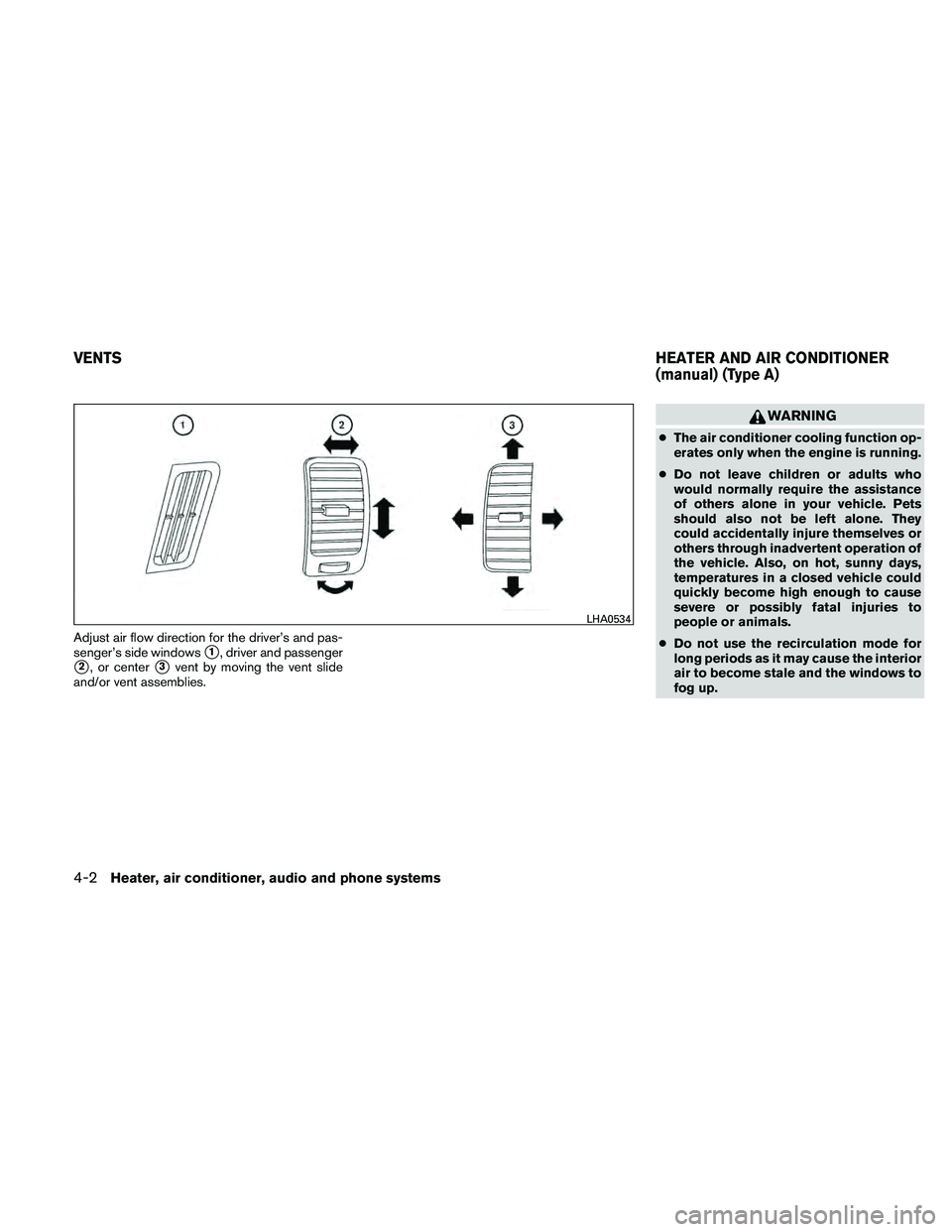
Adjust air flow direction for the driver’s and pas-
senger’s side windows
�1, driver and passenger
�2, or center�3vent by moving the vent slide
and/or vent assemblies.
WARNING
● The air conditioner cooling function op-
erates only when the engine is running.
● Do not leave children or adults who
would normally require the assistance
of others alone in your vehicle. Pets
should also not be left alone. They
could accidentally injure themselves or
others through inadvertent operation of
the vehicle. Also, on hot, sunny days,
temperatures in a closed vehicle could
quickly become high enough to cause
severe or possibly fatal injuries to
people or animals.
● Do not use the recirculation mode for
long periods as it may cause the interior
air to become stale and the windows to
fog up.
LHA0534
VENTS HEATER AND AIR CONDITIONER
(manual) (Type A)
4-2Heater, air conditioner, audio and phone systems
Page 176 of 377

5. Air recirculation button
CONTROLS
Fan control dial
The fan control dial turns the")
1. Fan control dial
2. Temperature control dial
3. Air flow control dial
4. Air conditioner button (if so equipped)
5. Air recirculation button
CONTROLS
Fan control dial
The fan control dial turns the fan on and off, and
controls fan speed.
Air flow control dial
The air flow control dial allows you to select the
air flow outlets.
MAX
A/C— Air flows from center and side
vents with maximum cooling (air
conditioning) .
— Air flows from center and sidevents.
— Air flows from center and sidevents and the front and rear floor
outlets.
— Air flows mainly from the front andrear floor outlets.
— Air flows from defroster outlets andthe front and rear floor outlets.
— Air flows mainly from defrosteroutlets.
Temperature control dial
The temperature control dial allows you to adjust
the temperature of the outlet air. To lower the
temperature, turn the dial to the left. To increase
the temperature, turn the dial to the right.
Air recirculation button
ON position:
Push the air recirculation button
to recir-
culate air inside the vehicle. The indicator light on
the
button will come on.
Push the
button to the on position:
● when driving on a dusty road.
● to prevent traffic fumes from entering pas-
senger compartment.
● for maximum cooling when using the air con-
ditioner.
Type A
WHA1384
Heater, air conditioner, audio and phone systems4-3
Page 177 of 377

OFF position:
Push the air recirculation button
again to
turn air recirculation off. The indicator light on
the
button will turn off. Outside air is drawn
into the passenger compartment and distributed
through the selected outlet.
Use the off position for normal heater or air con-
ditioner operation.
Air conditioner button
(if so equipped)
The button is provided only on vehicles equipped
with an air conditioner.
Start the engine, turn the fan control dial to the
desired (1 - 4) position and push the
button to turn on the air conditioner. The indicator
light comes on when the air conditioner is oper-
ating. To turn off the air conditioner, push
the
button again.
The air conditioner cooling function oper-
ates only when the engine is running.
HEATER OPERATION
Heating
This mode is used to direct heated air to the foot
outlets. Some air also flows from the defrost
outlets.
1. Push the
button to the OFF position
for normal heating. The indicator light on
the
button will go off.
2. Turn the air flow control dial to the
position.
3. Turn the fan control dial to the desired posi- tion.
4. Turn the temperature control dial to the de- sired position between the middle and the
hot position.
Ventilation
This mode directs outside air to the side and
center vent.
1. Push the
button to the OFF position.
The indicator light on the
button will
go off.
2. Turn the air flow control dial to the
position. 3. Turn the fan control dial to the desired posi-
tion.
4. Turn the temperature control dial to the de- sired position.
Defrosting or defogging
This mode directs the air to the defrost outlets to
defrost/defog the windows.
1. Turn the air flow control dial to the
position.
2. Turn the fan control dial to the desired posi- tion.
3. Turn the temperature control dial to the de- sired position between the middle and the
hot position.
● To quickly remove ice or fog from the win-
dows, turn the fan control dial to 4 and the
temperature control lever to the full HOT
position.
4-4Heater, air conditioner, audio and phone systems