Page 95 of 377

SUPPLEMENTAL AIR BAG
WARNING LIGHT
The supplemental air bag warning light,
displaying
in the instrument panel, moni-
tors the circuits of the supplemental front-impact
air bag, front seat-mounted side-impact supple-
mental air bag, roof-mounted curtain side-impact
and rollover supplemental air bag and seat belt
pretensioner systems. The monitored circuits in-
clude the Air bag Control Unit (ACU) , crash zone
sensor, satellite sensors, rollover sensor, occu-
pant classification sensor, front air bag modules,
side air bag modules, curtain and rollover air bag
modules, pretensioners and all related wiring. When the ignition switch is placed in the ON or
START position, the supplemental air bag warn-
ing light illuminates for about 7 seconds and then
turns off. This means the system is operational.
If any of the following conditions occur, the front
air bag, side air bag, curtain and rollover air bag
and pretensioner systems need servicing:
● The supplemental air bag warning light re-
mains on after approximately 7 seconds.
● The supplemental air bag warning light
flashes intermittently.
● The supplemental air bag warning light does
not come on at all.
Under these conditions, the front air bag, side air
bag, curtain and rollover air bag or pretensioner
systems may not operate properly. They must be
checked and repaired. Take your vehicle to the
nearest NISSAN dealer.
WARNING
If the supplemental air bag warning light
is on, it could mean that the front air bag,
side air bag, curtain and rollover air bag
and/or pretensioner systems will not op-
erate in an accident. To help avoid injury
to yourself or others, have your vehicle
checked by a NISSAN dealer as soon as
possible.
Repair and replacement procedure
The front air bags, side air bags, curtain and
rollover air bags and pretensioners are designed
to inflate on a one-time-only basis. As a reminder,
unless it is damaged, the supplemental air bag
warning light remains illuminated after inflation
has occurred. Repair and replacement of these
supplemental air bag systems should be done
only by a NISSAN dealer.
When maintenance work is required on the ve-
hicle, the front air bags, side air bags, curtain and
rollover air bags, pretensioners and related parts
should be pointed out to the person performing
the maintenance. The ignition switch should al-
ways be in the LOCK position when working
under the hood or inside the vehicle.
LRS0100
1-76Safety—Seats, seat belts and supplemental restraint system
Page 96 of 377
WARNING
●Once a front air bag, side air bag, or
curtain and rollover air bag has inflated,
the air bag module will not function
again and must be replaced. Addition-
ally, if any of the front air bags inflate,
the activated pretensioners must also
be replaced. The air bag module and
pretensioner should be replaced by a
NISSAN dealer. The air bag module and
pretensioner cannot be repaired.
● The front air bag, side air bag, curtain
and rollover air bag systems and the
pretensioner system should be in-
spected by a NISSAN dealer if there is
any damage to the front end or side
portion of the vehicle.
● If you need to dispose of a supplemen-
tal air bag or pretensioner or scrap the
vehicle, contact a NISSAN dealer. Incor-
rect disposal procedures could cause
personal injury.
Safety—Seats, seat belts and supplemental restraint system1-77
Page 97 of 377

2 Instruments and controls
Instrument panel...................................2-2
Meters and gauges ................................2-3
Speedometer and odometer .....................2-4
Tachometer ....................................2-6
Engine coolant temperature gauge ...............2-6
Fuel gauge ....................................2-7
Engine oil pressure gauge (if so equipped) ........2-8
Voltmeter (if so equipped) .......................2-8
Trip computer (if so equipped) ...................2-9
Compass and outside temperature display
(if so equipped) .................................. 2-10
Outside temperature display ....................2-10
Compass display .............................. 2-11
Warning/indicator lights and audible reminders ......2-14
Checking bulbs ............................... 2-15
Warning lights ................................ 2-15
Indicator lights ................................ 2-20
Audible reminders ............................. 2-23
Security systems (if so equipped) ..................2-24
Vehicle security system (if so equipped) ..........2-24
NISSAN vehicle immobilizer system
(if so equipped) ............................... 2-25
Windshield wiper and washer switch ...............2-26Switch operation
.............................. 2-26
Rear window and outside mirror defroster switch
(if so equipped) .................................. 2-27
Headlight and turn signal switch ....................2-28
Headlight control switch ........................ 2-28
Daytime running light system (Canada only) ......2-30
Instrument brightness control ...................2-31
Turn signal switch ............................. 2-31
Fog light switch (if so equipped) ................2-31
Hazard warning flasher switch .....................2-32
Horn ............................................ 2-32
Cargo lamp switch ............................... 2-33
Heated seat (if so equipped) .......................2-33
Vehicle Dynamic Control (VDC) off switch
(if so equipped) .................................. 2-34
Hill descent control switch (if so equipped) ..........2-34
Electronic locking rear differential (E-Lock) system
switch (if so equipped) ............................ 2-35
Clutch
interlock (clutch start) switch
(if so equipped) .................................. 2-36
Power outlet ..................................... 2-37
Storage ......................................... 2-38
Storage trays ................................. 2-38
Under-seat storage bins ........................ 2-39
Page 99 of 377
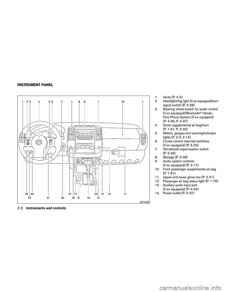
1. Vents (P. 4-2)
2. Headlight/fog light (if so equipped)/turnsignal switch (P. 2-28)
3. Steering wheel switch for audio control
(if so equipped)/Bluetooth� Hands-
Free Phone System (if so equipped)
(P. 4-35, P. 4-37)
4. Driver supplemental air bag/horn
(P. 1-61, P. 2-32)
5. Meters, gauges and warning/indicator
lights (P. 2-3, 2-14)
6. Cruise control main/set switches
(if so equipped) (P. 5-20)
7. Windshield wiper/washer switch
(P. 2-26)
8. Storage (P. 2-38)
9. Audio system controls
(if so equipped) (P. 4-17)
10. Front passenger supplemental air bag
(P. 1-61)
11. Upper and lower glove box (P. 2-41)
12. Passenger air bag status light (P. 1-70)
13. Auxiliary audio input jack
(if so equipped) (P. 4-34)
14. Power outlet (P. 2-37)
LIC1422
INSTRUMENT PANEL
2-2Instruments and controls
Page 100 of 377
15. Electronic locking rear differential(E-Lock) system switch
(if so equipped) (P. 2-35)
Heated seat switch (if so equipped)
(P. 2-33)
Hill descent control switch
(if so equipped) (P. 2-34)
Vehicle Dynamic Control (VDC) OFF
switch (if so equipped) (P. 2-34)
16. Shift selector (P. 5-13,5-17)
17. 4WD shift switch (if so equipped)
(P. 5-24)
18. Climate controls (P. 4-2, P.4-10)
19. Hazard warning flasher switch (P. 2-32)
20. Ignition switch (P. 5-10)
21. Tilt steering wheel control
(if so equipped) (P. 3-13)
22. Cargo lamp switch (P. 2-33)
23. Clutch interlock (clutch start) switch
(if so equipped) (P. 2-36)
24. Outside mirror controls
(if so equipped) (P. 3-16) 1. Warning/indicator lights
2. Tachometer
3. Speedometer
4. Fuel gauge
5. Voltmeter (if so equipped) 6. Odometer/Twin trip odometer/Trip
computer (if so equipped)
7. Engine oil pressure gauge
(if so equipped)
8. Engine coolant temperature gauge
LIC2028
METERS AND GAUGES
Instruments and controls2-3
Page 101 of 377
1. Speedometer
2. Odometer/Twin trip odometer
3. Change/Loose fuel cap warning mes-sage reset/Check tire pressure warning
message reset button
SPEEDOMETER AND ODOMETER
Speedometer
The speedometer indicates vehicle speed.
Odometer/Twin trip odometer
The odometer/twin trip odometer is displayed
when the ignition switch is placed in the ON
position.
The odometer records the total distance the ve-
hicle has been driven.
The twin trip odometer records the distance of
individual trips.
Changing the display:
For vehicles equipped with twin trip odometer,
pressing the change button changes the display
as follows:
Trip
→Trip→Trip
LIC2029
With twin trip odometer
LIC0780
2-4Instruments and controls
Page 102 of 377

For vehicles equipped with trip computer, press-
ing the change button changes the display as
follows:
Trip
→Trip→Distance to Empty →
Average speed →Average fuel consumption →
Journey time →Trip
For additional information, refer to “Trip com-
puter” later in this section.
Resetting the trip odometer:
Pushing the change button for more than 1 sec-
ond resets the currently displayed trip odometer
to zero.
Loose fuel cap warning message
Press the reset button�Afor more than 1 second
to reset the LOOSE FUEL CAP warning mes-
sage after the fuel cap has been tightened. For
additional information see “Fuel-filler cap” in the
“Pre-driving checks and adjustments” section.
Check tire pressure warning message
The CHECK TIRE PRES (pressure) warning
message is displayed when the low tire pressure
warning light is illuminated and low tire pres-
sure is detected. Check and adjust the tire pres-
sure to the recommended COLD tire pressure
shown on the Tire and Loading Information label.
The CHECK TIRE PRES warning message turns
off when the low tire pressure warning light
turns off.
Push the reset button
�Afor more than 1 second
to turn off the CHECK TIRE PRES warning mes-
sage. The low tire pressure warning light re-
mains illuminated until the tires are inflated to the
With trip computer
LIC0781LRS2004LIC2017
Instruments and controls2-5
Page 103 of 377

recommended COLD tire pressure. The CHECK
TIRE PRES warning message is displayed each
time the ignition switch is placed in the ON
position as long as the low tire pressure warning
light remains illuminated. For more information
see “Low tire pressure warning light” in the “In-
struments and controls” section, “Tire Pressure
Monitoring System (TPMS)” in the “Starting and
driving” and “Wheels and tires” section in the
“Maintenance and do-it-yourself” section of this
Owner’s Manual.
TACHOMETER
The tachometer indicates engine speed in revo-
lutions per minute (rpm) . Do not rev the engine
into the red zone
�1.
CAUTION
When engine speed approaches the red
zone, shift to a higher gear or reduce en-
gine speed. Operating the engine in the
red zone may cause serious engine
damage.
ENGINE COOLANT TEMPERATURE
GAUGE
The gauge indicates the engine coolant tempera-
ture. The engine coolant temperature is within the
normal range
�1when the gauge needle points
within the zone shown in the illustration.
The engine coolant temperature varies with the
outside air temperature and driving conditions.
LIC0738LIC0739
2-6Instruments and controls

 system switch
(if so equipped) (P. 2-35)
Heated seat switch (if so equipped)
(P. 2-33)
Hill descent control switch
(if so equipped) (P. 2-34)
Vehicle D")
