Page 133 of 377

●Use the E-Lock system only when free-
ing a stuck vehicle. Try the 4LO position
before using the E-Lock system. Never
use the E-Lock system on a slippery
road surface such as snow or ice sur-
face. Using the E-Lock system when
driving in these road conditions may
cause unexpected movement of the ve-
hicle during engine braking, accelerat-
ing or turning, which may result in an
accident and serious personal injury.
CAUTION
● After using the E-Lock system, turn the
switch OFF to prevent possible damage
to driveline components from extended
use.
● Do not drive over 12 MPH (20 km/h)
when the system is engaged. Doing so
could result in possible damage to the
driveline.
● Do not turn on the E-lock system while
the tires are spinning. Doing so could
damage drivetrain components.
WARNING
Pay special attention to your surround-
ings when using the clutch interlock
switch. The vehicle will move forward or
backward according to the gear selected.
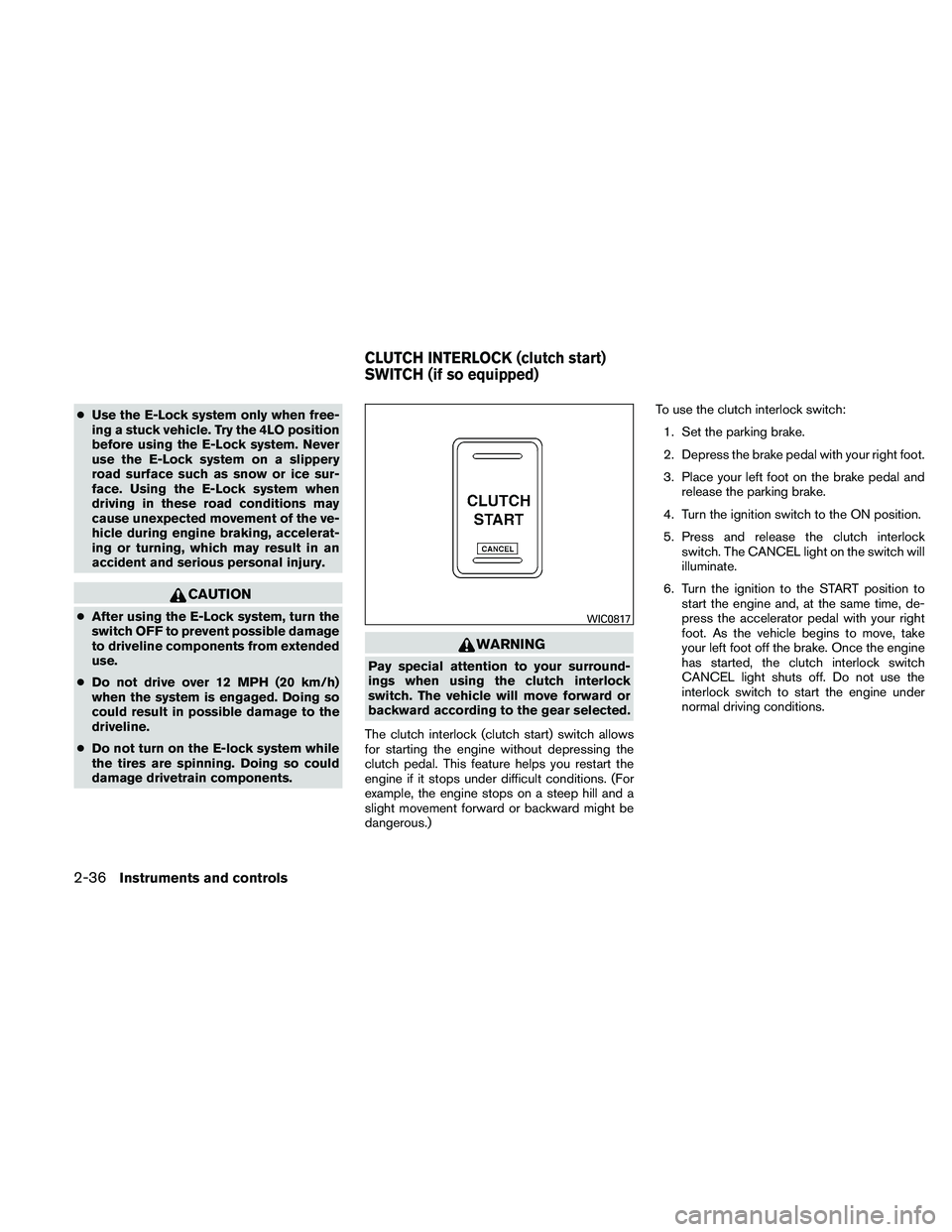
The clutch interlock (clutch start) switch allows
for starting the engine without depressing the
clutch pedal. This feature helps you restart the
engine if it stops under difficult conditions. (For
example, the engine stops on a steep hill and a
slight movement forward or backward might be
dangerous.) To use the clutch interlock switch:
1. Set the parking brake.
2. Depress the brake pedal with your right foot.
3. Place your left foot on the brake pedal and release the parking brake.
4. Turn the ignition switch to the ON position.
5. Press and release the clutch interlock switch. The CANCEL light on the switch will
illuminate.
6. Turn the ignition to the START position to start the engine and, at the same time, de-
press the accelerator pedal with your right
foot. As the vehicle begins to move, take
your left foot off the brake. Once the engine
has started, the clutch interlock switch
CANCEL light shuts off. Do not use the
interlock switch to start the engine under
normal driving conditions.
WIC0817
CLUTCH INTERLOCK (clutch start)
SWITCH (if so equipped)
2-36Instruments and controls
Page 135 of 377
STORAGE TRAYS
WARNING
Do not place sharp objects in the trays to
help prevent injury in an accident or sud-
den stop.
Top center tray
LIC1539
A/T model
LIC0818
M/T model — Type A (if so equipped)
WIC1431
STORAGE
2-38Instruments and controls
Page 137 of 377

WARNING
●Properly secure all cargo with ropes or
straps to help prevent it from sliding or
shifting. In a sudden stop or collision,
unsecured cargo could cause personal
injury.
● The cargo restrained in the under-seat
storage bins must not exceed the
weight limits listed below or the bins
may not stay secured. In a sudden stop
or collision, the unsecured bins could
cause personal inury.
King cab model: 16 lb (7.25 kg)
Crew cab model Driver’s side: 16 lb (7.25 kg)
Passenger’s side: 25 lb (11.33 kg)
● If the under-seat storage bins are re-
moved for any reason, they should be
securely stored to prevent them from
causing injury to passengers or damage
to the vehicle in case of sudden braking
or an accident.
● Do not place sharp objects in the under-
seat storage bins. Such objects may
become dangerous projectiles and
cause injury when the vehicle is moving
or if the vehicle is involved in a collision. To access the under-seat storage bins:
For King cab model, lift up the jump seat. Refer to
“Jump seat (King cab)” in the “Safety—Seats,
seat belts and supplemental restraint system”
section earlier in this manual.
For Crew cab model, lift up the rear bench seat.
Refer to “Folding the rear bench seat down” in
the “Safety—Seats, seat belts and supplemental
restraint system” section earlier in this manual.
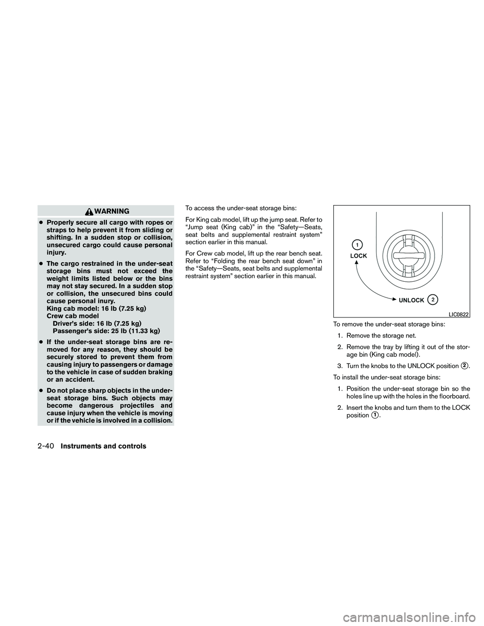
To remove the under-seat storage bins:1. Remove the storage net.
2. Remove the tray by lifting it out of the stor- age bin (King cab model) .
3. Turn the knobs to the UNLOCK position
�2.
To install the under-seat storage bins: 1. Position the under-seat storage bin so the holes line up with the holes in the floorboard.
2. Insert the knobs and turn them to the LOCK position
�1.
LIC0822
2-40Instruments and controls
Page 138 of 377
CONSOLE BOX
Pull up on the lever�1to open the console box lid
�2.
GLOVE BOX
To open the top portion of the glove box, push the
latch
�Aup and raise the lid.
To open the lower portion of the glove box, pull
the handle
�Bdown and lower the lid.
WARNING
Keep glove box lid closed while driving to
help prevent injury in an accident or a
sudden stop.
SUNGLASSES HOLDER (if so
equipped)
To open the sunglasses holder, push and release.
WARNING
● Keep the sunglasses holder closed
while driving to prevent an accident.
LIC0766LIC0768WIC0673
Instruments and controls2-41
Page 140 of 377
SEAT POCKET (if so equipped)
A pocket is located on the back of the driver’s
seat.CUP HOLDERS
The front cup holders have adapters that can be
removed to accommodate larger cups.
WARNING
The cup holder should not be used while
driving so full attention may be given to
vehicle operation.
Crew cab model
LIC0825LIC0575
Front
WIC0827
Instruments and controls2-43
Page 143 of 377

WARNING
●Drive extra carefully when the vehicle is
loaded at or near the cargo carrying
capacity, especially if the significant
portion of that load is carried on the
roof rack.
● Heavy loading of the roof rack has the
potential to affect the vehicle stability
and handling during sudden or abnor-
mal handling maneuvers.
● Roof rack load should be evenly
distributed.
● Do not exceed maximum roof rack load
weight capacity.
● Properly secure all cargo with ropes or
straps to help prevent it from sliding or
shifting. In a sudden stop or collision,
unsecured cargo could cause personal
injury.
CAUTION
Use care when placing or removing items
from the roof rack. If you cannot comfort-
ably lift the items onto the roof rack from
the ground, use a ladder or stool. Always evenly distribute the cargo on the tubular
roof rack.
The maximum total load is 125 lb
(56 kg) evenly distributed. Be careful that your
vehicle does not exceed the Gross Vehicle
Weight Rating (GVWR) or the Gross Axle
Weight Ratings (GAWR front and rear) . The
GVWR and GAWR are located on the F.M.V.S.S.
label (located on the driver’s side door jamb
pillar) . For more information regarding GVWR
and GAWR, refer to “Vehicle loading information”
in the “Technical and consumer information” sec-
tion later in this manual.
The front crossbar can be adjusted or removed.
Use the Torxdriver provided in the tool kit to
loosen both crossbar adjusting screws.
To adjust:
1. Loosen the adjusting screws with the Torxdriver
�1by turning counterclockwise
�A.
2. When the clamp is loosened, move the crossbar so the cargo can be positioned on
the crossbar
�B.
3. Tighten the crossbar adjusting screws with the Torxdriver by turning clockwise.
4. Secure the cargo with rope.
5. Always check the tightness of the crossbar adjusting screws. To remove:
1. Loosen the adjusting screws with the Torxdriver
�1by turning counterclockwise
�A.
2. Rotate the clamps
�C.
3. Remove the crossbar.
4. Reverse to install.
5. Always check the tightness of the crossbar adjusting screws.
If you hear wind noise coming from the roof rack
while driving, adjust the roof rack crossbar to the
neutral position, rearward of �on the side rails.
2-46Instruments and controls
Page 144 of 377

POWER WINDOWS (if so equipped)
WARNING
●Make sure that all passengers have
their hands, etc. inside the vehicle while
it is in motion and before closing the
windows. Use the window lock switch
to prevent unexpected use of the power
windows.
● Do not leave children unattended inside
the vehicle. They could unknowingly ac-
tivate switches or controls and become
trapped in a window. Unattended chil-
dren could become involved in serious
accidents.
The power windows operate when the ignition
switch is placed in the ON position, or for about
45 seconds after the ignition switch is placed in
the OFF position. If the driver’s or passenger’s
door is opened during this period of about 45
seconds, power to the windows is canceled.
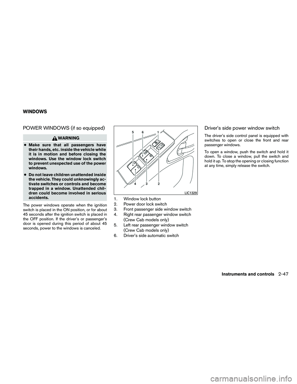
1. Window lock button
2. Power door lock switch
3. Front passenger side window switch
4. Right rear passenger window switch (Crew Cab models only)
5. Left rear passenger window switch
(Crew Cab models only)
6. Driver’s side automatic switch
Driver’s side power window switch
The driver’s side control panel is equipped with
switches to open or close the front and rear
passenger windows.
To open a window, push the switch and hold it
down. To close a window, pull the switch and
hold it up. To stop the opening or closing function
at any time, simply release the switch.
LIC1329
WINDOWS
Instruments and controls2-47
Page 147 of 377

Tilting the moonroof
Close the moonroof by pushing the switch to-
ward UP/CLOSE
�2. Release the switch, then
push the UP/CLOSE switch again to tilt the
moonroof up.
To tilt the moonroof down, push the switch to-
ward DOWN/OPEN
�1.
Restarting the moonroof sliding switch
The sliding switch will become inoperable after
the battery terminal is disconnected, the electri-
cal supply interrupted and/or some abnormality
detected. Use the following reset procedure to
return moonroof operation to normal.
1. If the moonroof lid is open, push the tilting switch repeatedly toward the
DOWN/OPEN
�1position to fully close the
lid.
2. Push and hold the tilting switch for more than 2 seconds toward the DOWN/OPEN
�1position to reestablish the lid’s home
position.
The moonroof should now operate normally.
Auto-reverse function (when closing or
tilting down the moonroof)
The auto-reverse function can be activated when
the moonroof is closed or tilted down by auto-
matic operation when the ignition switch is
placed in the ON position or for about 45 sec-
onds after the ignition switch is placed in the OFF
position.
Depending on the environment or driving
conditions, the auto-reverse function may
be activated if an impact or load similar to
something being caught in the moonroof
occurs.
WARNING
There are some small distances immedi-
ately before the closed position which
cannot be detected. Make sure that all
passengers have their hands, etc., inside
the vehicle before closing the moonroof.
When closing:
If the control unit detects something caught in the
moonroof as it moves to the front, the moonroof
will immediately open backward. When tilting down:
If the control unit detects something caught in the
moonroof as it tilts down, the moonroof will im-
mediately tilt up.
If the auto-reverse function malfunctions and re-
peats opening or tilting up the moonroof, keep
pushing the tilt down switch within 5 seconds
after it happens; the moonroof will fully close
gradually. Make sure nothing is caught in the
moonroof.
WARNING
●
In an accident you could be thrown from
the vehicle through an open moonroof.
Always use seat belts and child
restraints.
● Do not allow anyone to stand up or
extend any portion of their body out of
the moonroof opening while the vehicle
is in motion or while the moonroof is
closing.
CAUTION
● Remove water drops, snow, ice or sand
from the moonroof before opening.
● Do not place heavy objects on the
moonroof or surrounding area.
2-50Instruments and controls