Page 165 of 377
 to illumi-
nate. If the
light illuminates be-
cause the fuel-filler cap is loose or
missing, tighte")
●Failure to tighten the fuel-filler cap
properly may cause the
Mal-
function Indicator Light (MIL) to illumi-
nate. If the
light illuminates be-
cause the fuel-filler cap is loose or
missing, tighten or install the cap and
continue to drive the vehicle.
The
light should turn off after a
few driving trips. If the
light
does not turn off after a few driving
trips, have the vehicle inspected by a
NISSAN dealer.
● For additional information, see the
“Malfunction Indicator Light (MIL)” in
the “Instruments and Controls” section
in this manual.
● If fuel is spilled on the vehicle body,
flush it away with water to avoid paint
damage. To remove the fuel-filler cap:
1. Turn the fuel-filler cap counterclockwise to remove.
2. Loop the tether strap around the hook
�1
while refueling.
To install the fuel-filler cap: 1. Insert the fuel-filler cap straight into the fuel- filler tube.
2. Turn the fuel-filler cap clockwise until it clicks. The fuel-filler cap is a ratcheting type.
Loose Fuel Cap warning message
The LOOSE FUEL CAP warning message dis-
plays in the odometer when the fuel-filler cap is
not tightened correctly after the vehicle has been
refueled. To turn off the warning message, do the
following:
1. Remove and install the fuel-filler cap as de- scribed above as soon as possible.
2. Tighten the fuel-filler cap until it clicks.
3. Press the loose fuel cap warning reset but- ton
�Ain the meter for about 1 second to
turn off the LOOSE FUEL CAP warning
message after tightening the fuel-filler cap.
LPD0325LRS2004
3-12Pre-driving checks and adjustments
Page 166 of 377
For additional information, see “Meters and
gauges” in the “Instruments and Controls” sec-
tion in this manual.
TILT OPERATION (if so equipped)
Pull the lock lever forward and hold it to adjust the
steering wheel up or down to the desired posi-
tion.
Release the lock lever to lock the steering wheel
in place.
WARNING
Do not adjust the steering wheel while
driving. You could lose control of your
vehicle and cause an accident.�1To block glare from the front, swing down the
main sun visor.
�2To block glare from the side, remove the
main sun visor from the center mount and
swing the visor to the side.
LPD0304
WPD0315
STEERING WHEEL SUN VISORS
Pre-driving checks and adjustments3-13
Page 167 of 377
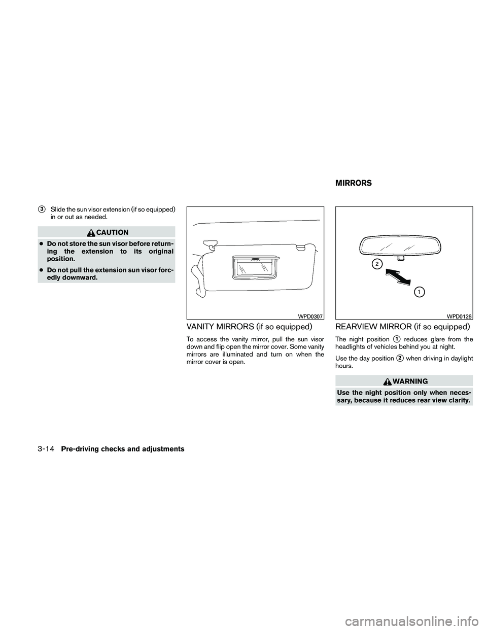
�3Slide the sun visor extension (if so equipped)
in or out as needed.
CAUTION
● Do not store the sun visor before return-
ing the extension to its original
position.
● Do not pull the extension sun visor forc-
edly downward.
VANITY MIRRORS (if so equipped)
To access the vanity mirror, pull the sun visor
down and flip open the mirror cover. Some vanity
mirrors are illuminated and turn on when the
mirror cover is open.
REARVIEW MIRROR (if so equipped)
The night position�1reduces glare from the
headlights of vehicles behind you at night.
Use the day position
�2when driving in daylight
hours.
WARNING
Use the night position only when neces-
sary, because it reduces rear view clarity.
WPD0307WPD0126
MIRRORS
3-14Pre-driving checks and adjustments
Page 168 of 377

The inside mirror is designed so that it automati-
cally dims according to the intensity of the head-
lights of the vehicle following you. The aut")
AUTOMATIC ANTI-GLARE
REARVIEW MIRROR (if so equipped)
The inside mirror is designed so that it automati-
cally dims according to the intensity of the head-
lights of the vehicle following you. The automatic
anti-glare feature operates only when the ignition
switch is in the ON position.
The indicator light
�1will illuminate when the
automatic anti-glare feature is operating.
To turn off the automatic anti-glare feature, press
the
button. The indicator light will turn off. To turn on the automatic anti-glare feature, press
the
button again. The indicator light will
turn on.
For information on HomeLink� Universal Trans-
ceiver operation, see “HomeLink� Universal
Transceiver” in the “Instruments and controls”
section of this manual.
For information on the compass and outside tem-
perature display, see “Compass and outside
temperature display” in the “Instruments and con-
trols” section of this manual.
NOTE:
Do not hang any objects over the sensors
�2or apply glass cleaner to the sensors.
Doing so will reduce the sensitivity of the
sensors, resulting in improper operation.
OUTSIDE MIRRORS
WARNING
● Objects viewed in the outside mirror on
the passenger side are closer than they
appear. Be careful when moving to the
right. Using only this mirror could cause
an accident. Use the inside mirror or
glance over your shoulder to properly
judge distances to other objects.
Manual control type (if so equipped)
The outside mirror can be moved in any direction
for a better rear view.
WPD0333WPD0170
Pre-driving checks and adjustments3-15
Page 170 of 377

For proper truck box loading see “Vehicle loading
information” in the “Technical and consumer in-
formation” section of this manual.
WARNING
●It is extremely dangerous to ride in a
cargo area inside a vehicle. In a colli-
sion, people riding in these areas are
more likely to be seriously injured or
killed.
● Do not allow people to ride in any area
of your vehicle that is not equipped with
seats and seat belts.
● Be sure everyone in your vehicle is in a
seat and using a seat belt properly.
Removing the tailgate
1. Release the tailgate support cables.
CAUTION
● The tailgate is heavy. Two people
should remove or install it. Be careful
not to drop it during removal.
● After releasing the support cables, do
not let the tailgate rest on the bumper.
2. Hold the tailgate at a 45 degree angle.
3. Pull the tailgate out from the right side hinge.
4. Slide the tailgate out of the left side hinge.
Installing the tailgate
1. Insert the tailgate into the left side hinge.
2. Hold the tailgate at a 45 degree angle and insert into the right side hinge.
3. Continue to hold the tailgate at a 45 degree angle and attach the tailgate support cables.
4. Close the tailgate securely.
LPD0271
Pre-driving checks and adjustments3-17
Page 173 of 377
WARNING
●Properly secure all cargo with ropes or
straps to help prevent it from sliding or
shifting. In a sudden stop or collision,
unsecured cargo could cause personal
injury.
3-20Pre-driving checks and adjustments
Page 175 of 377
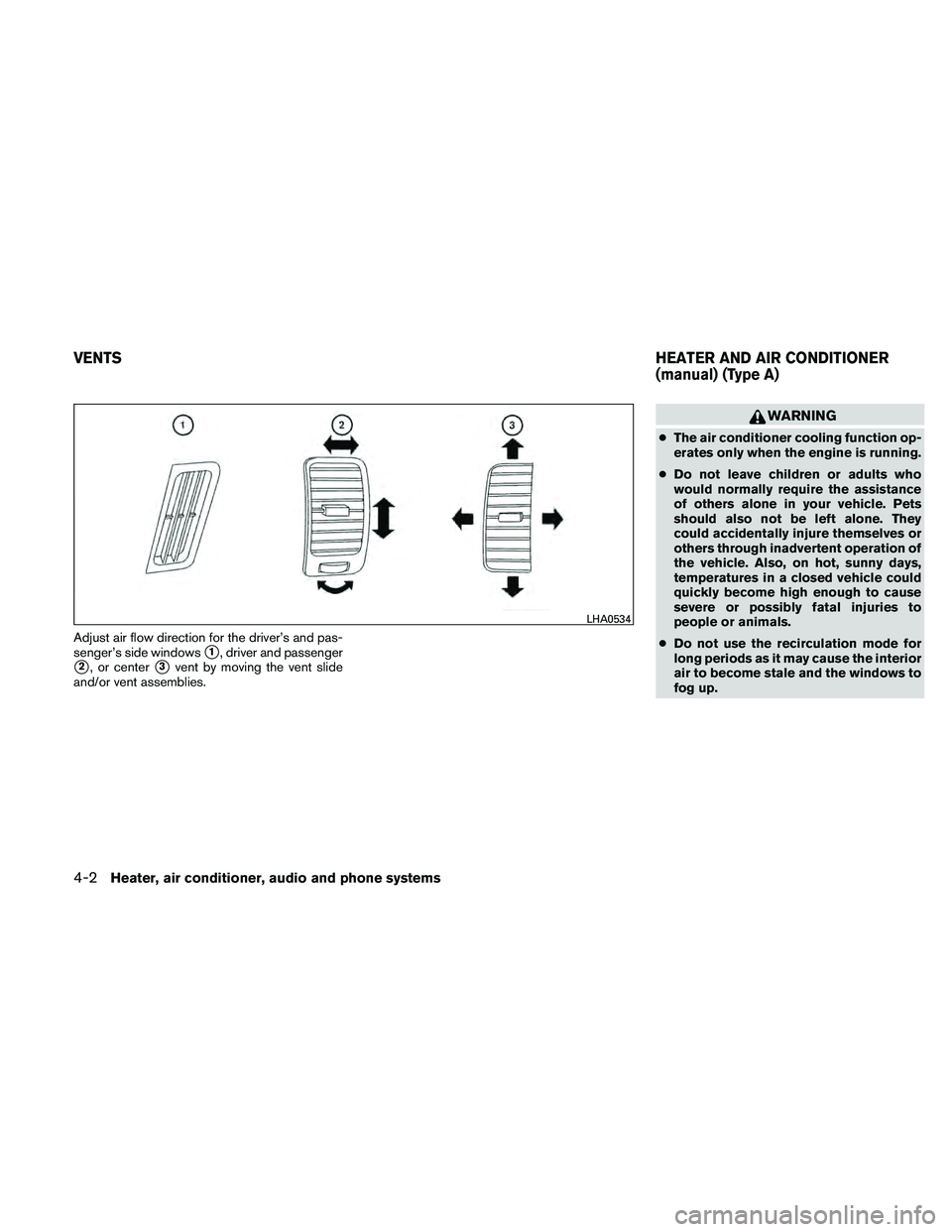
Adjust air flow direction for the driver’s and pas-
senger’s side windows
�1, driver and passenger
�2, or center�3vent by moving the vent slide
and/or vent assemblies.
WARNING
● The air conditioner cooling function op-
erates only when the engine is running.
● Do not leave children or adults who
would normally require the assistance
of others alone in your vehicle. Pets
should also not be left alone. They
could accidentally injure themselves or
others through inadvertent operation of
the vehicle. Also, on hot, sunny days,
temperatures in a closed vehicle could
quickly become high enough to cause
severe or possibly fatal injuries to
people or animals.
● Do not use the recirculation mode for
long periods as it may cause the interior
air to become stale and the windows to
fog up.
LHA0534
VENTS HEATER AND AIR CONDITIONER
(manual) (Type A)
4-2Heater, air conditioner, audio and phone systems
Page 183 of 377

WARNING
●The air conditioner cooling function op-
erates only when the engine is running.
● Do not leave children or adults who
would normally require the assistance
of others alone in your vehicle. Pets
should also not be left alone. They
could accidentally injure themselves or
others through inadvertent operation of
the vehicle. Also, on hot, sunny days,
temperatures in a closed vehicle could
quickly become high enough to cause
severe or possibly fatal injuries to
people or animals.
● Do not use the recirculation mode for
long periods as it may cause the interior
air to become stale and the windows to
fog up.
1. Fan speed control dial
2. Front window defroster button
3. Rear window defroster switch (if so
equipped)
4. Air recirculation button
5. Temperature control dial
6. Max A/C button
7. Air flow control buttons
8. Air conditioner ON/OFF buttonCONTROLS
Fan control dial
The fan control dial turns the fan on and off, and
controls fan speed.
Air flow control buttons
The air flow control buttons allow you to select
the air flow outlets.
Type B
WHA1406
HEATER AND AIR CONDITIONER
(manual) (Type B)
4-10Heater, air conditioner, audio and phone systems

Pull the lock lever forward and hold it to adjus")