2011 NISSAN 370Z ROADSTER ignition
[x] Cancel search: ignitionPage 310 of 419
Black plate (306,1)
Model "Z34-D" EDITED: 2010/ 7/ 27
The Vehicle Dynamic Control (VDC) system
uses various sensors to monitor driver inputs
and vehicle motion. Under certain driving con-
ditions, the VDC system helps to perform the
following functions.
.Controls brake pressure to reduce wheel
slip on one slipping drive wheel so power is
transferred to a non slipping drive wheel on
the same axle.
. Controls brake pressure and engine output
to reduce drive wheel slip based on vehicle
speed (traction control function) .
. Controls brake pressure at individual wheels
and engine output to help the driver maintain
control of the vehicle in the following
conditions:
— understeer (vehicle tends to not follow the steered path despite increased steering
input)
— oversteer (vehicle tends to spin due to certain road or driving conditions) .
The VDC system can help the driver to maintain
control of the vehicle, but it cannot prevent loss
of vehicle control in all driving situations.
When the VDC system operates, the VDC
warning light
in the instrument panel
flashes so note the following:
. The road may be slippery or the system may determine some action is required to help
keep the vehicle on the steered path.
. You may feel a pulsation in the brake pedal
and hear a noise or vibration from under the
hood. This is normal and indicates that the
VDC system is working properly.
. Adjust your speed and driving to the road
conditions.
See “Vehicle Dynamic Control (VDC) warning
light” in the “2. Instruments and controls”
section.
If a malfunction occurs in the system, the VDC
warning light
illuminates in the instrument
panel. The VDC system automatically turns off.
The VDC OFF switch is used to turn off the VDC
system. The VDC off indicator
illuminates
to indicate the VDC system is off. When the
VDC switch is used to turn off the system, the
VDC system still operates to prevent one drive
wheel from slipping by transferring power to a
non slipping drive wheel. The VDC warning light
flashes if this occurs. All other VDC
functions are off, and the VDC warning lightwill not flash. The VDC system is auto-
matically reset to on when the ignition switch is
placed in the off position then back to the on
position.
See “Vehicle Dynamic Control (VDC) warning
light” in the “2. Instruments and controls” section and “Vehicle Dynamic Control (VDC)
off indicator light” in the “2. Instruments and
controls” section.
The computer has a built-in diagnostic feature
that tests the system each time you start the
engine and move the vehicle forward or in
reverse at a slow speed. When the self-test
occurs, you may hear a “clunk” noise and/or feel
a pulsation in the brake pedal. This is normal and
is not an indication of a malfunction.
WARNING
.
The VDC system is designed to help
the driver maintain stability but
does not prevent accidents due to
abrupt steering operation at high
speeds or by careless or dangerous
driving techniques. Reduce vehicle
speed and be especially careful
when driving and cornering on slip-
pery surfaces and always drive care-
fully.
. Do not modify the vehicle’s suspen-
sion. If suspension parts such as
shock absorbers, struts, springs,
stabilizer bars, bushings and
wheels are not NISSAN recom-
mended for your vehicle or are
extremely deteriorated, the VDC
VEHICLE DYNAMIC CONTROL (VDC)
SYSTEM5-28
Starting and driving
Page 316 of 419
Black plate (314,1)
Model "Z34-D" EDITED: 2010/ 7/ 27
To shut off the engine in an emergency situation
while driving, perform the following procedure:
.Rapidly push the push-button ignition switch
3 consecutive times, or
. Push and hold the push-button ignition
switch for more than 2 seconds.
TIRE PRESSURE MONITORING SYS-
TEM (TPMS)This vehicle is equipped with the Tire Pressure
Monitoring System (TPMS) . It monitors tire
pressure of all tires except the spare. When
the low tire pressure warning light is lit, one or
more of your tires is significantly under-inflated.
If the vehicle is being driven with low tire
pressure, the TPMS will activate and warn you
of it by the low tire pressure warning light. This
system will activate only when the vehicle is
driven at speeds above 16 MPH (25 km/h) . For
more details, see “WARNING/INDICATOR
LIGHTS AND AUDIBLE REMINDERS” in the
“2. Instruments and controls” section and “TIRE
PRESSURE MONITORING SYSTEM (TPMS)”
in the “5. Starting and driving” section.
WARNING
.If the low tire pressure warning light
illuminates while driving, avoid sud-
den steering maneuvers or abrupt
braking, reduce vehicle speed, pull
off the road to a safe location and
stop the vehicle as soon as possi-
ble. Driving with under-inflated tires
may permanently damage the tires
and increase the likelihood of tire
failure. Serious vehicle damage could occur and may lead to an
accident and could result in serious
personal injury. Check the tire pres-
sure for all four tires. Adjust the tire
pressure to the recommended COLD
tire pressure shown on the Tire and
Loading Information label to turn
the low tire pressure warning light
OFF. If the light still illuminates
while driving after adjusting the tire
pressure, a tire may be flat. If you
have a flat tire, replace it with a
spare tire as soon as possible.
. When a spare tire is mounted or a
wheel is replaced, the TPMS will not
function and the low tire pressure
warning light will flash for approxi-
mately 1 minute. The light will
remain on after 1 minute. Contact
your NISSAN dealer as soon as
possible for tire replacement and/
or system resetting.
. Replacing tires with those not ori-
ginally specified by NISSAN could
affect the proper operation of the
TPMS.
. Do not inject any tire liquid or
aerosol tire sealant into the tires,
as this may cause a malfunction of
EMERGENCY ENGINE SHUT OFF FLAT TIRE6-2
In case of emergency
Page 325 of 419
Black plate (323,1)
Model "Z34-D" EDITED: 2010/ 7/ 27
SCE0870
5. Remove the protective cap
*A
of the hose
and screw the hose securely onto the tire
valve. Make sure that the pressure release
valve
*B
is securely tightened. Make sure
that the air compressor switch is in the OFF
( * ) position, and then insert its power plug
into the power outlet in the vehicle.
SCE0871
6. Pushtheignitionswitchtothe“ACC” position. Then turn the compressor switch
to the ON ( �) position and inflate the tire up
to the pressure that is specified on the tire
and loading information label affixed to the
driver’s side center pillar if possible, or to the
minimum of 180 kPa (26 psi) . Turn the air
compressor off briefly in order to check the
tire pressure with the pressure gauge.
If the tire is inflated to higher than the
specified pressure, lower the tire pressure
by releasing air with the pressure release
valve. NOTE:
The compressor tire pressure gauge
may show a pressure reading of 87 psi
(600 kPa) for about 30 seconds while
inflating the tire. The pressure gauge is
indicating the pressure inside the sea-
lant can. When the sealant has been
injected into the tire the pressure
gauge will drop and indicate actual tire
pressure.
WARNING
.
To avoid serious personal injury
while using the emergency tire
puncture repair kit:
— Securely tighten the compressor
hose to the tire valve. Failure to
do so can cause the sealant to
spray into the air and get into
your eyes or on the skin.
. Do not stand directly beside the
damaged tire while it is being
inflated because of the risk of the
rupture. If there are any cracks or
bumps, turn the compressor off
immediately.
If the tire pressure does not increase to 180
kPa (26 psi) within 10 minutes , the tire
In case of emergency
6-11
Page 328 of 419
Black plate (326,1)
Model "Z34-D" EDITED: 2010/ 7/ 27
SCE0791
WARNING
Always follow the instructions below.
Failure to do so could result in damage
to the charging system and cause
personal injury.
1. If the booster battery is in another vehicle*A
, position the two vehicles (
*A
and
*B)
to bring their batteries into close proximity to
each other.
Do not allow the two vehicles to touch.
2. Apply parking brake. Move the selector lever to the P (Park) position (Automatic transmis- sion models) . Move the shift lever to the N
(Neutral) position (Manual transmission
models) . Switch off all unnecessary elec-
trical systems (light, heater, air conditioner,
etc.) .
3. Remove vent caps on the battery (if so equipped) . Cover the battery with a firmly
wrung out moist cloth
*C
to reduce
explosion hazard.
4. Connect jumper cables in the sequence as illustrated (
*1
?
*2
?
*3
?
*4).
For models with a steering wheel lock
mechanism: If the battery is discon-
nected or discharged, the steering wheel will lock and cannot be turned.
Supply power using jumper cables
before pushing the ignition switch and
disengaging the steering lock.
CAUTION
.
Always connect positive (+) to posi-
tive (+) and negative ( �) to body
ground (as illustrated) — not to the
battery.
. Make sure the jumper cables do not
touch moving parts in the engine
compartment and that clamps do
not contact any other metal.
5. Start the engine of the booster vehicle
*A
and let it run for a few minutes.
6. Keep the engine speed of the booster vehicle
*A
at about 2,000 rpm, and start
the engine of the vehicle being jump started
*B.
CAUTION
Do not keep the starter motor engaged
for more than 10 seconds. If the engine
does not start right away, push the
ignition switch to the OFF position
and wait 10 seconds before trying
6-14
In case of emergency
Page 331 of 419
Black plate (329,1)
Model "Z34-D" EDITED: 2010/ 7/ 27
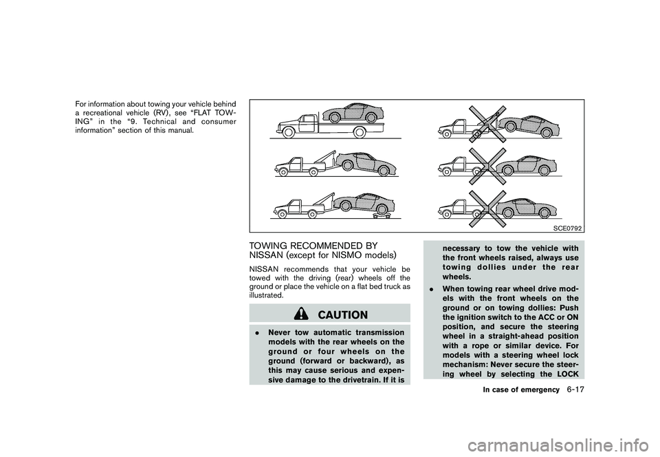
For information about towing your vehicle behind
a recreational vehicle (RV) , see “FLAT TOW-
ING” in the “9. Technical and consumer
information” section of this manual.
SCE0792
TOWING RECOMMENDED BY
NISSAN (except for NISMO models)NISSAN recommends that your vehicle be
towed with the driving (rear) wheels off the
ground or place the vehicle on a flat bed truck as
illustrated.
CAUTION
.Never tow automatic transmission
models with the rear wheels on the
ground or four wheels on the
ground (forward or backward) , as
this may cause serious and expen-
sive damage to the drivetrain. If it is necessary to tow the vehicle with
the front wheels raised, always use
towing dollies under the rear
wheels.
. When towing rear wheel drive mod-
els with the front wheels on the
ground or on towing dollies: Push
the ignition switch to the ACC or ON
position, and secure the steering
wheel in a straight-ahead position
with a rope or similar device. For
models with a steering wheel lock
mechanism: Never secure the steer-
ing wheel by selecting the LOCK
In case of emergency
6-17
Page 332 of 419
Black plate (330,1)
Model "Z34-D" EDITED: 2010/ 7/ 27
position. This may damage the
steering lock mechanism.
. If you have to tow manual transmis-
sion models with the rear wheels on
the ground (if you do not use towing
dollies) or four wheels on the
ground:
— Push the ignition switch to the
ON position and turn off all
accessories.
— Always release the parking brake.
— Move the transmission shift le- ver to the N (Neutral) position.
— Observe the following restricted towing speeds and distances for
manual transmission models
only:
.
Rear wheels on the ground:
Speed: Below 50 MPH (80
km/h)
Distance: Less than 50 miles
(80 km)
.
Four wheels on the ground:Speed: Below 70 MPH (112
km/h)
Distance: Less than 500 miles
(800 km)
— If the speed or distance must necessarily be greater, remove
the propeller shaft before tow-
ing to prevent damage to the
drivetrain.
6-18
In case of emergency
Page 349 of 419
Black plate (349,1)
Model "Z34-D" EDITED: 2010/ 7/ 27
When performing any inspection or mainte-
nance work on your vehicle, always take care
to prevent serious accidental injury to yourself or
damage to the vehicle. The following are general
precautions which should be closely observed.
WARNING
.Park the vehicle on a level surface,
apply the parking brake securely
and block the wheels to prevent
the vehicle from moving. For man-
ual transmission models, move the
shift lever to N (Neutral) . For auto-
matic transmission models, move
the selector lever to P (Park) .
. Be sure the ignition switch is in the
OFF or LOCK position when per-
forming any parts replacement or
repairs.
. Never connect or disconnect the
battery or any transistorized com-
ponent while the ignition switch is
in the ON position.
. Never leave the engine or automatic
transmission related component
harnesses disconnected while the
ignition switch is in the ON position.
. If you must work with the engine running, keep your hands, clothing,
hair and tools away from moving
fans, belts and any other moving
parts.
. It is advisable to secure or remove
any loose clothing and remove any
jewelry, such as rings, watches, etc.
before working on your vehicle.
. Always wear eye protection when-
ever you work on your vehicle.
. If you must run the engine in an
enclosed space such as a garage, be
sure there is proper ventilation for
exhaust gases to escape.
. Never get under the vehicle while it
is supported only by a jack. If it is
necessary to work under the vehicle,
support it with safety stands.
. Keep smoking materials, flame and
sparks away from fuel tank and the
battery.
. Your vehicle is equipped with an
automatic engine cooling fan. It may
come on at any time without warn-
ing, even if the ignition key is in the
OFF position and the engine is not
running. To avoid injury, always
disconnect the negative battery cable before working near the fan.
. The fuel filter or fuel lines should be
serviced by a NISSAN dealer be-
cause the fuel lines are under high
pressure even when the engine is
off.
CAUTION
.Do not work under the hood while
the engine is hot. Turn the engine
off and wait until it cools down.
. Avoid direct contact with used en-
gine oil and coolant. Improperly
disposed engine oil, coolant, and/
or other vehicle fluids can damage
the environment. Always conform to
local regulations for disposal of
vehicle fluid.
This “8. Maintenance and do-it-yourself” section
gives instructions regarding only those items
which are relatively easy for an owner to perform.
A genuine NISSAN Service Manual is also
available. (See “OWNER’S MANUAL/SERVICE
MANUAL ORDER INFORMATION” in the “9.
Technical and consumer information” section.)
Youshouldbeawarethatincompleteor
MAINTENANCE PRECAUTIONS
Maintenance and do-it-yourself
8-5
Page 361 of 419
Black plate (361,1)
Model "Z34-D" EDITED: 2010/ 7/ 27
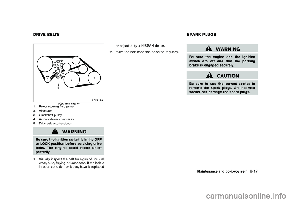
SDI2119
VQ37VHR engine
1. Power steering fluid pump
2. Alternator
3. Crankshaft pulley
4. Air conditioner compressor
5. Drive belt auto-tensioner
WARNING
Be sure the ignition switch is in the OFF
or LOCK position before servicing drive
belts. The engine could rotate unex-
pectedly.
1. Visually inspect the belt for signs of unusual wear, cuts, fraying or looseness. If the belt is
in poor condition or loose, have it replaced or adjusted by a NISSAN dealer.
2. Have the belt condition checked regularly.
WARNING
Be sure the engine and the ignition
switch are off and that the parking
brake is engaged securely.
CAUTION
Be sure to use the correct socket to
remove the spark plugs. An incorrect
socket can damage the spark plugs.
DRIVE BELTS SPARK PLUGS
Maintenance and do-it-yourself
8-17