2011 MITSUBISHI PAJERO IV low beam
[x] Cancel search: low beamPage 88 of 377

Indication and warning lamps
E005015020861-
Turn-signal indication lamps/Hazard warning indication lamps ® p. 3-08
2- Rear fog lamp indication lamp
® p. 3-08
3- Position lamp indication lamp ® p. 3-08
4- Front fog lamp indication lamp* ® p. 3-08
5- Automatic headlamp levelling warning lamp* ® p. 3-34
6- High-beam indication lamp ® p. 3-08
7- Active stability control function OFF indication lamp ® p. 4-43
8- Active stability control function indication lamp/Active traction control func-
tion indication lamp ® p. 4-43, 4-44
9- Anti-lock brake system (ABS) warning lamp ® p. 4-40
10- Brake warning lamp ® p. 3-09
11- Supplement Restraint System (SRS) warning lamp ® p. 2-43
12- Seat belt warning lamp ® p. 2-21
13- A/T fluid temperature warning lamp (vehicles with A/T) ® p. 4-22
14- CRUISE indication lamp* ® p. 4-45 15-
“SONAR OFF” indication lamp* ® p. 4-52
16- Diesel particulate filter (DPF) warning lamp* ®
p. 4-15
17- Diesel preheat indication lamp (diesel-powered vehicles) ® p. 3-08
18- Fuel filter indication lamp (diesel-powered vehicles) ® p. 3-08
19- Check engine warning lamp ® p. 3-10
20- Charge warning lamp ® p. 3-10
21- Oil pressure warning lamp ® p. 3-10
22- Low fuel warning lamp ® p. 3-05
23- 2WD/4WD operation indication lamp ® p. 4-26
24- The rear differential lock indication lamp* ® p. 4-29
25- Door ajar warning lamp ® p. 3-11
26- Service reminder ® p. 3-03
27- Sports mode indicator (vehicles with A/T) ® p. 4-21
28- Selector lever position indication lamps (vehicles with A/T, “N” indication
lamp is used also as A/T warning lamp) ® p. 4-20 Instruments and controls
3-07 3
OBKE12E1
Page 89 of 377

Indication lamps
E00501600012Turn-signal indication lamps/
Hazard warning indication
lamps
E00501700068
These indication lamps
blink on and off
when a turn-signal lamp is operating.
NOTE
l If the blinking is too fast, the
cause may be a blown lamp bulb
or a faulty turn-signal connection.
When the hazard warning lamp switch is
pressed, all turn-signal lamps will flash
on and off continuously. High-beam indication lamp
E00501800072
This indication lamp
illuminates when
the high-beam is used. Front fog lamp indication
lamp*
E00501900132
This indication lamp
illuminates while
the front fog lamps are on. Rear fog lamp indication lamp
E00502000084
This lamp illuminates
while the rear fog
lamp is on. Position lamp indication lamp
E00508900102
This lamp illuminates
with the lamp
switch at “ ” or “ ” position
Diesel preheat indication lamp
(diesel-powered vehicles)
E00502300146
This indication lamp
illuminates when
the ignition switch is placed in the “ON”
position. As the glow plug becomes hot,
the lamp goes out and the engine can be
started. CAUTION
l
If the
diesel
preheat indication
lamp comes on after the engine
is started, the engine speed may
not rise above the idling speed
because of fuel freezing. In this
case, keep the engine idling for
about ten minutes, then turn
off the ignition switch and im-
mediately turn it on again to
confirm that the diesel preheat
indication lamp is off.
NOTE l If
the engine
is cold, the diesel pre-
heat indication lamp is on for a lon-
ger time. l
When the
engine
has not been star-
ted within about 5 seconds after
the diesel preheat indication lamp
went out, return the ignition
switch to the “LOCK” position.
Then, turn the switch to the “ON”
position to preheat the engine
again.
l When the engine is warm, the die-
sel preheat indication lamp does
not come on even if the ignition
switch is placed in the “ON” posi-
tion. Fuel filter indication lamp (die-
sel-powered vehicles)
E00509900239
This indication lamp
illuminates when
the ignition switch is turned to the “ON”
position and goes off after the engine
has started. If it lights up while the en-
gine is running, it indicates that water
has accumulated inside the fuel filter; if
this happens, remove the water from the
fuel filter. Refer to “Removal of water
from the fuel filter (diesel-powered vehi-
cles only)” on page 6-06.
When the lamp goes out, you can re-
sume driving. If it either does not go out
or comes on from time to time, we rec-
ommend you to have the vehicle inspec-
ted. Instruments and controls
3-08
3
OBKE12E1
Page 113 of 377

Daytime running lamp*
When the ignition
switch is in the “ON” position
and the lamp switch is set to the “OFF” position,
the low beam of the headlamps, tail lamps, etc.,
will illuminate.
Lamps (headlamps, fog lamp, etc.) au-
to-cutout function E00532700178
l If the ignition
key is turned to the “LOCK”
or “ACC” position or removed from the igni-
tion switch, and without opening the driver’s
door for 3 minutes with the lamp switch in
the “ ” position, the lamps will turn off au-
tomatically.
l If the
ignition
key is turned to the “LOCK”
or “ACC” position or removed from the igni-
tion switch and the driver’s door is opened
within 3 minutes with the lamp switch in the
“ ” position, a buzzer will sound to warn
the driver
that the lamps have not been
turned off, and these lamps will automatical-
ly turn off.
NOTE l The lamp auto-cutout will not function when
the lamp switch is in the “ ” position
l When the
ignition
key has been turned to ei-
ther the “LOCK” or “ACC” position or re-
moved from the ignition switch with the
lamp switch in the “ ” position, and the
lamp switch
is returned to the “OFF” within
approximately 3 minutes, the auto-cutout
function will not be activated. When you want to keep the lamps on:
l Turn the
lamp
switch in the “OFF” position
while the ignition switch is in the “LOCK”
or “ACC” position.
l Turn on the lamps with the switch in the
“ ” or “ ” position again, then the
lamps will remain on.
l Remove the ignition key.
NOTE l For further
information, we recommend you
to consult a MITSUBISHI MOTORS Author-
ized Service Point.
Lamp monitor buzzer E00506100256
If the driver’s door is opened when the key is in the
“LOCK” or “ACC”
position or removed from the
ignition switch while the lamps are on, a buzzer
will sound to remind the driver to turn off the lamps.
When the lamp auto-cutout function acts, the buz-
zer will stop automatically. Dipper (High/Low beam change)
E00506200055
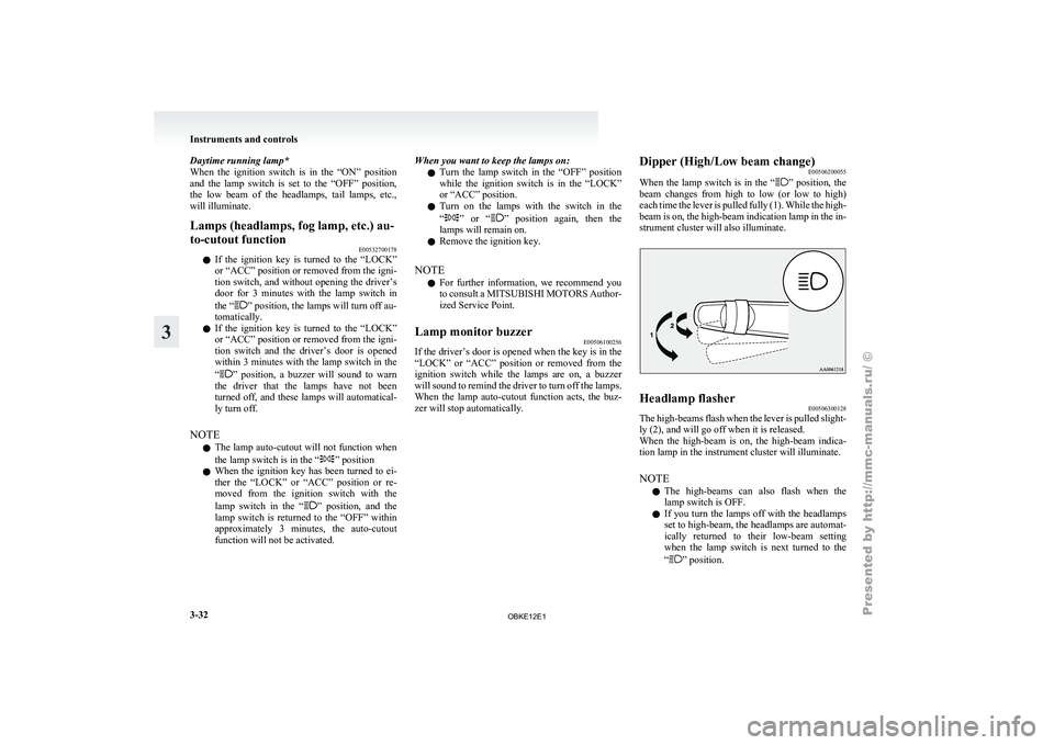
When the lamp
switch is in the “ ” position, the
beam changes
from high to low (or low to high)
each time the lever is pulled fully (1). While the high-
beam is on, the high-beam indication lamp in the in-
strument cluster will also illuminate. Headlamp flasher
E00506300128
The high-beams flash when the lever is pulled slight-
ly (2), and will go off when it is released.
When the high-beam
is on, the high-beam indica-
tion lamp in the instrument cluster will illuminate.
NOTE
l The high-beams can also flash when the
lamp switch is OFF.
l If you turn the lamps off with the headlamps
set to high-beam, the headlamps are automat-
ically returned to their low-beam setting
when the lamp switch is next turned to the
“ ” position.Instruments and controls
3-32
3
OBKE12E1
Page 114 of 377

Headlamp levelling
E00517400015
Headlamp levelling switch* E00517500553
Except for vehicles with discharge headlamps
The angle of the headlamp beam varies depending
on the load carried by the vehicle.
The headlamp levelling dial can be used to adjust
the headlamp illumination distance (when the low-
er beam is illuminated) so that the headlamps’
glare does not distract other drivers.
Set the dial according to the following table.
LHD
RHD CAUTION
l
Always perform adjustments
before driv-
ing.
Do not attempt to adjust while driving, as
it could cause an accident.
NOTE l When
adjusting the
beam position, first put
the dial in the “0” position (the highest beam
position).
3-door models
Except for vehicles with only the front seats Vehi-
cle
condi- tion Switch
posi-tion “0” “0” “2” “3”
or“4”“4” ●: 1 person
: Full luggage loadingSwitch position 0- Driver only/
Driver + 1 front passenger
Switch position 2- 5 passengers (including driver)
Switch position 3- 5 passengers (including driver) + Full
luggage load-
ing
{Except for vehicles for
Russia, Ukraine and Ka-
zakhstan}
Switch position 4- 5 passengers (including driver) + Full
luggage load-
ing
{Vehicles for Russia, Uk-
raine and Kazakhstan}
Driver + Full luggage load-
ing
Vehicles with only the front seats Vehicle condi-
tion Switch position “0”
“4” ●: 1 person
: Full luggage loading
Switch position 0- Driver only
Switch position 4- Driver + Full luggage load- ing Instruments and controls
3-33 3
OBKE12E1
Page 137 of 377

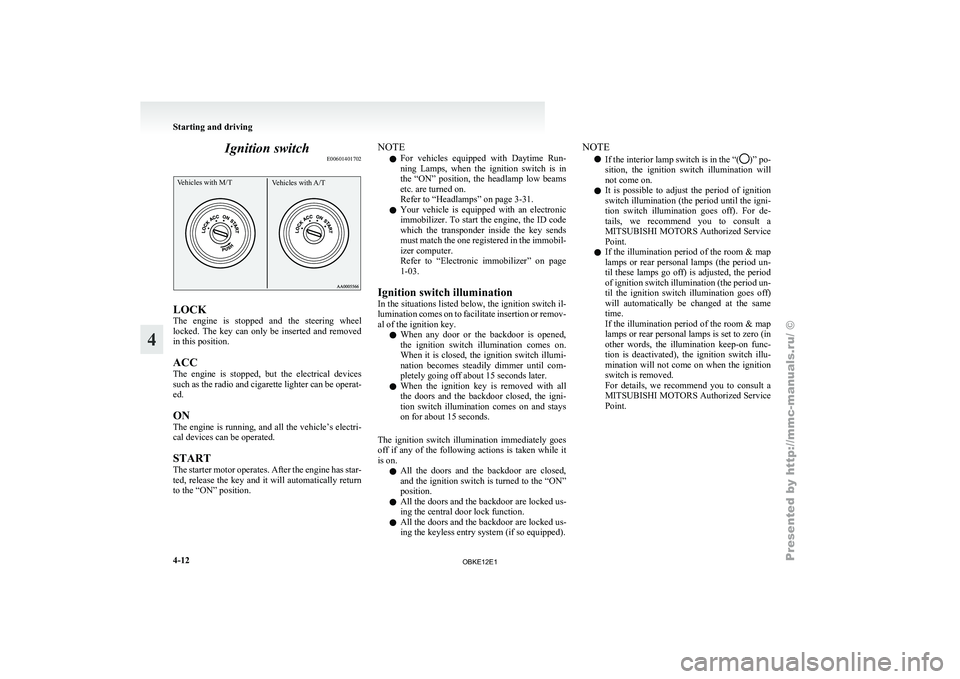
Ignition switch
E00601401702Vehicles with M/T Vehicles with A/TLOCK
The
engine is
stopped and the steering wheel
locked. The key can only be inserted and removed
in this position.
ACC
The engine is stopped, but the electrical devices
such as the radio and cigarette lighter can be operat-
ed.
ON
The engine is running, and all the vehicle’s electri-
cal devices can be operated.
START
The starter motor operates. After the engine has star-
ted, release the key and it will automatically return
to the “ON” position. NOTE
l For
vehicles equipped
with Daytime Run-
ning Lamps, when the ignition switch is in
the “ON” position, the headlamp low beams
etc. are turned on.
Refer to “Headlamps” on page 3-31.
l Your vehicle is equipped with an electronic
immobilizer. To start the engine, the ID code
which the transponder inside the key sends
must match the one registered in the immobil-
izer computer.
Refer to “Electronic immobilizer” on page
1-03.
Ignition switch illumination
In the situations listed below, the ignition switch il-
lumination comes on to facilitate insertion or remov-
al of the ignition key. l When any door or the backdoor is opened,
the ignition switch illumination comes on.
When it is closed, the ignition switch illumi-
nation becomes steadily dimmer until com-
pletely going off about 15 seconds later.
l When the ignition key is removed with all
the doors and the backdoor closed, the igni-
tion switch illumination comes on and stays
on for about 15 seconds.
The ignition switch illumination immediately goes
off if any of the following actions is taken while it
is on. l All the doors and the backdoor are closed,
and the ignition switch is turned to the “ON”
position.
l All the doors and the backdoor are locked us-
ing the central door lock function.
l All the doors and the backdoor are locked us-
ing the keyless entry system (if so equipped). NOTE
l If the interior
lamp switch is in the “( )” po-
sition, the ignition
switch illumination will
not come on.
l It is possible to adjust the period of ignition
switch illumination (the period until the igni-
tion switch illumination goes off). For de-
tails, we recommend you to consult a
MITSUBISHI MOTORS Authorized Service
Point.
l If the illumination period of the room & map
lamps or rear personal lamps (the period un-
til these lamps go off) is adjusted, the period
of ignition switch illumination (the period un-
til the ignition switch illumination goes off)
will automatically be changed at the same
time.
If the illumination period of the room & map
lamps or rear personal lamps is set to zero (in
other words, the illumination keep-on func-
tion is deactivated), the ignition switch illu-
mination will not come on when the ignition
switch is removed.
For details, we recommend you to consult a
MITSUBISHI MOTORS Authorized Service
Point. Starting and driving
4-12
4
OBKE12E1
Page 329 of 377

No. Symbol Electrical sys-
tem Capacity
21 — — —
22 Windscreen
wiper 20 A
23 Tail lamp (right) 7.5 A
24 Tail lamp (left) 7.5 A
25 Headlamp low
beam (right) 10 A
*2
20 A *3
26 Headlamp low
beam (left) 10 A
*2
20 A *3
27 Headlamp high-
beam (right) 10 A
28 Headlamp high-
beam (left) 10 A
29 Audio
30 A*1
30 Heater
50 A*1
*1 : Fusible link
*2 : Vehicles without discharge headlamps
*3 : Vehicles with discharge headlamps l
Some fuses
may not be installed on your ve-
hicle, depending on the vehicle model or spec-
ifications. l
The
table above
shows the main equipment
corresponding to each fuse.
Engine compartment fuse location (Type B) No. Symbol Electrical sys-
tem Capacity
31 Anti-lock brake
system
60 A
*
32 Brake system
40 A*
33 Glow relay
80 A*
* : Fusible link l
Some fuses
may
not be installed on your ve-
hicle, depending on the vehicle model or spec-
ifications.
l The table above shows the main equipment
corresponding to each fuse.
Identification of fuse E01008100164 Capacity Colour
7.5 A Brown Capacity Colour
10 A Red
15 A Blue
20 A Yellow (fuse type)/Light blue (fusible link type)
25 A Transparent
30 A Green (fuse type)/
Pink (fusible link type)
40 A Green
50 A Red
60 A Yellow
80 A Black
140 A Reddish brown Fuse replacement
E01007800702
1. Before replacing a fuse, always turn off the
electrical circuit
concerned and place the ig-
nition switch in the “LOCK” position.
2. Pull the fuse block lid (A) to remove it.
3. Remove the fuse puller (B) from the fuse block lid. Maintenance
8-22
8
OBKE12E1
Page 331 of 377

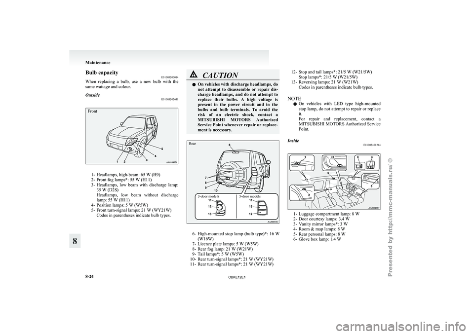
Bulb capacity
E01003200014
When replacing a
bulb, use a new bulb with the
same wattage and colour.
Outside E01003302631
Front1- Headlamps, high-beam: 65 W (H9)
2- Front fog lamps*: 55 W (H11)
3-
Headlamps,
low beam with discharge lamp:
35 W (D2S)
Headlamps, low beam without discharge
lamp: 55 W (H11)
4- Position lamps: 5 W (W5W)
5- Front turn-signal lamps: 21 W (WY21W) Codes in parentheses indicate bulb types. CAUTION
l
On vehicles with discharge headlamps, do
not attempt to
disassemble or repair dis-
charge headlamps, and do not attempt to
replace their bulbs. A high voltage is
present in the power circuit and in the
bulbs and bulb terminals. To avoid the
risk of an electric shock, contact a
MITSUBISHI MOTORS Authorized
Service Point whenever repair or replace-
ment is necessary.
3-door models 5-door models
Rear
6- High-mounted stop
lamp
(bulb type)*: 16 W
(W16W)
7- Licence plate lamps: 5 W (W5W)
8- Rear fog lamp: 21 W (W21W)
9- Tail lamps*: 5 W (W5W)
10- Rear turn-signal lamps*: 21 W (WY21W)
11- Rear turn-signal lamps*: 21 W (WY21W) 12- Stop and tail lamps*: 21/5 W (W21/5W)
Stop lamps*: 21/5 W (W21/5W)
13- Reversing lamps: 21 W (W21W) Codes in parentheses indicate bulb types.
NOTE l On
vehicles
with LED type high-mounted
stop lamp, do not attempt to repair or replace
it.
For repair and replacement, contact a
MITSUBISHI MOTORS Authorized Service
Point.
Inside E01003401244 1- Luggage compartment lamp: 8 W
2- Door courtesy lamps: 3.4 W
3-
Vanity mirror lamps*:
3 W
4- Room & map lamps: 8 W
5- Rear personal lamps: 8 W
6- Glove box lamp: 1.4 W Maintenance
8-24
8
OBKE12E1
Page 332 of 377

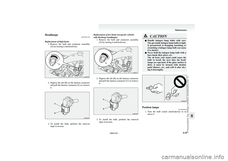
Headlamps
E01003501199
Replacement of high-beam 1. Remove the bulb
and connector assembly
(A) by turning it anticlockwise. 2. Depress the tab (B) on the harness connector
and pull
the harness connector (C) to remove
it. 3. To
install the bulb, perform the removal
steps in reverse. Replacement of low beam (except for vehicles
with discharge headlamps)
1.Remove the bulb
and connector assembly
(A) by turning it anticlockwise. 2. Depress the tab (B) on the harness connector
and pull
the harness connector (C) to remove
it. 3. To install the bulb, perform the removal
steps in reverse. CAUTION
l
Handle halogen lamp
bulbs with care.
The gas inside halogen lamp bulbs is high-
ly pressurized, so dropping, knocking, or
scratching a halogen lamp bulb can cause
it to shatter.
l Never hold the halogen lamp bulb with a
bare hand, dirty glove, etc.
The oil from your hand could cause the
bulb to break the next time the head-
lamps are operated. If the glass surface is
dirty, it must be cleaned with alcohol,
paint thinner, etc., and refit it after dry-
ing it thoroughly. Position lamps
E01003700471
1. Turn the bulb socket anticlockwise to re-
move it. Maintenance
8-25 8
OBKE12E1