Page 342 of 514
Comfort controls
5-23
5
NOTE�Set the temperature {at about 75 (Type 1) or 25 (Type 2)
under normal conditions}.
�When the temperature is set to the highest or the lowest
setting under the AUTO operation, the air selection and
the air conditioning will be automatically changed as fol-
lows.
• Quick Heating (When the temperature is set to the high-
est setting)
Outside air will be introduced and the air conditioning
will stop.
• Quick Cooling (When the temperature is set to the low-
est setting)
Inside air will be recirculated and the air conditioning
will operate.
�When the temperature is set to the highest setting, you can
turn the air conditioning on.
Operating the air conditioning system (manual
mode)
N00731800027
Blower speed and vent mode may be controlled manually by
setting the blower speed selection dial and the mode selection
dial to the desired positions. To return to automatic operation,
set the dials to the “AUTO” position.Defrosting or defogging the windshield and door win-
dows
N00732400310
To remove frost or fog from the windshield and door windows,
use the mode selection dial (“ ” or “ ”).
CAUTION
!�For safety, make sure you have a clear view through
all the windows.
BK0121600US.book 23 ページ 2010年4月12日 月曜日 午前10時39分
Page 343 of 514
5-24 Comfort controls
5
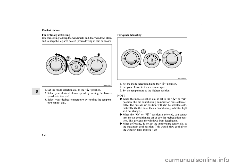
For ordinary defrosting
Use this setting to keep the windshield and door windows clear,
and to keep the leg area heated (when driving in rain or snow).
1. Set the mode selection dial to the “ ” position.
2. Select your desired blower speed by turning the blower
speed selection dial.
3. Select your desired temperature by turning the tempera-
ture control dial.For quick defrosting
1. Set the mode selection dial to the “ ” position.
2. Set your blower to the maximum speed.
3. Set the temperature to the highest position.
NOTE�When the mode selection dial is set to the “ ” or “ ”
position, the air conditioning compressor runs automati-
cally. The outside air position will also be selected auto-
matically. (In this case, the air conditioning indicator light
will not change.)
�When the “ ” or “ ” position is selected, you cannot
turn the air conditioning off or use the recirculation posi-
tion. This prevents the windows from fogging up.
�When defrosting, do not set the temperature control dial to
the maximum cool position. This would blow cool air on
the window glass and fog it up.
BK0121600US.book 24 ページ 2010年4月12日 月曜日 午前10時39分
Page 344 of 514
Comfort controls
5-25
5
To stop the air conditioning
N00732500021
To turn the air conditioning off, set the blower speed selection
dial to the “OFF” position. All operations will stop except the
air selection.
Rear cooler (For vehicles with automatic
air conditioning)
N00737400038
The rear cooler can only be used while the operation indicator
light (A) illuminates. The operation indicator light illuminates
when the mode selection dial is set to the “ ” or “ ” posi-
tion.
BK0121600US.book 25 ページ 2010年4月12日 月曜日 午前10時39分
Page 345 of 514
5-26 Comfort controls
5
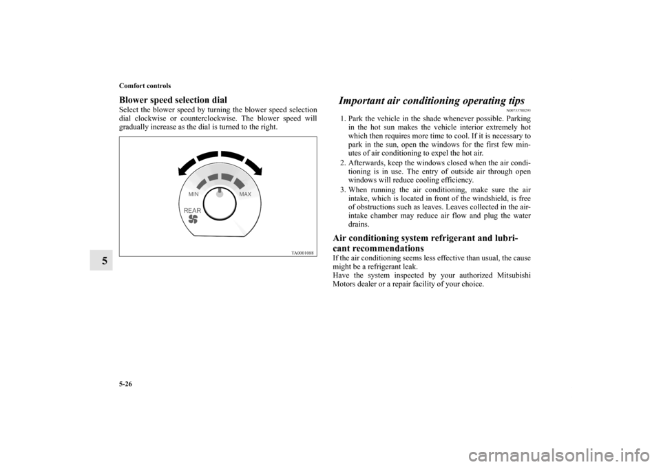
Blower speed selection dialSelect the blower speed by turning the blower speed selection
dial clockwise or counterclockwise. The blower speed will
gradually increase as the dial is turned to the right.
Important air conditioning operating tips
N00733700293
1. Park the vehicle in the shade whenever possible. Parking
in the hot sun makes the vehicle interior extremely hot
which then requires more time to cool. If it is necessary to
park in the sun, open the windows for the first few min-
utes of air conditioning to expel the hot air.
2. Afterwards, keep the windows closed when the air condi-
tioning is in use. The entry of outside air through open
windows will reduce cooling efficiency.
3. When running the air conditioning, make sure the air
intake, which is located in front of the windshield, is free
of obstructions such as leaves. Leaves collected in the air-
intake chamber may reduce air flow and plug the water
drains. Air conditioning system refrigerant and lubri-
cant recommendations If the air conditioning seems less effective than usual, the cause
might be a refrigerant leak.
Have the system inspected by your authorized Mitsubishi
Motors dealer or a repair facility of your choice.
BK0121600US.book 26 ページ 2010年4月12日 月曜日 午前10時39分
Page 346 of 514
Comfort controls
5-27
5
During a long period of disuse The air conditioning should be operated for at least five min-
utes each week, even in cold weather. This includes the quick
defrosting mode. Operating the air condition system weekly
maintains lubrication of the compressor internal parts and
maintains the air conditioning in the best operating condition.
CAUTION
!�The air conditioning system in your vehicle must be
charged with the refrigerant HFC-134a and the
lubricant SUN-PAG56.
Use of any other refrigerant or lubricant will cause
severe damage and may require replacing your vehi-
cle’s entire air conditioning system.
The release of refrigerant into the atmosphere is not
recommended.
The new refrigerant HFC-134a in your vehicle is
designed not to harm the earth’s ozone layer. How-
ever, it may contribute slightly to global warming.
It is recommended that the old refrigerant be saved
and recycled for future use.
BK0121600US.book 27 ページ 2010年4月12日 月曜日 午前10時39分
Page 460 of 514
Vehicle care and maintenance
7-33
7 General maintenance
N00941500159
The next pages list the maintenance service recommended by
Mitsubishi Motors Corporation. In addition to the general
maintenance that needs to be performed at the times listed,
there are other parts which do not usually need regular mainte-
nance.
But, if any of these parts stops working properly, your vehicle
performance could suffer. Have these items checked if you
notice a problem with them.
See your authorized Mitsubishi Motors dealer for assistance, if
you have any questions.Disc brake pads
N00941600020
Good brakes are essential to safe driving. Check the brake pads
for wear. For good braking performance, replace the brake pads
with the same type pads as the originals.Brake hoses
N00941700089
Brake hoses and tubing should be checked for:
�Severe surface cracking, scuffing or worn spots. If the
fabric casing of the hose is showing through any cracks or
worn spots in the rubber hose cover, the hose should be
replaced. The brakes can fail if the hose wears through.
�Improper installation may cause twisting, or wheel, tire or
chassis interference.
Ball joint, steering linkage seals and drive shaft
boots
N00941800107
Check the following parts for damage and grease leaks:
�Ball joint boots of the front suspension and steering link-
age
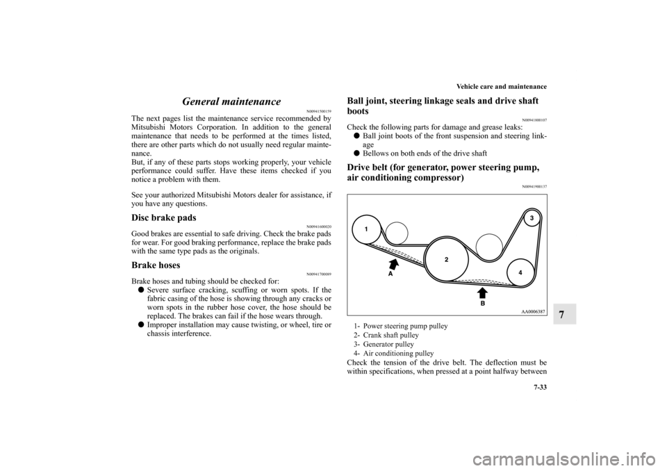
�Bellows on both ends of the drive shaftDrive belt (for generator, power steering pump,
air conditioning compressor)
N00941900137
Check the tension of the drive belt. The deflection must be
within specifications, when pressed at a point halfway between1- Power steering pump pulley
2- Crank shaft pulley
3- Generator pulley
4- Air conditioning pulley
BK0121600US.book 33 ページ 2010年4月12日 月曜日 午前10時39分
Page 466 of 514
Vehicle care and maintenance
7-39
7
Passenger compartment fuse location tablePassenger compartment fuse location
No.
Symbol
Electrical system
Capacity
1
Rear air conditioning 5 A
2— — —
3Radio 30 A
4 Sunroof 20 A
5 Rear window defogger 30 A
6 Heater 30 A
7— — —
8 — — —
9 Power outlet 15 A
10 Power door locks 15 A
11 Rear window wiper 15 A
12 — — —
13 Engine control 7.5 A
14 Outside rearview mirrors 7.5 A
15 — — —
16 Cigarette lighter 15 A
17 Engine control 7.5 A
18 — — —
19 Door mirror heater 7.5 A
20 Relay 7.5 A
BK0121600US.book 39 ページ 2010年4月12日 月曜日 午前10時39分
Page 468 of 514
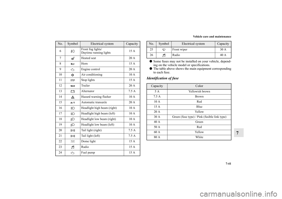
Vehicle care and maintenance
7-41
7
�Some fuses may not be installed on your vehicle, depend-
ing on the vehicle model or specifications.
�The table above shows the main equipment corresponding
to each fuse.Identification of fuse
6Front fog lights/
Daytime running lights15 A
7 Heated seat 20 A
8 Horn 15 A
9 Engine control 20 A
10 Air conditioning 10 A
11 Stop lights 15 A
12 Trailer 20 A
13 Alternator 7.5 A
14 Hazard warning flasher 10 A
15 Automatic transaxle 20 A
16 Headlight high beam (right) 10 A
17 Headlight high beam (left) 10 A
18 Headlight low beam (right) 10 A
19 Headlight low beam (left) 10 A
20 Tail light (right) 7.5 A
21 Tail light (left) 7.5 A
22 Dome light 15 A
23 Radio 15 A
24
Fuel pump 15 A No.
Symbol
Electrical system
Capacity
25 Front wiper 30 A
26 Radio 40 A Capacity
Color
5 A Yellowish brown
7.5 A Brown
10 A Red
15 A Blue
20 A Yellow
30 A Green (fuse type) / Pink (fusible link type)
40 A Green
50 A Red
60 A Yellow
80 A White
No.
Symbol
Electrical system
Capacity
BK0121600US.book 41 ページ 2010年4月12日 月曜日 午前10時39分