Page 153 of 196

Replacing componentsMOBILITY
151
License plate lamps
5watt bulb, C5W
1.Using a screwdriver, push the lamp to the
left in the tab of the lamp housing, arrow 1.
2. Remove the lamp, arrow 2 .
3. Replace the bulb.
4. Insert the lamp.
Center brake lamp
This lamp uses LED technology for operation. In
the event of a malfunction, contact your MINI
dealer or a workshop that has specially trained
personnel working in acco rdance with the spec-
ifications of your MINI manufacturer.
Repairing a flat tire
Safety measures in the event of a break-
down:
Park the vehicle as far as possible from moving
traffic and switch on th e hazard warning flash-
ers.
Turn the steering wheel until the front wheels
are in the straight-ahead position and engage
the steering wheel lock. Engage the parking
brake and shift into 1st or reverse gear or place
the selector lever in position P.
All passengers should be outside the vehicle and
in a safe place, e.g. behind a guardrail.
Erect a warning triangle or warning flasher at the
appropriate distance if necessary. Comply with
all safety guidelines and regulations.
should be followed depending on the equip-
ment included in your vehicle:
>
MINI Mobility System, refer to the following
section
> Run-flat tires, page 153
> Tire change with space-saver spare tire,
page 153
MINI Mobility System*
Preparations
Use of the MINI Mobility System may be ineffec-
tive if the tire puncture measures approx. 1/8 in/
4 mm or more. Contact the nearest MINI dealer
if the tire cannot be made drivable with the
Mobility System.
Do not remove foreign bodies which have pen-
etrated the tire if possible.
Follow the instructions on using the Mobil-
ity System found on the compressor and
the sealant bottle. <
Remove the adhesive label for the speed limit
from the sealant bottle and affix it to the steer-
ing wheel.
Sealant and compressor
1 Sealant bottle and adhesi ve label with speed
limit
2 Filling hose
Note the use-by date on the sealant bot-
tle. <
Page 154 of 196

MOBILITYReplacing components
152
3Holder for the sealant bottle
4 Compressor
5 Plug and cable for the socket in the vehicle
interior, page 87
6 Connection hose to connect the compressor
and sealant bottle or the compressor and
wheel
7 On/off switch
8 Pressure gauge for indi cating the tire infla-
tion pressure
9 Release button for reduci ng the tire inflation
pressure
Connector, cable and connection hose are
stored in the compressor housing.
Using the Mobility System
To repair a tire puncture with the Mobility Sys-
tem, proceed as follows:
> Filling the tire with sealant
> Distributing the sealant
> Correct the tire inflation pressure
Filling the tire with sealant
Proceed in the specified order; otherwise,
sealant may emerge under high pres-
sure. <
1. Shake the sealant bottle.
2. Pull the connecting hose 6 completely out of
the compressor housing and screw it onto
the connector of the sealant bottle. Make
sure that the hose is not kinked.
3. Insert the sealant bo ttle on the compressor
housing in an upright position. 4.
Unscrew the dust cap from the valve of the
defective wheel and screw the filling hose 2
of the sealant bottle onto the valve.
5. Ensure that the compre ssor is switched off.
6. Insert the plug 5 into the lighter socket/
power socket in the vehicle interior,
page 87.
7. With the engine running:
Switch on the compressor and let is run for
approx. 3 to 8 minutes to fill the tire with
sealant and achieve a ti re inflation pressure
of approx. 26 psi/180 kPa.
When filling the tire with sealant, the
inflation pressure can briefly rise to
approx. 73 psi/500 kPa. Do not switch off
the compressor during this phase. <
Do not run the compressor for longer
than 10 minutes; otherwise, the
device will overheat and possibly be dam-
aged.<
8. Switch off the compressor.
If an air pressure of 26 psi/180 kPa is not
reached:
1. Unscrew the filling hose 2 from the wheel
and drive the vehicle forward and backward
approx. 33 ft/10 m to distribute the liquid
sealant in the tire evenly.
2. Inflate the tire again with the compressor.
If an inflation pressure of 26 psi/180 kPa
still cannot be reached, the tire is too
heavily damaged. Please contact the nearest
MINI dealer. <
Page 155 of 196

Replacing componentsMOBILITY
153
Stowing Mobility System
1.Unscrew filler hose 2 of the sealant bottle
from the wheel.
2. Unscrew connecting hose of the
compressor 6 from the sealant bottle.
3. Connect the filler hose 2 of the sealant bot-
tle to the unoccupied connection on the
sealant bottle.
This prevents the rest of the sealant from
escaping from the bottle.
4. Wrap the empty sealant bottle in suitable
material to avoid dirtying the cargo area.
5. Stow Mobility System back in the vehicle.
Distributing the sealant
Immediate drive approx. 3.1 miles/5 km so that
the sealant evenly distributes itself.
Do not exceed speeds of 50 mph/
80 km/h.
If possible, do not drop below 10 mph/
20 km/h.<
Adjusting the tire pressure
1. After driving approx. 3.1 miles/5 km or
10 minutes, stop at a suitable location.
2. Screw the connection hose 6 of the com-
pressor directly onto the tire valve.
3. Insert the plug 5 into the power socket in
the vehicle interior.
4. Correct inflation pressu re to 26 psi/180 kPa.
With the engine running:
> To increase the inflatio n pressure: switch on
the compressor. To check the current infla-
tion pressure, switch off the compressor.
Do not run the compressor for longer
than 10 minutes; otherwise, the
device will overheat and possibly be dam-
aged. <
> To decrease the inflation pressure: press the
release button 9. If the tire cannot ma
intain the inflation
pressure, drive the vehicle again, refer to
Distributing the sealan t. Then repeat steps
1to4.
If an inflation pressure of 26 psi/180 kPa still
cannot be reached, the tire is too heavily dam-
aged. Contact the nearest MINI dealer. <
Driving on
Do not exceed the permitted maximum
speed of 50 mph/80 km/h; doing so may
result in an accident.<
Replace the defective tire as soon as possible
and have the new wheel/tire assembly bal-
anced.
Have the Mobility System refilled.
Changing wheels
Run-flat tires*
Tire change for run-flat tires:
> Prepare for tire change, page 154
> Jack up vehicle, page 154
> Tighten lug bolts, page 155
Space-saver spare tire*
Tire change with space-saver spare tire:
>Remove the space-saver spare tire,
page 154
> Prepare for tire change, page 154
> Jack up vehicle, page 154
> Mount space-saver spare tire, page 155
> Tighten lug bolts, page 155
> Drive with space-saver spare tire, page 154
Page 156 of 196

MOBILITYReplacing components
154
Removing the space-saver spare tire
The space-saver spare tire is located under the
tire change set in the cargo area.
1.Fold up the floor mat.
2. Unscrew the nut, arrow, and remove the
space-saver spare tire.
Driving with the space-saver spare tire
Drive cautiously and do not exceed a
speed of 50 mph/80 km/h. Changes may
occur in vehicle handling such as lower track sta-
bility during br aking, longer braking distances
and changes in self-steering properties when
close to the handling limit. These properties are
more noticeable with winter tires. <
Only one space-saver spare tire may be
mounted at one time. Mount a wheel and
tire of the original size as soon as possible, to
avoid any safety risks. <
Check the tire inflation pressure at the ear-
liest opportunity and correct it if neces-
sary. Replace the defective tire as soon as possi-
ble and have the new wheel/tire assembly
balanced. <
Preparing for a tire change
Observe the safety precautions regarding
flat tires on page 151.< Additional safety measures when chang-
ing tires:
Only change the tire wh en parked on a surface
that is level, firm and not slippery.
The vehicle or the jack could slip sideways on
soft or slippery support surfaces, such as snow,
ice, flagstones, etc.
Do not use a wooden block or similar object as a
support base for the jack, as this would prevent
it from extending to its full support height and
reduce its load-carrying capacity.
Do not lie under the vehicle or start the engine
when the vehicle is supported by the jack; other-
wise, there is a risk of fatal injury. <
1. Place the foldable chock
* behind the front
wheel on the other side of the vehicle or in
front of the wheel if the vehicle is on an
incline. If the wheel is changed on a surface
with a more severe sl ope, take additional
precautions to secure the vehicle from roll-
ing.
2. Uncover the lug bolts if necessary.
3. Loosen the lug bolts by a half turn.
Jacking up the vehicle
The vehicle jack is designed for changing
wheels only. Do not attempt to raise
another vehicle model with it or to raise any load
of any kind. To do so could cause accidents and
personal injury. <
Page 157 of 196

Replacing componentsMOBILITY
155
1.Place the jack at the jacking point closest to
the wheel.
The jack base must be perpendicular to the
surface beneath the jacking point.
2. During jacking up, insert the jack head in the
square recess of the jacking point.
3. Jack the vehicle up until the wheel you are
changing is raised off the ground.
Mounting the space-saver spare tire
1.Unscrew the lug bolts and remove the
wheel.
2. Remove accumulations of mud or dirt from
the mounting surfaces of the wheel and
hub. Clean the lug bolts.
3. Lift the new wheel into place.
4. Screw at least two lug bolts finger-tight into
opposite bolt holes.
5. Screw in the remaining bolts.
6. Tighten all the lug bolts firmly in a diagonal
pattern.
7. Lower the vehicle.
8. Remove the jack.
Tightening the lug bolts
Tighten the lug bolts in a diagonal pattern.
Immediately have the wheels checked
with a calibrated torque wrench to ensure
that the lug bolts are firmly seated. Otherwise,
incorrectly tightened lug bolts can present a
safety hazard. <
Tightening torque: 103.3 lb ft or 140 Nm. Replace the defective tire
as soon as possible
and have the new wheel/tire assembly bal-
anced.
Vehicle battery
Maintenance
The battery is 100 % maintenance-free, the
electrolyte will last for the life of the battery
when the vehicle is operated in a temperate cli-
mate.
Battery replacement
Only use vehicle batteries that have been
approved for your vehicle by the manu-
facturer; otherwise, the vehicle could be dam-
aged and systems or func tions may not be fully
available. <
After a battery replacement, have the battery
registered on the vehicle by your dealer to
ensure that all comfort functions are fully avail-
able.
Charging the battery
Only charge the battery in the vehicle when the
engine is off. Connection s, refer to Jump-start-
ing on page 157.
Disposal
After replacing old batteries, return the
used batteries to your MINI dealer or to a
recycling center. Maintain the battery in an
upright position for transport and storage.
Always secure the battery against tipping over
during transport. <
Power failure
After a temporary power loss, some equipment
may not be fully functional and may require ini-
tialization. Individual se ttings are also lost and
must be reprogrammed:
Page 158 of 196
MOBILITYReplacing components
156
>Time and date
These values must be updated, page 57.
> Radio
In some cases, statio ns may have to be
stored again, page 102.
> Glass roof
*, electric
It may only be possible to raise the roof, if
applicable. The system must be initialized.
Contact your near est MINI dealer.
Fuses
Do not attempt to repair a blown fuse or
replace it with a fuse of a different color or
Ampere rating. To do this could cause a fire in
the vehicle resulting from a circuit overload.
Have the fuse changed only by a MINI dealer or
a workshop that has specially trained personnel
working in accordance with the specifications of
the MINI manufacturer. <
A fuse allocation diagram is located on the inside
of the fuse box cover panels.
In the engine compartment
Opening the cover
Press the latch.
In the vehicle interior
On the right side of the footwell.
Opening the cover
Press out at the recess.
Page 159 of 196

Giving and receiving assistanceMOBILITY
157
Giving and receiving assistance
Roadside Assistance
Roadside Assistance is available by phone
24 hours a day in many countries. You can
receive assistance there in the event of an emer-
gency.
First aid pouch*
Some of the articles co ntained in the first aid
pouch have a limited se rvice life. Therefore,
check the expiration dates of the contents regu-
larly and replace any items in good time, if nec-
essary.
The first aid pouch is located on the rear cargo
well by the left side trim panel or under the flat
load floor.
Warning triangle*
In the cargo area under the loading sill. Open the center lock to take it out.
Jump-starting
If the car's own battery is flat, your MINI's engine
can be started by connecting two jumper cables
to another vehicle's battery. You can also use
the same method to help start another vehicle.
Only use jumper cables with fully-insulated
clamp handles.
Do not touch any electrically live parts
w hen the e ngin e is run ning, or a fatal acci-
dent may occur. Carefully adhere to the follow-
ing sequence, both to prevent damage to one or
both vehicles, and to guard against possible per-
sonal injuries. <
Preparation
1.Check whether the battery of the other vehi-
cle has a voltage of 12 volts and approxi-
mately the same capacitance in Ah. This
information can be found on the battery.
2. Switch off the engine of the support vehicle.
3. Switch off any consumers in both vehicles.
There must not be any contact between
the bodies of the two vehicles; otherwise,
there is a danger of shorting. <
Connecting jumper cables
Connect the jumper cables in the correct
o r d e r , s o t h a t n o s parks which could cause
injury occur. <
Page 160 of 196

MOBILITYGiving and receiving assistance
158
1.Open the battery cover in the engine com-
partment to access the positive terminal of
your MINI.
2. Release the tabs on the left and right sides of
the positive terminal cover
*, arrows 1, and
lift the cover to open, arrow 2.
3. Attach one terminal clamp of the plus/+
jumper cable to the positive terminal of the
battery or to a starting-aid terminal of the
vehicle providing assistance.
4. Attach the second terminal clamp of the
plus/+ jumper cable to the positive terminal
of the battery or a starting-aid terminal of
the vehicle to be started.
5. Attach one terminal clamp of the minus/–
jumper cable to the negative terminal of the
battery or to an engine or body ground of
the assisting vehicle. Body ground in MINI:
6.
Attach the second te rminal clamp of the
minus/– jumper cable to the negative termi-
nal of the battery or to the engine or body
ground of the vehicle to be started.
Starting the engine
1. Start the engine of the donor vehicle and
allow it to run for a few minutes at slightly
increased idle speed.
2. Start the engine of the other vehicle in the
usual manner.
If the first start attempt is not successful,
wait a few minutes before another attempt
in order to allow the discharged battery to
recharge.
3. Let the engines run for a few minutes.
4. Disconnect the jumper cables by reversing
the above connecting sequence.
If necessary, have the battery checked and
recharged. Never use spray fluids to start the
engine. <
Tow-starting, towing
away
Observe the applicable laws and regula-
tions for tow-starting and towing vehi-
cles. <
Do not transport any passengers other
than the driver in a vehicle that is being
towed. <
 1
1 2
2 3
3 4
4 5
5 6
6 7
7 8
8 9
9 10
10 11
11 12
12 13
13 14
14 15
15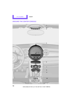 16
16 17
17 18
18 19
19 20
20 21
21 22
22 23
23 24
24 25
25 26
26 27
27 28
28 29
29 30
30 31
31 32
32 33
33 34
34 35
35 36
36 37
37 38
38 39
39 40
40 41
41 42
42 43
43 44
44 45
45 46
46 47
47 48
48 49
49 50
50 51
51 52
52 53
53 54
54 55
55 56
56 57
57 58
58 59
59 60
60 61
61 62
62 63
63 64
64 65
65 66
66 67
67 68
68 69
69 70
70 71
71 72
72 73
73 74
74 75
75 76
76 77
77 78
78 79
79 80
80 81
81 82
82 83
83 84
84 85
85 86
86 87
87 88
88 89
89 90
90 91
91 92
92 93
93 94
94 95
95 96
96 97
97 98
98 99
99 100
100 101
101 102
102 103
103 104
104 105
105 106
106 107
107 108
108 109
109 110
110 111
111 112
112 113
113 114
114 115
115 116
116 117
117 118
118 119
119 120
120 121
121 122
122 123
123 124
124 125
125 126
126 127
127 128
128 129
129 130
130 131
131 132
132 133
133 134
134 135
135 136
136 137
137 138
138 139
139 140
140 141
141 142
142 143
143 144
144 145
145 146
146 147
147 148
148 149
149 150
150 151
151 152
152 153
153 154
154 155
155 156
156 157
157 158
158 159
159 160
160 161
161 162
162 163
163 164
164 165
165 166
166 167
167 168
168 169
169 170
170 171
171 172
172 173
173 174
174 175
175 176
176 177
177 178
178 179
179 180
180 181
181 182
182 183
183 184
184 185
185 186
186 187
187 188
188 189
189 190
190 191
191 192
192 193
193 194
194 195
195