2011 MERCEDES-BENZ SLK55AMG light
[x] Cancel search: lightPage 178 of 312
Useful features
Cup holder
G
Warning!
In order to help prevent spilling liquids on
vehicle occupants and/or vehicle equipment,
only use containers that fit into the cup
holder. Use lids on open containers and do
not fill containers to a height where the
contents, especially hot liquids, could spill
during braking, vehicle maneuvers, or in an
accident. Liquids spilled on vehicle occupants
may cause serious personal injury. Liquids
spilled on vehicle equipment may cause
damage not covered by the Mercedes-Benz
Limited Warranty.
When not in use, keep the cup holder closed.
An open cup holder may cause injury to you
or others when contacted during braking,
vehicle maneuvers, or in an accident.
Keep in mind that objects placed in the cup
holder may come loose during braking,
vehicle maneuvers, or in an accident and be
thrown around in the vehicle interior. Objects
thrown around in the vehicle interior may
cause an accident and/or serious personal
injury. X
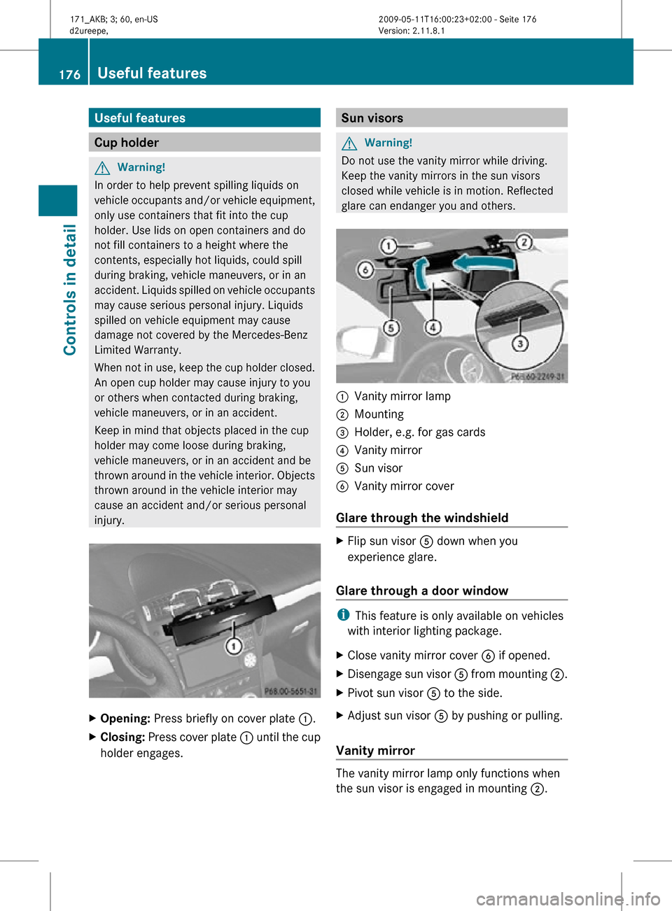
Opening: Press briefly on cover plate :.
X Closing: Press cover plate : until the cup
holder engages. Sun visors
G
Warning!
Do not use the vanity mirror while driving.
Keep the vanity mirrors in the sun visors
closed while vehicle is in motion. Reflected
glare can endanger you and others. :
Vanity mirror lamp
; Mounting
= Holder, e.g. for gas cards
? Vanity mirror
A Sun visor
B Vanity mirror cover
Glare through the windshield X
Flip sun visor A down when you
experience glare.
Glare through a door window i
This feature is only available on vehicles
with interior lighting package.
X Close vanity mirror cover B if opened.
X Disengage sun visor A from mounting ;.
X Pivot sun visor A to the side.
X Adjust sun visor A by pushing or pulling.
Vanity mirror The vanity mirror lamp only functions when
the sun visor is engaged in mounting ;.176
Useful featuresControls in detail
171_AKB; 3; 60, en-US
d2ureepe,
Version: 2.11.8.1 2009-05-11T16:00:23+02:00 - Seite 176
Page 179 of 312
X
Lift up vanity mirror cover B.
Vanity mirror lamp : comes on. Ashtray
X
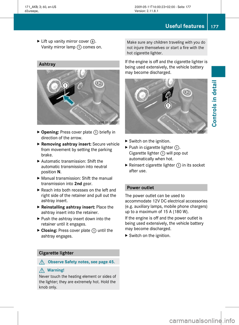
Opening: Press cover plate : briefly in
direction of the arrow.
X Removing ashtray insert: Secure vehicle
from movement by setting the parking
brake.
X Automatic transmission: Shift the
automatic transmission into neutral
position N.
X Manual transmission: Shift the manual
transmission into 2nd gear.
X Reach into both recesses on the left and
right side of the retainer and pull out the
ashtray insert.
X Reinstalling ashtray insert: Place the
ashtray insert into the retainer.
X Push the ashtray insert down into the
retainer until it engages.
X Closing: Press cover plate : until the
ashtray engages. Cigarette lighter
G
Observe Safety notes, see page 45. G
Warning!
Never touch the heating element or sides of
the lighter; they are extremely hot. Hold the
knob only. Make sure any children traveling with you do
not injure themselves or start a fire with the
hot cigarette lighter.
If the engine is off and the cigarette lighter is
being used extensively, the vehicle battery
may become discharged. X
Switch on the ignition.
X Push in cigarette lighter :.
Cigarette lighter : will pop out
automatically when hot.
X Reinsert cigarette lighter : in its socket
after use. Power outlet
The power outlet can be used to
accommodate 12V DC electrical accessories
(e.g. auxiliary lamps, mobile phone chargers)
up to a maximum of 15 A (180 W).
If the engine is off and the power outlet is
being used extensively, the vehicle battery
may become discharged.
X Switch on the ignition. Useful features
177Controls in detail
171_AKB; 3; 60, en-US
d2ureepe, Version: 2.11.8.1 2009-05-11T16:00:23+02:00 - Seite 177 Z
Page 186 of 312
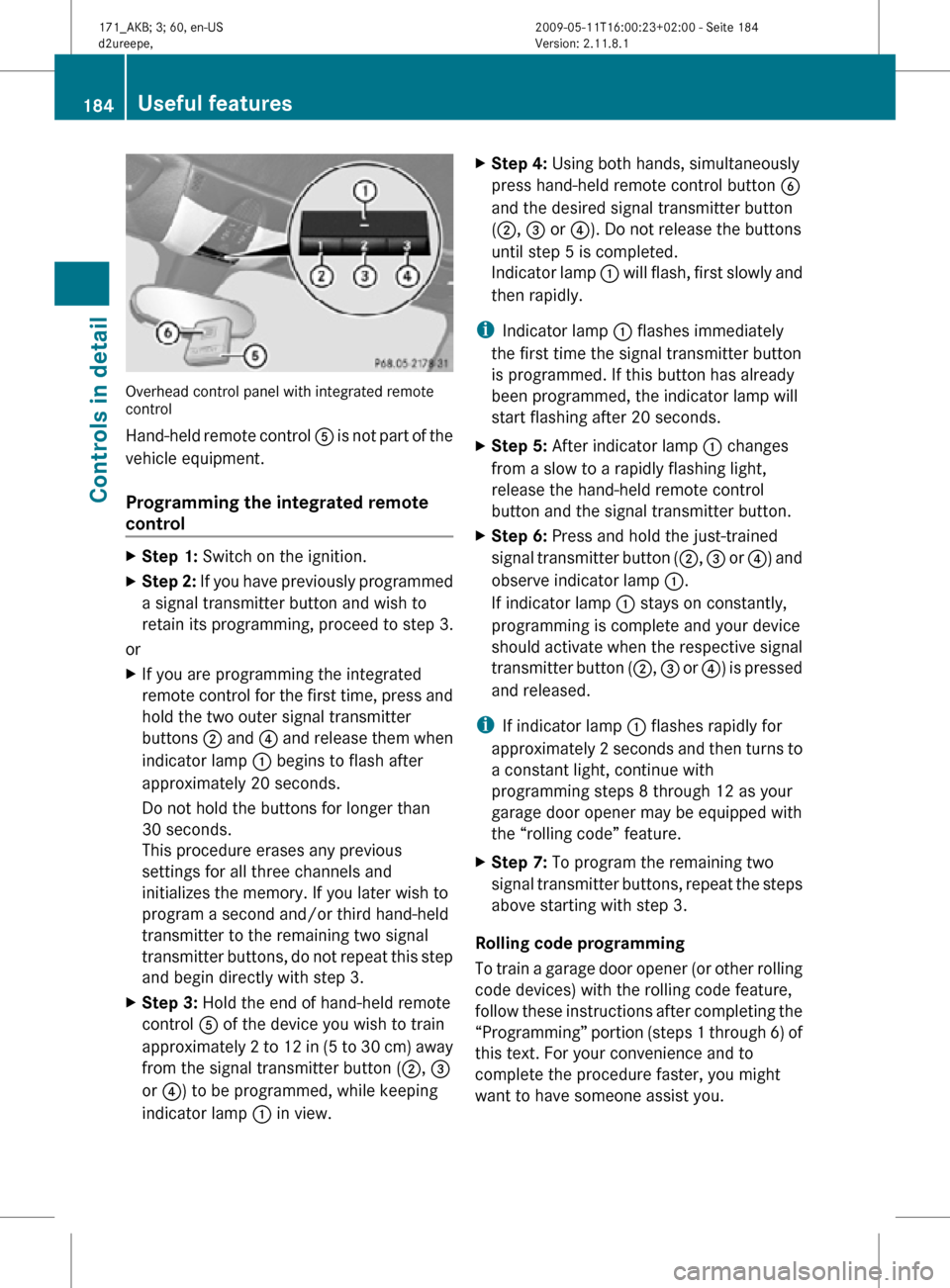
Overhead control panel with integrated remote
control
Hand-held remote control
A is not part of the
vehicle equipment.
Programming the integrated remote
control X
Step 1: Switch on the ignition.
X Step 2: If you have previously programmed
a signal transmitter button and wish to
retain its programming, proceed to step 3.
or
X If you are programming the integrated
remote control for the first time, press and
hold the two outer signal transmitter
buttons ; and ? and release them when
indicator lamp : begins to flash after
approximately 20 seconds.
Do not hold the buttons for longer than
30 seconds.
This procedure erases any previous
settings for all three channels and
initializes the memory. If you later wish to
program a second and/or third hand-held
transmitter to the remaining two signal
transmitter buttons, do not repeat this step
and begin directly with step 3.
X Step 3: Hold the end of hand-held remote
control A of the device you wish to train
approximately 2 to 12 in (5 to 30 cm) away
from the signal transmitter button ( ;, =
or ?) to be programmed, while keeping
indicator lamp : in view. X
Step 4: Using both hands, simultaneously
press hand-held remote control button B
and the desired signal transmitter button
(;, = or ?). Do not release the buttons
until step 5 is completed.
Indicator lamp : will flash, first slowly and
then rapidly.
i Indicator lamp : flashes immediately
the first time the signal transmitter button
is programmed. If this button has already
been programmed, the indicator lamp will
start flashing after 20 seconds.
X Step 5: After indicator lamp : changes
from a slow to a rapidly flashing light,
release the hand-held remote control
button and the signal transmitter button.
X Step 6: Press and hold the just-trained
signal transmitter button (;, = or ?) and
observe indicator lamp :.
If indicator lamp : stays on constantly,
programming is complete and your device
should activate when the respective signal
transmitter button ( ;, = or ?) is pressed
and released.
i If indicator lamp : flashes rapidly for
approximately 2 seconds and then turns to
a constant light, continue with
programming steps 8 through 12 as your
garage door opener may be equipped with
the “rolling code” feature.
X Step 7: To program the remaining two
signal transmitter buttons, repeat the steps
above starting with step 3.
Rolling code programming
To train a garage door opener (or other rolling
code devices) with the rolling code feature,
follow these instructions after completing the
“Programming” portion (steps 1 through 6) of
this text. For your convenience and to
complete the procedure faster, you might
want to have someone assist you. 184
Useful featuresControls in detail
171_AKB; 3; 60, en-US
d2ureepe,
Version: 2.11.8.1 2009-05-11T16:00:23+02:00 - Seite 184
Page 187 of 312
X
Step 8: Locate the “training” button on the
garage door opener motor head unit.
i Exact
location and color of the button may
vary by garage door opener brand.
Depending on manufacturer, the “training”
button may also be referred to as “learn” or
“smart” button. If there is difficulty locating
the transmitting button, refer to the garage
door opener Operator’s Manual.
X Step 9: Press the “training” button on the
garage door opener motor head unit.
The “training light” is activated.
You have 30 seconds to initiate the
following two steps.
X Step 10: Return to the vehicle and firmly
press, hold for 2 seconds and release the
programmed
signal transmitter button (;,
= or ?).
X Step 11: Press, hold for 2 seconds and
release same signal transmitter button a
second time to complete the training
process.
i Some garage door openers (or other
rolling
code equipped devices) may require
you to press, hold for 2 seconds and
release the same signal transmitter button
a third time to complete the training
process.
X Step 12: Confirm the garage door
operation by pressing the programmed
signal transmitter button ( ;, = or ?).
X Step 13: To program the remaining two
signal
transmitter buttons, repeat the steps
above starting with step 3.
Gate operator/Canadian programming
Canadian radio-frequency laws require
transmitter signals to “time-out” (or quit)
after several seconds of transmission which
may not be long enough for the integrated
signal
transmitter to pick up the signal during
programming. Similar to this Canadian law,
some U.S. gate operators are designed to
“time-out” in the same manner. If you live in Canada or if you are having
difficulties programming a gate operator
(regardless of where you live) by using the
programming
procedures, replace step 4 with
the following:
X Step 4: Press and hold the signal
transmitter button ( ;, = or ?). Do not
release this button until it has been
successfully trained.
X While still holding down the signal
transmitter button ( ;, = or ?), “cycle”
your hand-held remote control button B
as follows: Press and hold button B for
2 seconds, then release it for 2 seconds,
and again press and hold it for 2 seconds.
Repeat this sequence on the hand-held
remote control until the frequency signal
has been learned.
Upon successful training, indicator
lamp : will flash slowly and then rapidly
after several seconds.
X Proceed with programming step 5 and
step 6 to complete.
i Upon completion of programming the
integrated remote control, make sure you
retain the hand-held remote control that
came with the garage door opener, gate
operator or other device. You may need it
for use in other vehicles, for future
programming of an integrated remote
control, or simply for continued use as a
hand-held remote control to operate the
respective device in other situations.
Reprogramming a single signal
transmitter button To program a device using a signal
transmitter button previously trained, follow
these steps: Useful features
185
Controls in detail
171_AKB; 3; 60, en-US
d2ureepe, Version: 2.11.8.1 2009-05-11T16:00:23+02:00 - Seite 185 Z
Page 194 of 312

Check the following:
R
Engine oil level ( Y page 193)
R Tire inflation pressure ( Y page 201)
R Coolant level ( Y page 196)
R Vehicle lighting ( Y page 267)
R Washer system and headlamp cleaning
system (Y page 196)
R Brake fluid ( Y page 197) Engine compartment
Hood
G
Warning!
Do not pull the release lever while the vehicle
is in motion. Otherwise the hood could be
forced open by passing air flow.
This could cause the hood to come loose and
injure you and/or others.
Opening G
Warning!
Do not open the hood when the engine is
overheated. You could be seriously injured.
Observe the coolant temperature display to
determine whether the engine may be
overheated. If you see flames or smoke
coming from the engine compartment, move
away from the vehicle. Wait until the engine
has cooled. If necessary, call the fire
department. G
Warning!
You could be injured when the hood is open –
even when the engine is turned off.
Parts of the engine can become very hot. To
prevent burns, let the engine cool completely
before touching any components on the
vehicle. Comply with all relevant safety
precautions. G
Warning!
To help prevent personal injury, stay clear of
moving parts when the hood is open and the
engine is running.
The radiator fan may continue to run for
approximately 30 seconds or may even
restart after the engine has been turned off.
Stay clear of fan blades. G
Warning!
The engine is equipped with a transistorized
ignition system. Because of the high voltage
it is dangerous to touch any components
(ignition coils, spark plug sockets, diagnostic
socket) of the ignition system
R with the engine running
R while starting the engine
R when the ignition is switched on and the
engine is turned manually X
Pull hood lock release lever :.
The hood is unlocked.
! Never open the hood if the wiper arms are
folded forward away from the windshield.
Otherwise the windshield wipers or the
hood could be damaged. 192
Engine compartmentOperation
171_AKB; 3; 60, en-US
d2ureepe,
Version: 2.11.8.1 2009-05-11T16:00:23+02:00 - Seite 192
Page 212 of 312
Life of tire
G
Warning!
Tires and spare tire should be replaced after
6 years, regardless of the remaining tread.
The service life of a tire is dependent upon
varying factors including but not limited to:
R Driving style
R Tire inflation pressure
R Distance driven
Tread depth G
Warning!
Although the applicable federal motor vehicle
safety laws consider a tire to be worn when
the treadwear indicators (TWI) become visible
at approximately 1
/ 16 in (1.6 mm), we
recommend that you do not allow your tires
to wear down to that level. As tread depth
approaches 1
/ 8 in (3 mm), the adhesion
properties on a wet road are sharply reduced.
Depending upon the weather and/or road
surface (conditions), the tire traction varies
widely.
Do not allow your tires to wear down too far.
Adhesion properties on wet roads are sharply
reduced at tread depths of less than 1
/ 8 in
(3 mm).
Treadwear indicators (TWI) are required by
law. These indicators are located in six places
on the tread circumference and become
visible at a tread depth of approximately
1 / 16 in (1.6 mm), at which point the tire is
considered worn and should be replaced.
The recommended minimum tire tread depth
for summer tires is 1
/ 8 in (3 mm). The
recommended minimum tire tread depth for
winter tires is 1
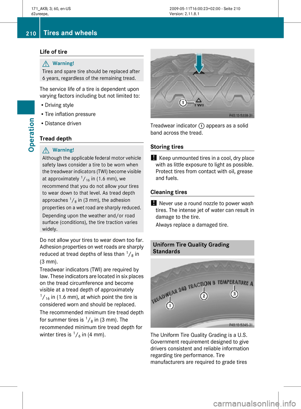
/ 6 in (4 mm). Treadwear indicator
: appears as a solid
band across the tread.
Storing tires !
Keep unmounted tires in a cool, dry place
with as little exposure to light as possible.
Protect tires from contact with oil, grease
and fuels.
Cleaning tires !
Never use a round nozzle to power wash
tires. The intense jet of water can result in
damage to the tire.
Always replace a damaged tire. Uniform Tire Quality Grading
Standards
The Uniform Tire Quality Grading is a U.S.
Government requirement designed to give
drivers consistent and reliable information
regarding tire performance. Tire
manufacturers are required to grade tires210
Tires and wheelsOperation
171_AKB; 3; 60, en-US
d2ureepe,
Version: 2.11.8.1 2009-05-11T16:00:23+02:00 - Seite 210
Page 215 of 312
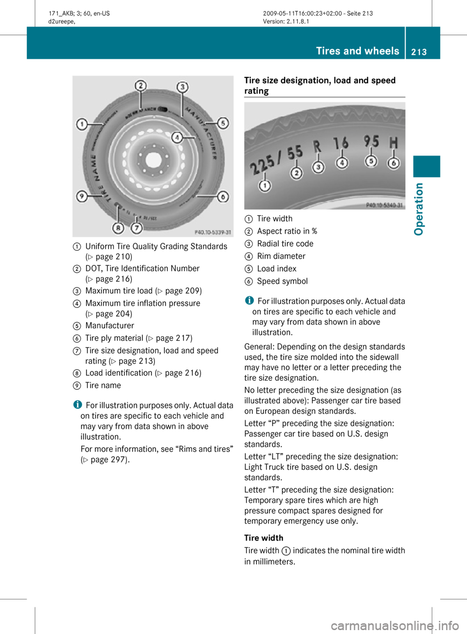
:
Uniform Tire Quality Grading Standards
(Y page 210)
; DOT, Tire Identification Number
(Y page 216)
= Maximum tire load ( Y page 209)
? Maximum tire inflation pressure
(Y page 204)
A Manufacturer
B Tire ply material ( Y page 217)
C Tire size designation, load and speed
rating (Y page 213)
D Load identification ( Y page 216)
E Tire name
i For illustration purposes only. Actual data
on tires are specific to each vehicle and
may vary from data shown in above
illustration.
For more information, see “Rims and tires”
(Y page 297). Tire size designation, load and speed
rating :
Tire width
; Aspect ratio in %
= Radial tire code
? Rim diameter
A Load index
B Speed symbol
i For illustration purposes only. Actual data
on tires are specific to each vehicle and
may vary from data shown in above
illustration.
General: Depending on the design standards
used, the tire size molded into the sidewall
may have no letter or a letter preceding the
tire size designation.
No letter preceding the size designation (as
illustrated above): Passenger car tire based
on European design standards.
Letter “P” preceding the size designation:
Passenger car tire based on U.S. design
standards.
Letter “LT” preceding the size designation:
Light Truck tire based on U.S. design
standards.
Letter “T” preceding the size designation:
Temporary spare tires which are high
pressure compact spares designed for
temporary emergency use only.
Tire width
Tire width : indicates the nominal tire width
in millimeters. Tires and wheels
213Operation
171_AKB; 3; 60, en-US
d2ureepe, Version: 2.11.8.1 2009-05-11T16:00:23+02:00 - Seite 213 Z
Page 218 of 312
any authorized Mercedes-Benz Center will be
glad to assist you.
Load identification
i
For illustration purposes only. Actual data
on tires are specific to each vehicle and
may vary from data shown in above
illustration.
In addition to the load index, special load
identification : may be molded into the tire
sidewall following the letter designating the
speed symbol B (Y page 213).
R No specification given: absence of any text
(like in above example) indicates a
standard load (SL) tire.
R XL or Extra Load: designates an extra load
(or reinforced) tire.
R Light Load: designates a light load tire.
R C, D, E: designates load range associated
with the maximum load a tire can carry at
a specified pressure. DOT, Tire Identification Number (TIN)
U.S. tire regulations require each new tire
manufacturer or tire retreader to mold a TIN
into or onto a sidewall of each tire produced. The TIN is a unique identifier. The TIN
facilitates efforts by tire manufactures to
notify purchasers in recall situations or other
safety matters concerning tires. It gives
purchasers the means to easily identify such
tires.
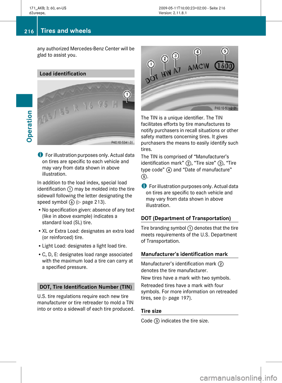
The TIN is comprised of “Manufacturer’s
identification mark” ;, “Tire size”
=, “Tire
type code” ? and “Date of manufacture”
A.
i For illustration purposes only. Actual data
on tires are specific to each vehicle and
may vary from data shown in above
illustration.
DOT (Department of Transportation) Tire branding symbol
: denotes that the tire
meets requirements of the U.S. Department
of Transportation.
Manufacturer’s identification mark Manufacturer’s identification mark ;
denotes the tire manufacturer.
New tires have a mark with two symbols.
Retreaded tires have a mark with four
symbols. For more information on retreaded
tires, see (
Y page 197).
Tire size Code
= indicates the tire size. 216
Tires and wheelsOperation
171_AKB; 3; 60, en-US
d2ureepe,
Version: 2.11.8.1 2009-05-11T16:00:23+02:00 - Seite 216