2011 MERCEDES-BENZ M-CLASS SUV ECU
[x] Cancel search: ECUPage 319 of 389

Frequencies for th
egarage doo ropener Th
er adio typ eapproval number and th efrequency range for th egarag edoor opener can be
fou ndonthe Interne tat: http://www.mercedes-benz.de/betriebsanleitung. Floormats
G
WARNING
Make sure that there is sufficient clearance
around the pedals when floormats are used,
and that the floormats are properly secured.
The floormats must be correctly secured at all
times using retainer sand press-studs.
Before you drive off ,chec kthe floormats and
secur eifnecessary. Afloormat which is not
properly secured can slip and, thereby, inter-
fere with the movemen tofthe pedals.
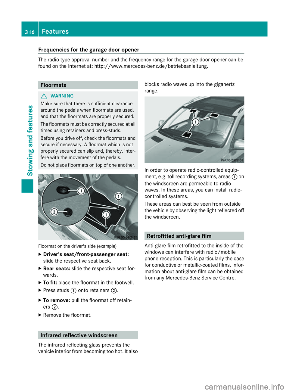
Do not plac efloormats on top of one another. Floormat on the driver's side (example)
X
Driver's seat/front-passenger seat:
slide the respective seat back.
X Rear seats: slide the respective seat for-
wards.
X To fit: place the floorma tinthe footwell.
X Press studs :ontoretainers ;.
X To remove: pull the floormat off retain-
ers ;.
X Remov ethe floormat. Infrared reflective windscreen
The infrared reflecting glass prevents the
vehicle interior from becoming too hot. It also blocks radio waves up int
othe gigahertz
range. In orde
rtooperateradio-controlled equip-
ment, e.g. toll recording systems, areas :on
the windscreen are permeable to radio
waves. In these areas, you can install radio-
controlled systems.
Thes earea scan best be seen from outside
the vehicle by observing the light reflected off
the windscreen. Retrofitted anti-glar
efilm
Anti-glar efilm retrofitted to the inside of the
windows can interfer ewith radio/mobile
phone reception. This is particularly the case
for conductive or metallic-coated films. Infor-
mation about anti-glar efilm can be obtained
from any Mercedes-Ben zService Centre. 316
FeaturesStowing and features
Page 324 of 389

Examp
le:e ngine oi lcap
X Turn cap :anti-clockwise and remove it.
X Top up the engine oil.
If the oi llev el is at or belo wthe MIN mark
on the dipstick ,top up with
0. 5to1 .0 litres of engine oil.
X Replace cap :on the fille rneck and turn
clockwise.
Make sure that the cap locks into place
securely.
X Check the oil level agai nwith the oil dip-
stick (Y page 320).
Further information on engine oil
(Y page 375). Checking and adding other service
products
Checking the coolant level Only check the coolant level when the vehicle
is on alevel surface and the engine has cooled
down.
X Turn the key to position 2(Y page 139) in
the ignition lock.
On vehicles with KEYLESS-GO, press the
Start/Stop button twic e(Ypage 139).
X Check the coolant temperatur egauge in
the multifunction displ ay.G
WARNING
Th ec ooling system is pressurised. Therefore,
only unscrew the cap once the engin ehas
cooled down. The coolant temperature gauge must display less than 70
†.Otherwi se,you
could be scalded if ho tcoolant escapes. X
Slowl yturn cap :half aturna nti-clock-
wis eand allo wexcess pressure to escape.
X Turn cap :further anti-clockwis eand
remove it.
If the coolant is at the level of markerbar
= in the filler nec kwhen cold ,ther eis
enough coolan tincoolant expansion
tank ;.
If the coolant leve lisapproximately 1.5 cm
above marker bar =in the filler nec kwhen
warm, ther eisenoughcoolant in coolant
expansion tank ;.
X If necessary ,top up with coolant that has
been tested and approved by Mercedes-
Ben z.
X Replace cap :and turn it clockwise as far
as it will go.
For further information on coolant, see
(Y page 377).
Windscreen washer system and head-
lamp cleanin gsystem Th
ew asher fluid reservoir is used for both the
windscreen washe rsystem and the headlamp
cleaning system.
i Components and service products must
be matched. Mercedes-Benz recommends
that you use products teste dand approved
by Mercedes-Be nz.T hey ar elisted in this
Mercedes-Ben zOwner's Manual in the
appropriat esection. Engine compartment
321Maintenance andcare Z
Page 330 of 389

Do not touch the insides of the windows
with hard objects
,e.g.ani ce scraper or
ring .There is otherwise arisk of damaging
the windows.
! Clean the water drainage channels of the
windscreen and the rear window at regular
intervals. Deposits such as leaves, petals
and pollen may under certain circumstan-
ces prevent water from drainin gaway .This
can lead to corrosion damage and damage
to electronic components.
Cleaning th ewiper blades G
WARNING
Switch off the windscreen wipers and remove
the key from the ignition lock befor ecleaning
the windscreen or the wiper blades. On vehi-
cles with KEYLESS-GO, press the Star t/Stop
butto nrepeatedly unti lall indicator lamps in
the instrumen tcluster have gone off. The
windscreen wipers could otherwise move and
injur eyou.
! Do not pull on the wiper blade. Otherwise,
the wiper blade could be damaged.
! Do not clean wiper blades too often and
do not rub them too hard. Otherwise, the
graphit ecoatin gcould be damaged. This
coul dcause wiper noise.
X Fold the wiper arms away from the wind-
screen.
X Clea nthe wiper blades carefully usin ga
damp cloth.
X Fold the windscreen wipers back again
befor eswitching on the ignition.
! Hold the wiper arm securely when folding
back. The windscreen could be damaged if
the wiper arm hits against it suddenly.
Cleanin gthe exterio rlighting X
Clean the plastic lenses of the exterior
lighting using awet sponge and amild
cleaning agent, e.g. Mercedes-Ben zcar
shampoo or cleanin gcloths. !
Only use cleanin gagents or cleaning
cloth sthat ar esuitable for plastic lenses.
Unsuitable cleanin gagents or cleaning
cloth scoul dscratch or damag ethe plastic
lenses of th eexteri or lighting.
Clea ningthe sensors X
Clean sensors :of th edriving systems
with water, car shampoo and asoftc loth.
! If you clean the sensor swithahigh-pres-
sure cleaner, mak esure that you keep a
distanc eofatl east 30 cm between the
vehicle and the high-pressure cleaner noz-
zle. Information about the correc tdistance
is available from the equipment manufac-
turer.
Cleaning th ereversing camera Care
327Maintenance andcare Z
Page 341 of 389

genc
yspare wheel/spar ewheel the handling
characteristic softhe vehicle ma ychange.
Adap tyour style of driving accordingly.
Never operate the vehicle with mor ethan one
emergenc yspare wheel/spar ewheel that dif-
fer sins ize.
Only use an emergenc yspare wheel/spare
wheel of adiffering size briefly and do not
switch off ESP ®
.
When using an emergenc yspare wheel you
must not exceed the maximum speed of
80 km/h. G
WARNING
Hav ethe emergenc yspare wheel/spare
wheel replaced with anew wheel as soon as
possible at aqualified specialist workshop
which has the necessary specialist knowledge
and tools to carry out the work required.
Mercedes-Benz recommends that you use a
Mercedes-Benz Service Centre for this pur-
pose .Inp articular, work relevant to safety or
on safety-related systems must be carried out
at aq ualified specialist workshop.
i Vehicles withou tanemergency spare
wheel/spare whee lare not equippe dwith
wheel-changing tools at the factory. For
more information on which tools are
required to perfor mawheel change on your
vehicle, e.g. wheel chock ,wheel wrenc hor
centring pin, consult aMercedes-Benz
Servic eCentre.
X Prepar ethe vehicle as described
(Y page 334).
X Ifat railer is coupled to th evehicle, uncou-
ple it.
X Remov ethe followin gitems (depending on
the vehicle's equipment) from the stowage
well under the luggage compartment floor:
R the emergency spare wheel 23
R the whee lwrench
R thef olding wheel chock
R the jack R
the ratchet rin gspanner
R the centrin gpin
X Secur ethe vehicle to preven titfrom rolling
awa y.
Se curing the vehicle to prevent it from
rolling away If your vehicle is equippe
dwithaw heel choc k,
it can be found in the vehicle tool kit
(Y page 333).
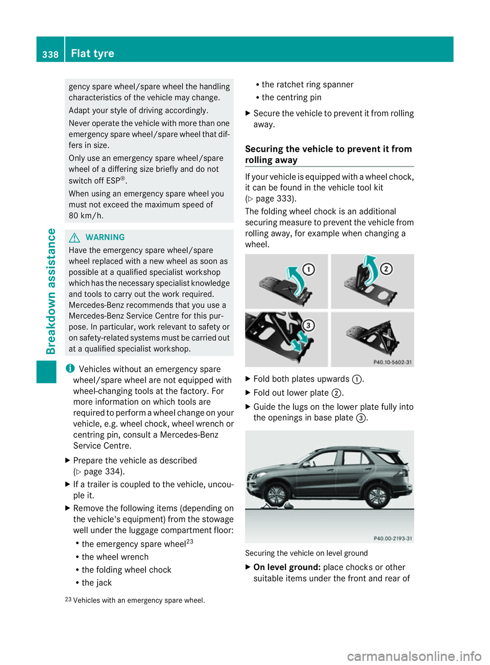
The folding wheel chock is an additional
securing measure to prevent the vehicle from
rolling away, for example when changing a
wheel. X
Fold both plates upwards :.
X Fold out lower plate ;.
X Guide the lugs on the lower plate fully into
the openings in base plate =. Securing the vehicle on level ground
X
On level ground: place chocksorother
suitable items under the front and rear of
23 Vehicles with an emergenc yspare wheel. 338
Flat tyreBreakdown assistance
Page 342 of 389

the whee
lthat is diagona llyo pposite the
wheel you wish to change. Securing the vehicle on slight downhil
lgradients
X On downhill gradients: place chocks or
othe rsuitabl eitems in front of the wheels
of the front and rear axle.
Raisin gthe vehicle G
WARNING
Th ejack is intended only for lifting the vehicle
briefly for wheel changes.
The vehicle must be placed on stands if you
intend to work under it.
Make sure that the jack is placed on afirm,
non-slip, level surface. Do not use wooden
blocks or similar objects as ajack underlay.
The vehicle could otherwise slip off the jack
and seriousl yinjure you.
Do not start the engine at any time whil ethe
wheel is being changed.
Do not lie unde rthe vehicle when it is being
supported by the jack. If you do not raise the
vehicle as described, it coul dslip off the jack
(e.g. if the engine is started or adoor or the
tailgate is opened or closed) and seriously
injure you. G
WARNING
If you fai ltoposition the jac kcorrectly, the
vehicle may:
R slip off the jack
R injure you or others
R be damaged. Therefore, mak
esure that the jack is posi-
tioned correctly in the respective jacking
points. Before positioning the jack, remove
any dirt that may have collected in the jacking
points. Pleas enote that you must position the
jac kint he openin gofthe jackin gpoint. X
Usin gwheel wrench :,loosen the bolts on
the wheel you wish to change by about one
full turn. Do not unscrew th ebolts com-
pletely.
The jacking points are locate djustb ehind the
fron twheel arches and just in front of the rear
wheel arches (arrows). X
Take the ratchet ring spanner out of the
vehicle tool kit and plac eitont he hexagon
nut of the jac ksothat the letters AUFare
visible. Flat ty
re
339Breakd ownassistance Z
Page 345 of 389

and transpor
tthe wheel in the luggage
compartment.
or
X Depending on the size of the wheel, you
ma yalso be able to secure the faulty wheel
in the emergenc yspare wheel well. In this
case, you must remove the stowage tray
from the emergency spare wheel well and
store it securely in the luggage compart-
ment.
i When you are driving with the collapsible
emergency spare wheel fitted, the tyre
pressur eloss warnin gsystem or the tyre
pressure monitor cannot function reliably.
Only restart the tyre pressure los swarning
system/tyre pressure monitor when the
defective wheel has been replaced with a
new wheel.
Vehicles with tyre pressure monitor: all fit-
ted wheels must be equipped with func-
tioning sensors. The defective wheel
should no longer be in the vehicle. MOExtended tyres (tyres with run-flat
characteristics)
MOExtended tyres (tyres with run-flat char-
acteristics) allow you to continue driving the
vehicle even when one or more tyres lose all
air pressure.
MOExtended tyres may only be used in con-
junction with the activated tyre pressure loss
warning system or with the tyre pressure
monitor.
The maximum permissible distance which
can be driven in run-flat mode depends on the
load in the vehicle. It is 80 km if the vehicle
is partially laden and 30 km if fully laden.
The maximum permissible distance which
can be driven in run-flat mode is counted from
the moment the tyre pressure loss warning
appears in the multifunction displ ay.
Yo um ust not exceed amaximum spee dof
80 km/h. G
WARNING
Th eh andling characteristics of your vehicle
deteriorate in run-flat mode, for example:
R when cornering
R when braking
R when accelerating rapidly
Adapt your driving style accordingly and avoid
sudden changes in direction and sudden
acceleration, as well as driving over obstacles
(i.e. kerbs, potholes), and driving off-road.
This is particularly the case when the vehicle
is heavily laden.
The maximum permissible distance that can
be driven in run-flat mode depends to alarge
exten tonthe loads placed on the vehicle. It
can be shorter due to high speeds, aheavy
load, sudden changes in direction, the road
surface condition, outside temperature, etc.,
or further if you driv ecarefully and conserva-
tively.
Do not continue to drive in run-flat mode if:
R you hear banging noises.
R the vehicle starts to shake.
R you see smoke and smell rubber.
R ESP ®
is intervening constantly.
R there are tears in the sidewalls of the tyre.
After driving in run-flat mode, you must have
the wheel(s) checked for damage at aquali-
fied specialist workshop which has the nec-
essary specialist knowledg eand tool stocarry
out the work required. The faulty tyre must be
replaced in every case.
Mercedes-Benz recommends that you use a
Mercedes-Benz Service Centr efor this pur-
pose. In particular ,work relevant to safet yor
on safety-related system smust be carried out
at aq ualified specialist workshop.
i Whe nreplacing one or all tyres, make
sure that you only use tyres marked
MOExtended and of the specified size for
the vehicle.
i Vehicles with MOExtended tyres are not
equipped with aTIREFIT kit at th efactory. 342
Flat tyreBreakdown assistance
Page 349 of 389

Disconnecting th
ebattery
! Always disconnect the battery in
the order described below. Never swap the
terminal clamps. You ma yotherwis edam-
age the vehicle electronics.
In vehicles with automatic transmission,
the transmission is locked in position P
after disconnecting the battery. The vehicle
is secured against rolling away .You can
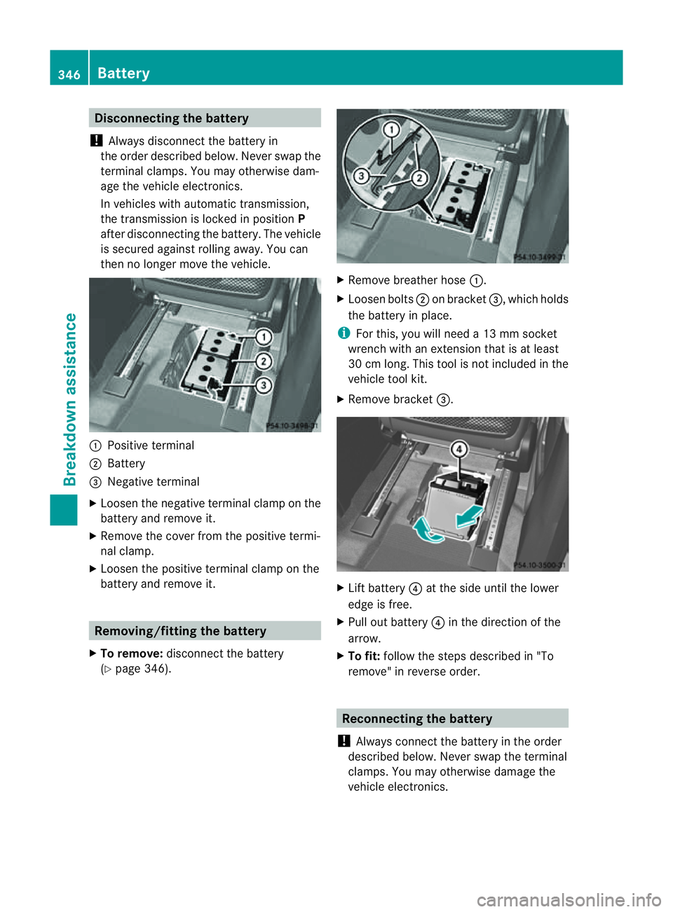
then no longer mov ethe vehicle. :
Positive termi nal
; Battery
= Negative terminal
X Loosen the negative terminal clamp on the
battery and remove it.
X Remove the cover from the positive termi-
nal clamp.
X Loosen the positive terminal clamp on the
battery and remove it. Removing/fitting the battery
X To remove: disconnect the battery
(Y pag e346). X
Remove breather hose :.
X Loose nbolts ;on bracket =,which holds
the battery in place.
i For this, you will need a13mmsocket
wrenc hwith an extension that is at least
30 cm long. This tool is not included in the
vehicle tool kit.
X Remove bracket =. X
Lif tb attery ?at the side until the lower
edge is free.
X Pull out battery ?in the direction of the
arrow.
X To fit: follow the steps described in "To
remove" in reverse order. Reconnecting the battery
! Always connect the battery in the order
described below. Never swap the terminal
clamps. You may otherwise damage the
vehicle electronics. 346
BatteryBreakdown assistance
Page 350 of 389

X
Switch off al lelec trical consumers (e.g.
radio ,blow er, etc.).
X Connec tthe positive terminal clamp and
secure the cov er.
X Connect the negative terminal clamp.
i If the power supply ha sbeeninterrupted,
e.g. if yo ureconnect the battery, you will
have to:
R set the clock; see the separate operat ing
instructions.
R rese tthe function for automatically fold-
ing the exterior mirror sin/out by foldi ng
the mirrors out onc e(Ypage 10 1). Charging th
ebattery G
WARNING
Onl ycharge the battery in awell-ventilated
area .Ast he battery is being charged, gases
can escap eand generat eminor explosions.
This could injure you and other person sor
caus edamage to the paintwork or acid cor-
rosion on the vehicle.
You can obtain information about battery
chargers which allow the batter ytobe
charged while still installed from aqualified
specialist workshop ,e.g. aM ercedes-Benz
Ser vice Centre. G
WARNING
There is arisk of acid burns during the charg-
ing process due to the gases which escape
from the battery. Do not lean over the battery
during the chargin gprocess. G
WARNING
Battery aci discaustic. Avoid contact with the
skin, eyes or clothing.
! Only charge the installed batter ywith a
batter ycharger whic hhas been tested and
approved by Mercedes -Benz .These battery
chargers allow the battery to be charged
while still installed. !
Only use battery chargers with amaxi-
mum charging voltage of 14.8 V.
! Only charge the battery using the jump-
start connection point.
The jump-starting connection point is in the
engine compartmen t(Ypage 348).
X Open the bonnet (Y page 318).
X Connec tthe battery charger to the positive
terminal and earth point in the sam eorder
as when connecting th edonor battery in
the jump-startin gprocedure
(Y page 348).
X Read th ebattery charger's operating
instructions before charging the battery. Battery
347Breakdown assistanc e Z