2011 MERCEDES-BENZ G550 remote start
[x] Cancel search: remote startPage 10 of 288

Exterior viewOverview .......................................... 24
F
First-aid kit ......................................... 229
Flat tire Changing a wheel/mounting the
spare wheel ................................... 232
Preparing the vehicle .....................232
Raising the vehicle .........................233
Floormat ............................................. 211
Front fog lamp (display message) ... 173
Fuel Additives ........................................ 278
Notes ............................................. 277
Premium-grade unleaded gasoline . 278
Refueling ........................................ 131
Specifications ................................ 278
Troubleshooting ............................. 134
Fuel/water separator ....................... 220
Fuel consumption Notes ............................................. 136
Fuel filler cap (display message) ..... 178
Fuel filler flap Emergency release ........................133
Opening/closing ............................ 132
Fuel filter
Display message ............................ 178
Fuel level
Calling up the range (on-board
computer) ...................................... 167
Fuse allocation chart ........................ 243
Fuse box Battery case ................................... 244
Dashboard ..................................... 243
Front-passenger footwell ...............243
Transmission tunnel ....................... 244
Fuse extractor ................................... 243
Fuses Dashboard fuse box .......................243
Fuse allocation chart .....................243
Fuse box in the front-passenger
footwell .......................................... 243
Fuse box in the transmission
tunnel ............................................ 244
In the battery case .........................244
Notes ............................................. 242
G
Garage door opener Clearing the memory .....................211
Notes ............................................. 208
Opening/closing the garage door ..210
Programming the remote control ...209
Gear or selector lever (cleaning
guidelines) ......................................... 225
Genuine Mercedes-Benz parts ......... 274
Genuine wood trim and trim strips
(cleaning instructions) ...................... 225
Glove box ........................................... 193
Gradient-climbing capability
(maximum) ......................................... 146
GTW (Gross Trailer Weight)
(definition) ......................................... 267
H
Hazard warning lamps ........................ 93
Headlamp cleaning system ................ 93
Adding washer fluid .......................218
Notes ............................................. 281
Headlamp delayed switch-off
see Exterior lighting delayed switch-off
Headlamp protection grille .............. 100
Headlamps Cleaning ......................................... 224
Misting up ........................................ 94
Headlamps (automatic) ...................... 91
Head restraints Adjusting (angle) .............................. 79
Adjusting (rear) ................................ 80
Installing/removing (rear) ................80
Luxury .............................................. 80
Resetting (front) ............................... 80
see NECK-PRO head restraints
Heating
see Climate control ........................ 106
High beam flasher ............................... 93
high-mounted brake lamp Display message ............................ 173
Hill start assist .................................. 118
Hood Closing ........................................... 215
Display message ............................ 181
Opening ......................................... 214
8Index
Page 16 of 288

System .......................................... 202
Vehicle remote unlocking ..............206
Telephone
Menu (on-board computer) ............167
Telephone compartment .................. 193
Temperature Coolant .......................................... 156
Displaying the outside
temperature ................................... 160
Outside temperature ...................... 157
Setting (climate control) ................109
Theft deterrent locking system
Immobilizer ...................................... 59
Tilt/sliding sunroof
see Sliding sunroof
Tire pressure
Calling up (on-board computer) .....253
Checking ........................................ 252
Checking manually ........................253
Display message ............................ 179
Maximum ....................................... 252
Notes ............................................. 250
Recommended ............................... 249
Tire pressure monitoring system
Function/notes ............................. 253
Restarting ...................................... 255
Warning lamp ................................. 189
Tires
Aspect ratio (definition) .................268
Average weight of the vehicle
occupants (definition) ....................267
Bar (definition) ............................... 266
Characteristics .............................. 266
Checking ........................................ 246
Definition of terms .........................266
Direction of rotation ......................270
Distribution of the vehicle
occupants (definition) ....................269
DOT, Tire Identification Number
(TIN) ............................................... 265
DOT (Department of
Transportation) (definition) ............266
GAWR (Gross Axle Weight Rating)
(definition) ..................................... 267
GTW (Gross Trailer Weight)
(definition) ..................................... 267
GVW (Gross Vehicle Weight)
(definition) ..................................... 267GVWR (Gross Vehicle Weight
Rating) (definition) .........................267
Increased vehicle weight due to
optional equipment (definition) ......267
Kilopascal (kPa) (definition) ...........268
Labeling (overview) ........................262
Load bearing index (definition) ......269
Load index ..................................... 265
Load index (definition) ...................268
Maximum loaded vehicle weight
(definition) ..................................... 267
Maximum load on a tire
(definition) ..................................... 268
Maximum permissible tire
pressure (definition) ....................... 268
Maximum tire load .........................260
Maximum tire load (definition) .......268
Optional equipment weight
(definition) ..................................... 268
PSI (pounds per square inch)
(definition) ..................................... 268
Replacing ....................................... 269
Service life ..................................... 248
Sidewall (definition) .......................268
Speed index (definition) .................267
Storing ........................................... 270
Structure and characteristics
(definition) ..................................... 266
Technical data ............................... 272
Temperature .................................. 262
TIN (Tire Identification Number)
(definition) ..................................... 269
Tire bead (definition) ......................268
Tire pressure (definition) ................268
Tire pressures (recommended) ......267
Tire size designation, load-bearing
capacity, speed index ....................263
Tire tread ....................................... 247
Tire tread (definition) .....................268
Total load limit (definition) .............269
Traction ......................................... 261
Traction (definition) .......................269
Tread wear ..................................... 261
TWR (permissible trailer drawbar
noseweight) (definition) .................269
Uniform Tire Quality Grading
Standards ...................................... 26114Index
Page 208 of 288

Failed message appears in the
multifunction display.XTo end a call: press the ~ button on the
multifunction steering wheel.
or
XPress the corresponding button for ending
a phone call on COMAND.
Call priority
When service calls are active, e.g. Roadside
Assistance or MB Info calls, an emergency
call can still be initiated. In this case, an
emergency call has the highest priority and
takes precedence over all other active calls.
The indicator lamp of the respective button
flashes until the call is ended. An emergency
call can only be terminated by the Response
Center. All other calls can be ended by
pressing the ~ button on the
multifunction steering wheel or the
corresponding button for ending a telephone
call on COMAND.
i When an mbrace call has been initiated,
COMAND is muted. The mobile phone is no
longer connected to COMAND. However, if
you want to use your mobile phone, we
recommend that you do this only when the
vehicle is stationary and in a safe location.
Downloading destinations in COMAND
i Information on the components and
operating principles of the COMAND
system can be found in the separate
COMAND operating instructions.
Destination Download gives you access to a
database with over ten million points of
interest (POIs) which can be downloaded onto
the navigation system of your vehicle. If you
know the destination, you can download the
address or obtain the location of points of
interest (POIs) or important destinations in
the surrounding area.
You are prompted to confirm route guidance
to the address entered.XSelect Yes using the = or ; button
on COMAND.XPress 9 on COMAND to confirm.
The system calculates the route and
subsequently starts the route guidance with
the address entered.
i If you select No, the address can be stored
in the address book.
i The Destination Download function is
available if the corresponding mobile
phone network is available and data
transfer is possible.
Search & Send
"Search & Send" is a destination entry
service. You can find further information on
"Search & Send" in the separate COMAND
operating instructions.
Vehicle remote unlocking
If you have unintentionally locked your
vehicle (e.g. the SmartKey is inside the
vehicle) and a replacement key is not
available:
XContact the following service hotlines:
R USA: Response Center at
1-888-990-9007
R Canada: Customer Service at
1-888-923-8367
You will be asked for your password.XReturn to your vehicle at the time arranged
with the Response Center.XPress and hold the release button on the
rear door handle for at least 20 seconds
until the indicator lamp in the SOS button
( Y page 203) begins flashing.
The Connecting Call message appears
on the multifunction display.
Alternatively, the vehicle can also be opened
via the Internet in the "Owners Online"
206FeaturesLoading, stowing and features
Page 211 of 288

Programming the remote control
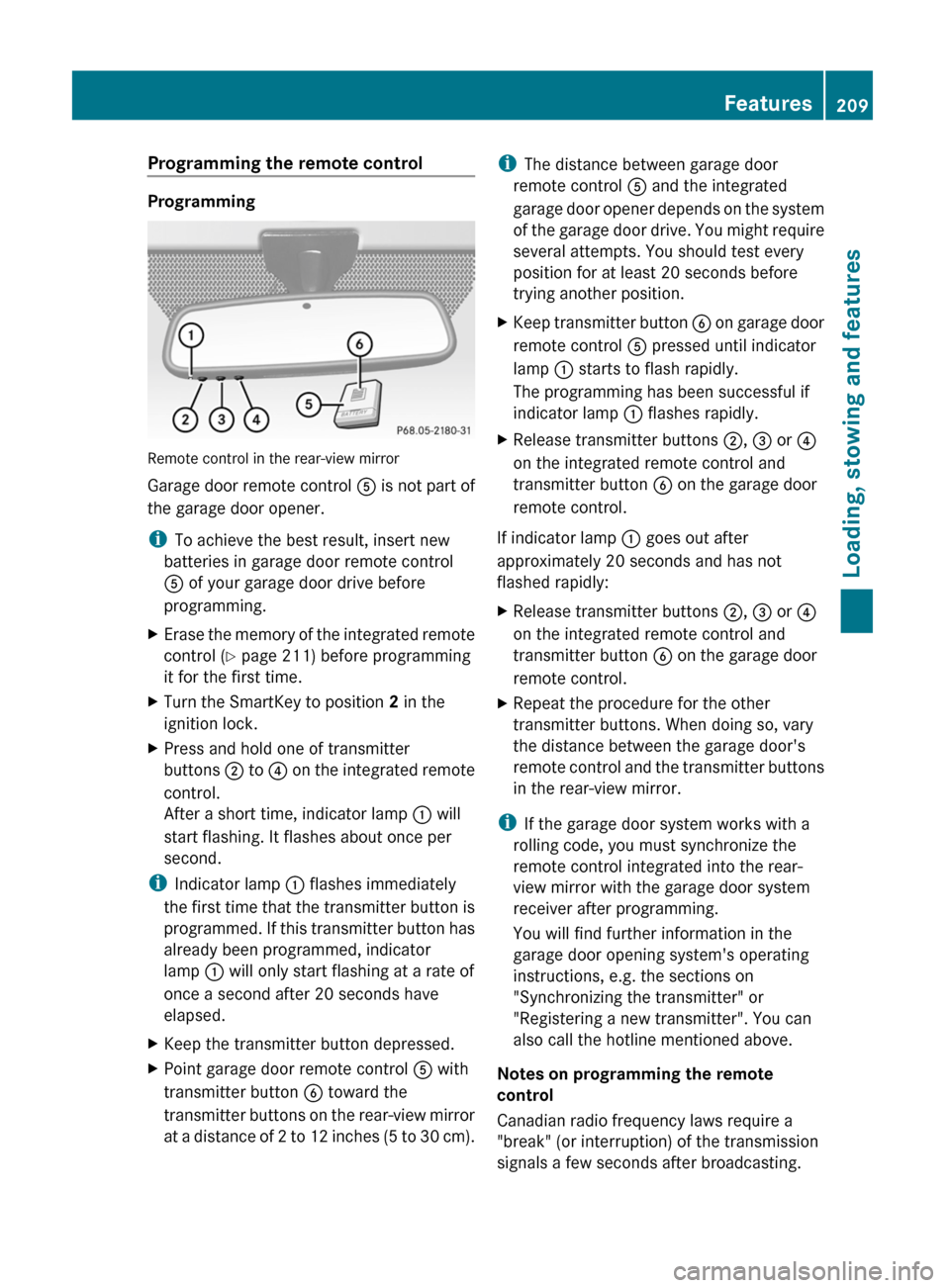
Programming
Remote control in the rear-view mirror
Garage door remote control A is not part of
the garage door opener.
i To achieve the best result, insert new
batteries in garage door remote control
A of your garage door drive before
programming.
XErase the memory of the integrated remote
control ( Y page 211) before programming
it for the first time.XTurn the SmartKey to position 2 in the
ignition lock.XPress and hold one of transmitter
buttons ; to ? on the integrated remote
control.
After a short time, indicator lamp : will
start flashing. It flashes about once per
second.
i Indicator lamp : flashes immediately
the first time that the transmitter button is
programmed. If this transmitter button has
already been programmed, indicator
lamp : will only start flashing at a rate of
once a second after 20 seconds have
elapsed.
XKeep the transmitter button depressed.XPoint garage door remote control A with
transmitter button B toward the
transmitter buttons on the rear-view mirror
at a distance of 2 to 12 inches (5 to 30 cm).i The distance between garage door
remote control A and the integrated
garage door opener depends on the system
of the garage door drive. You might require
several attempts. You should test every
position for at least 20 seconds before
trying another position.XKeep transmitter button B on garage door
remote control A pressed until indicator
lamp : starts to flash rapidly.
The programming has been successful if
indicator lamp : flashes rapidly.XRelease transmitter buttons ;, = or ?
on the integrated remote control and
transmitter button B on the garage door
remote control.
If indicator lamp : goes out after
approximately 20 seconds and has not
flashed rapidly:
XRelease transmitter buttons ;, = or ?
on the integrated remote control and
transmitter button B on the garage door
remote control.XRepeat the procedure for the other
transmitter buttons. When doing so, vary
the distance between the garage door's
remote control and the transmitter buttons
in the rear-view mirror.
i If the garage door system works with a
rolling code, you must synchronize the
remote control integrated into the rear-
view mirror with the garage door system
receiver after programming.
You will find further information in the
garage door opening system's operating
instructions, e.g. the sections on
"Synchronizing the transmitter" or
"Registering a new transmitter". You can
also call the hotline mentioned above.
Notes on programming the remote
control
Canadian radio frequency laws require a
"break" (or interruption) of the transmission
signals a few seconds after broadcasting.
Features209Loading, stowing and featuresZ