Page 142 of 353

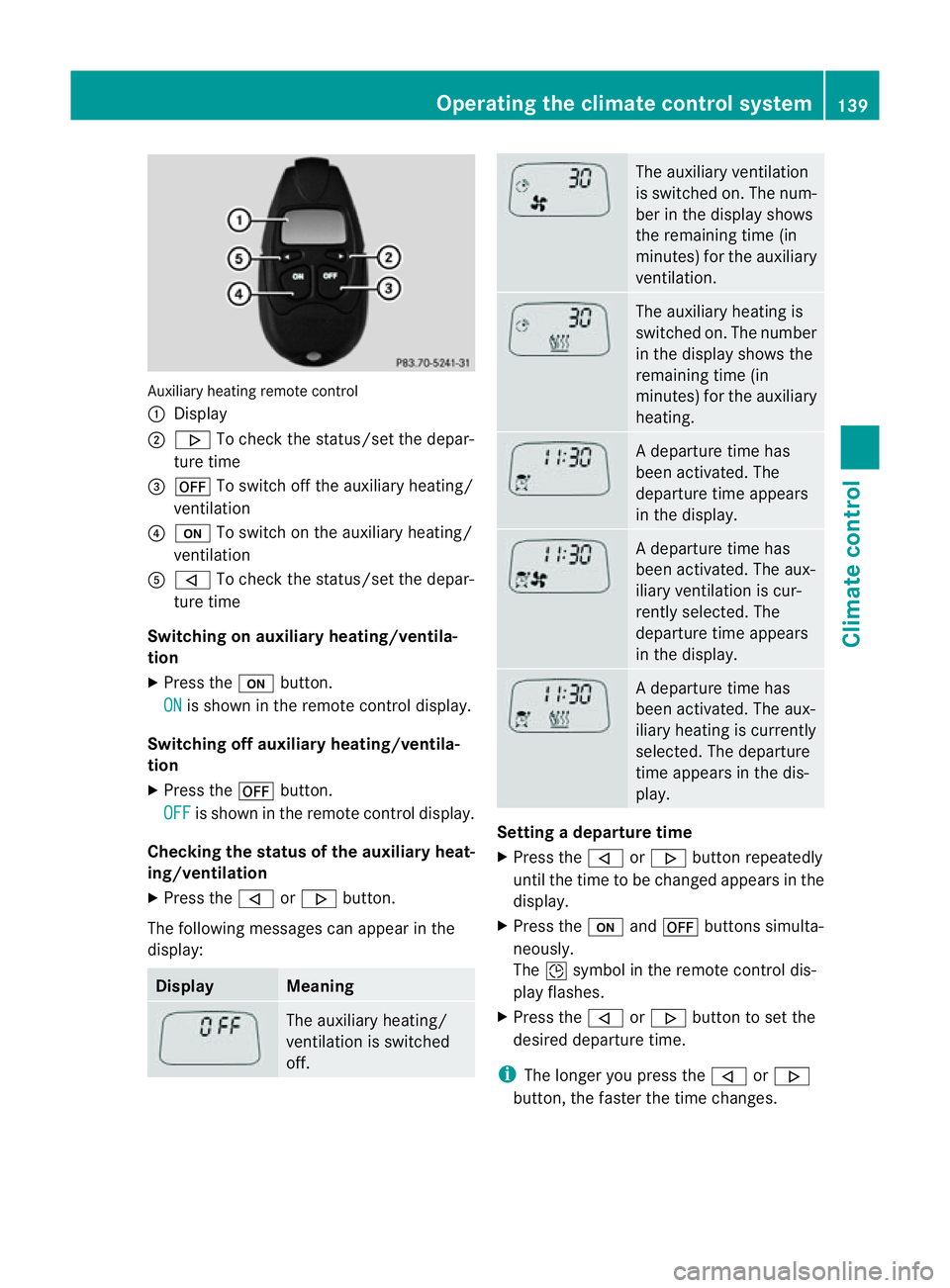
Auxiliary heating remote control
:
Display
; . To chec kthe status/set the depar-
ture time
= ^ To switch off the auxiliary heating/
ventilation
? u To switch on the auxiliary heating/
ventilation
A , To check the status/set the depar-
ture time
Switching on auxiliary heating/ventila-
tion
X Press the ubutton.
ON is shown in the remote control display.
Switching off auxiliary heating/ventila-
tion
X Press the ^button.
OFF is shown in the remote control display.
Checking the status of the auxiliary heat-
ing/ventilation
X Press the ,or. button.
The following messages can appearint he
display: Display Meaning
The auxiliary heating/
ventilation is switched
off. The auxiliary ventilation
is switched on. The num-
ber in the displays
hows
the remaining time (in
minutes) for the auxiliary
ventilation. The auxiliary heating is
switched on. The number
in the displays
hows the
remaining time (in
minutes) for the auxiliary
heating. Ad
eparture time has
been activated. The
departure time appears
in the display. Ad
eparture time has
been activated. The aux-
iliary ventilation is cur-
rently selected. The
departure time appears
in the display. Ad
eparture time has
been activated. The aux-
iliary heating is currently
selected. The departure
time appears in the dis-
play. Setting
adeparture time
X Press the ,or. button repeatedly
until the time to be changed appears in the
display.
X Press the uand^ button ssimulta-
neously.
The Îsymbol in the remot econtrol dis-
play flashes.
X Press the ,or. button to set the
desired departure time.
i The longer you press the ,or.
button ,the faster the time changes. Operating thec
limatecontrol system
139Climatecontrol Z
Page 143 of 353

X
Press the uand^ button ssimulta-
neously.
The new departure time is stored.
Activating aset departuret ime
X Press the ,or. button repeatedly
until the desired departure time appears in
the display.
X Press the ubutton.
The Ísymbol and the departure time
appear in the display.
Deactivating aset departuret ime
X Press the ,or. button.
The status of the auxiliary heating is shown
in the display.
X Press the .button.
The first departure time stored appears in
the display.
X Press the ^button.
The display message OFF appears in the
display.
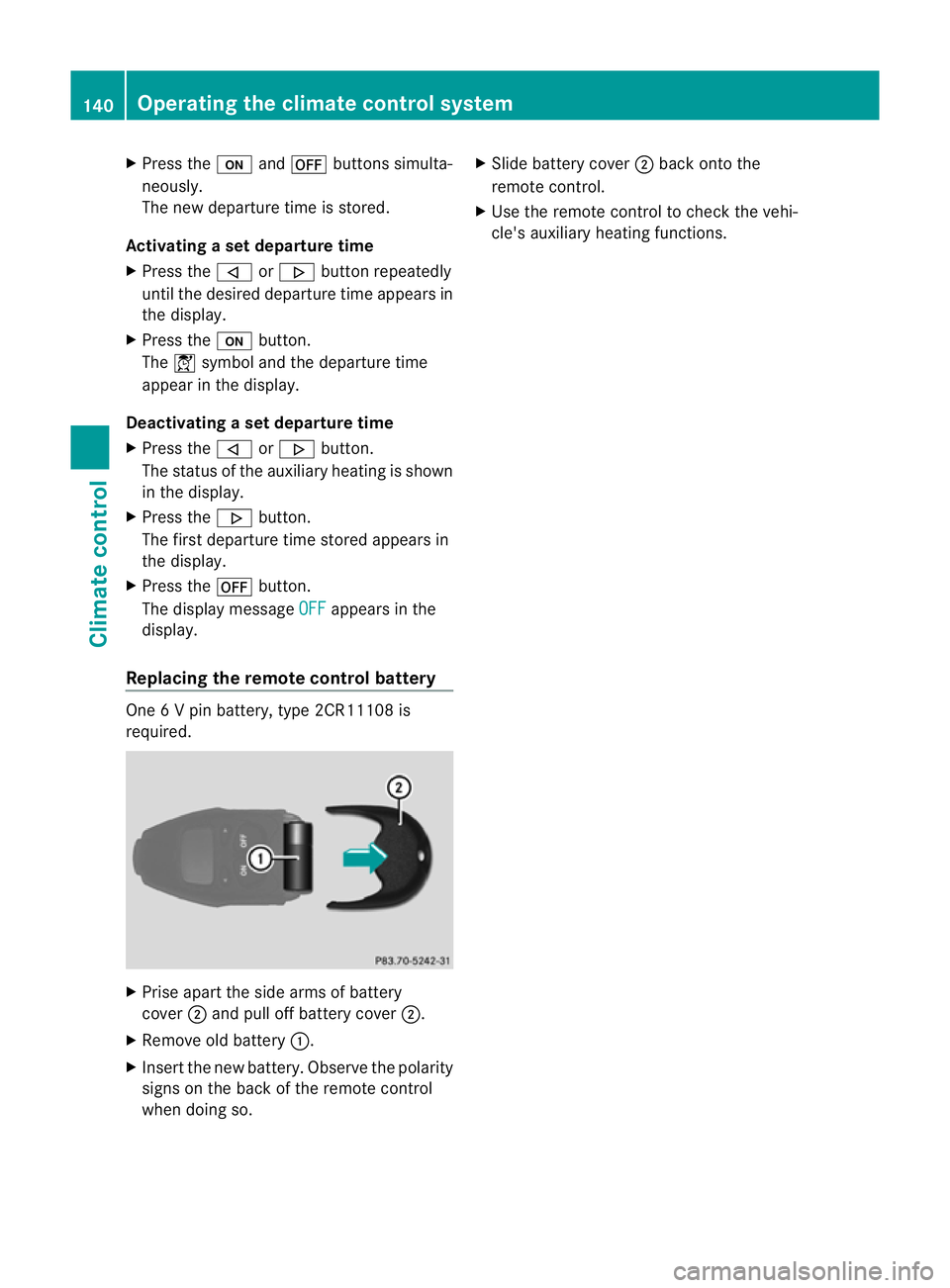
Replacing the remot econtrol battery One
6Vp in battery, type 2CR11108 is
required. X
Prise apart the side arms of battery
cover ;and pull off batter ycover ;.
X Remove old battery :.
X Inser tthe new battery. Observe the polarity
signs on the back of the remote control
when doing so. X
Slide battery cover ;back onto the
remote control.
X Use the remote control to check the vehi-
cle's auxiliary heating functions. 140
Operating the climate control systemClimatec
ontrol
Page 144 of 353

Problems with the auxiliary heating/ventilation
Display messages Possible causes/consequences and
M Solutions
FAIL The starter battery is not charged sufficiently or the system is
faulty.
X
Charge the starter battery.
X Make another attempt to switch on the auxiliary heating using
the remote control.
X Have the auxiliary heating checked at aqualified specialist
workshop. $
FAIL The signal transmission between the transmitter and the vehicle
is faulty.
X
Change your position in relation to the vehicle, moving closer if
necessary.
X Make another attempt to switch the auxiliary heating on or off
using the remote control. ©
FAIL There is not enough fuel in the fuel tank,ort
he auxiliary heating
is faulty.
X Refuel at the nearest filling station.
X Make another attempt to switch on the auxiliary heating using
the remote control.
X Have the auxiliary heating checked at aqualified specialist
workshop. Adjusting the air vents
Important safety notes
G
WARNING
Very hot or very cold air can flow from the air
vents. This could cause burns or frostbit eto
bare skin in the immediate vicinity of the
vents. Keep bare skin away from these air
outlets. If necessary, direct the airflow away
to ad ifferent area of the vehicle interior. In order to ensure the direct flow of fresh air
through the air ventsi
nto the vehicle interior,
please observe the following notes:
R keep the air inlet between the windscreen
and the bonnet free of blockages, such as
ice, snow or leaves
R never cover the ventsora ir inlets in the
vehicle interior.
i For virtually draught-free ventilation,
adjust the sliders of the air ventstot he
centre position. Adjusting the air vents
141Climate control Z
Page 145 of 353

Setting the centre air vents
:
Centre air vent,l eft
; Centre air vent,r ight
= Centre vent thumbwheel, right
? Centre vent thumbwheel, left
X To open/close: turn thumbwheels =
and ?up or down. Setting the side air vents
X
To open/close: turn thumbwheel =up or
down.
i Side window demister vent :is never
completely shut, even if side air vent ;is
shut. Setting the glove compartment air
vent
When automatic climate control is activated,
the glove compartmen tcan be ventilated, for
instance to cool its contents .The level of air- flow depends on the airflow and air distribu-
tion settings.
!
Close the air vent when heating the vehi-
cle.
At high outside temperatures, open the air
vent and activate the "cooling with air dehu-
midification" function. Otherwise, temper-
ature-sensitive items stored in the glove
compartmentc ould be damaged. :
Air vent thumbwheel
; Air vent
X To open/close: turn thumbwheel :
clockwise or anti-clockwise. Setting the rear-compartment air
vents
Setting the centre vents in the rear com-
partment :
Rear-compartment air vent thumbwheel
; Rear-compartment air vent,r ight142
Adjusting the air ventsClimate control
Page 146 of 353
=
Rear control panel for THERMOTRONIC
automatic climat econtrol
? Rear-compartmen tair vent, left
X To open/close: turnthumbwheel :up or
down. Setting the AIRSCARF vents
G
WARNING
Very hot air can flow out of the AIRSCARF
vents in the head restraintsw hen AIRSCARF
is in operation. This can cause burns on unpro-
tected skin near the AIRSCARF vents. Lower
the heating output in good time, when neces-
sary. You can adjust the blower output of AIR-
SCARF vents :using the AIRSCARF button
(Y page 107). Adjusting the air vents
143Climatecontrol Z
Page 165 of 353

Diesel (EN 590)
Fuel grade !
Whe nrefuelling, only use diesel fuel that
conforms to the European standard EN 590
or is of equivalent quality. You can other-
wise impair engin eoutput or damage the
engine.
! Vehicles with diesel particle filters: in
countries outside the EU, only use low sul-
phur Euro diesel with asulphur contentof
under 50 ppm .Otherwise, the emission
control syste mcould be damaged.
! Vehicles without adiesel particle fil-
ter: in countries where only diesel fuels
with ahigher sulphur conten tare available,
the vehicle's oil change interval sare
shorter. More information about intervals
for changing the oil can be obtained from
any Mercedes-Benz Service Centre.
! Only use fuel that complies with the EN
590 European standard .Fuel that does not
comply wit hEN590can lead to increased
wear, engin edamag eand damag etothe
exhaust system.
Do not use the following:
R marine diesel
R heating oil
R bio-diesel
R vegetable oil
R petrol
R paraffin
R kerosene
Do not mix these fuels with diesel fuels and
do not use any special additives. Other-
wise, this can lead to damage to the engine.
This excludes flow improver; see "Low out-
side temperatures".
! Use afilter when adding fuel from afuel
can. Otherwise, the fuel lines and/or the
diesel injection system could be blocked by
particles from the fuel can. For further information on "Fuel", see
(Y
page 334).
Low outside temperatures Diesel fuel with improved cold flow qualities
is available during the winter months. In
Europe, various climate-dependent low-tem-
perature classes are defined in EN 590. Refu-
elling with diesel fuel which complies with the
climatic specification sofstandard EN 590
can help to prevent operating problems. At
exceptionally low temperatures, it is possible
that the flow properties of the fuel may be
inadequate. This also applies to fuel that has
not been adapted to suit the climatic condi-
tions, e.g. diesel fuel from warmer regions.
i Further information about country-spe-
cific fuel properties can be obtained from
oil companies, e.g. at filling stations.
Flow improver Flow improvers can be added to improve the
cold resistanc
eofdiesel fuel. The effective-
ness of aflow improver is not guaranteed with
every fuel.
Correct dosage and thorough mixing are deci-
sive factor sinensuring improvement in low-
temperature resistance. Under certain cir-
cumstances, an excessive dosage may
actually decrease low-temperature resist-
ance and should therefor ebeavoided. Follow
the manufacturer's dosing instructions.
Mix the additive with the diesel in good time,
before the flow properties of the diesel
become inadequate. Malfunction scan other-
wise only be rectified by heating the entire
fuel system, e.g. by parking the vehicle in a
heated garage.
Observe the information provided by the man-
ufacturer when using aflow improver. Only
use flow improvers that have been tested and
approved by Mercedes-Benz. You can obtain
further information from any Mercedes-Benz
Servic eCentre. 162
RefuellingDriving and parking
Page:
< prev 1-8 9-16 17-24