2011 MERCEDES-BENZ C-CLASS COUPE display
[x] Cancel search: displayPage 99 of 373

Useful information
i This Owner's Manual describes all models
and all standard and optional equipment
available to your vehicle at the time of pub-
lication of the Owner's Manual. Country-
specific deviations are possible. Please
note that your vehicle may not be equipped
with all features described. This also
applies to safety-relevan tsystems and
functions.
i Please read the information on qualified
specialist workshops (Y page 26).Correct driver's sea
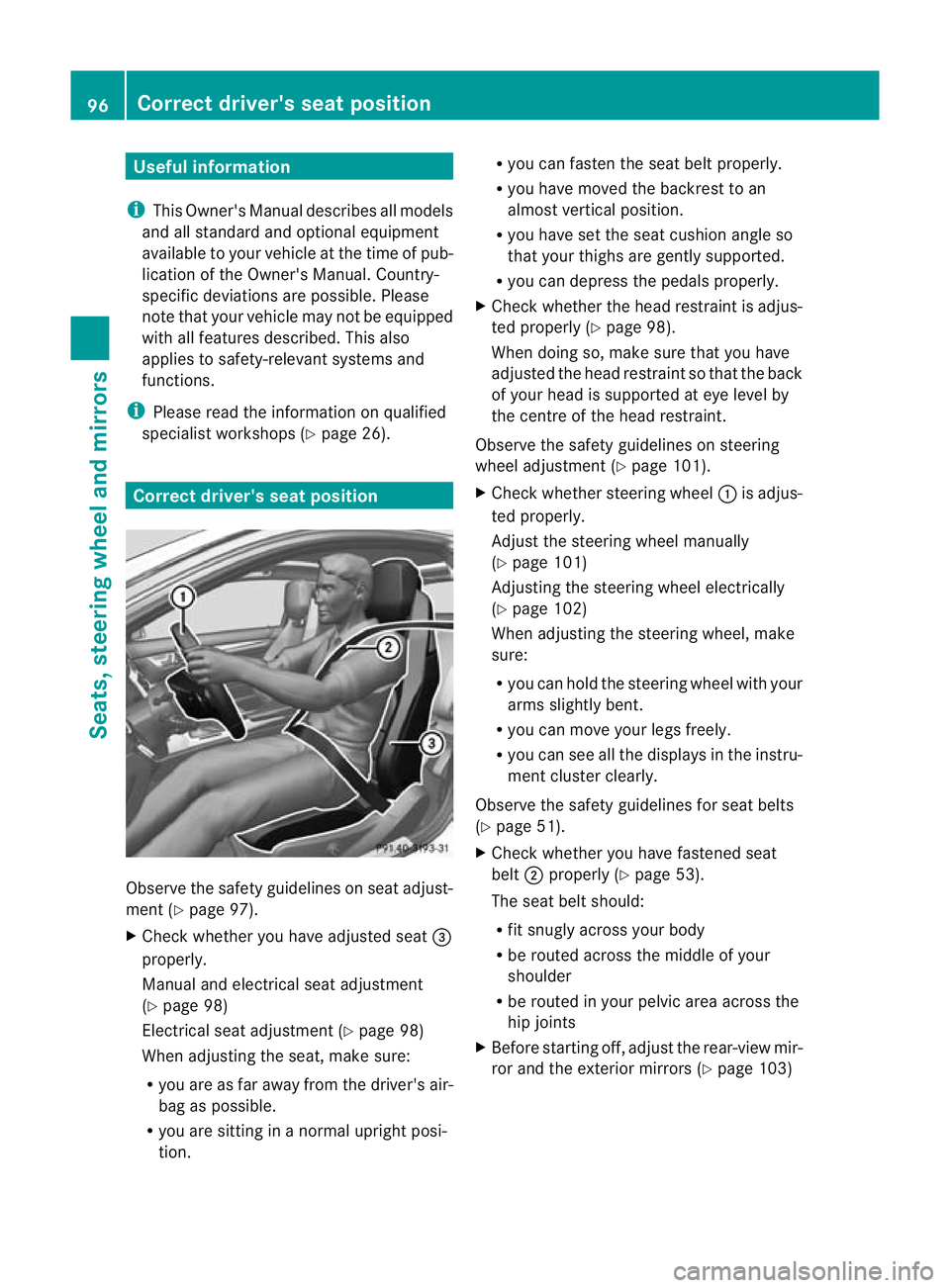
tposition Observe the safety guidelines on seat adjust-
ment (Y
page 97).
X Chec kwhether you have adjusted seat =
properly.
Manual and electrical seat adjustment
(Y page 98)
Electrical seat adjustment (Y page 98)
When adjusting the seat, make sure:
R you are as far away from the driver's air-
bag as possible.
R you are sitting in a normal upright posi-
tion. R
you can fasten the seat belt properly.
R you have moved the backrest to an
almost vertical position.
R you have set the seat cushion angle so
that your thighs are gently supported.
R you can depress the pedals properly.
X Check whether the head restraint is adjus-
ted properly (Y page 98).
When doing so, make sure that you have
adjusted the head restraint so that the back
of your head is supported at eye level by
the centre of the head restraint.
Observe the safety guidelines on steering
wheel adjustment (Y page 101).
X Check whether steering wheel :is adjus-
ted properly.
Adjust the steering wheel manually
(Y page 101)
Adjusting the steering wheel electrically
(Y page 102)
When adjusting the steering wheel, make
sure:
R you can hold the steering wheel with your
arms slightly bent.
R you can move your legs freely.
R you can see all the displays in the instru-
ment cluster clearly.
Observe the safety guidelines for seat belts
(Y page 51).
X Check whether you have fastened seat
belt ;properly (Y page 53).
The seat belt should:
R fit snugly across your body
R be routed across the middle of your
shoulder
R be routed in your pelvic area across the
hip joints
X Before starting off, adjust the rear-view mir-
ror and the exterior mirrors (Y page 103)96
Correct driver's seat positionSeats, steering wheel and mirrors
Page 102 of 373

Adjusting the head restraints electri-
cally X
To adjust th ehead restraint height: slide
the switch for head restrain tadjustment
(Y page 98) up or down in the direction of
the arrow. Folding the front-seat backrests
forward/back
Important safety notes G
WARNING
Make sure that the backrest engages fully. If
the backrest is not engaged, the message:
Front right seat backrest not locked or
Front left seat backrest not locked appears in the multifunction display.
Stop the vehicle as soon as road and traffic
conditions permit and remove any objects
that are blocking the backrest. G
WARNING
Make sure that nobody can become trapped
when moving the seat. If there is a risk of
someone becoming trapped, press the seat
adjustment switch on the door.
Folding the backrest forwards With the EASY-ENTRY feature, the seat moves
forwards if you have folded the backrest for-
wards and the seat is in the rear half of the
adjustment range. This makes it easier for
passengers to get into and out of the rear
compartment.
The head restraint also lowers on vehicles
with electric seat adjustment. X
Vehicles without memory function:
release the head restraint if necessary and
push it down.
X Pull seat release handle :forwards and
fold the backrest forwards until the seat
backrest engages.
X Push the seat as far forwards as it will go.
X Vehicles with memory function: pull seat
release handle :forwards and fold the
backrest forwards as far as it will go.
The seat moves automatically to the fore-
most position.
Folding back the backrest X
Vehicles without memory function:
push the seat backrest back horizontally
until the seat reaches the position that was
previously set.
X Fold the seat backrest backwards until you
hear it engage. Do so in a smooth manner.
X After the seat backrest has been folded
back, chec kthe position of the head
restraint and set it to the correct position.
X Vehicles with memory function: swing
back the seat backrest.
The seat moves automatically to the stored
position. Adjusting the 4-way lumbar support
You can adjust the contour of the front seat
backrests individually to provide optimum
support for your back. Seats
99Seats, steering wheel and mirrors Z
Page 128 of 373

X
Turn the key to position 2in the ignition
lock.
X Set the desired temperature.
X To activate: press theÃbutton.
The indicator lamp in the Ãbutton lights
up. Automatic air distribution and airflow
are activated.
X To switch off: press the_button.
or
X Press the KorI button.
The indicator lamp in the Ãbutton goes
out. Automatic air distribution and airflow
are deactivated. Setting the temperature
Different temperatures can be set for the
driver's and front-passenger sides.
X Turn the key to position 2in the ignition
lock.
X To increase/reduce: turn controls:and
B clockwise or anti-clockwise
(Y page 123).
Only change the temperature setting in
small increments. Start at 22 †. Setting the air distribution
Air distribution settings P
Directs the airflow through the centre
and side air vents
O Directs the airflow through the foot-
well air vents
S Directs the airflow through the centre
and side air vents and the footwell air
vents
¯ Directs the airflow through the demis-
ter vents
b Directs the airflow through the centre
and side air vents as well as the demis-
ter vents a
Directs the airflow through the foot-
well and demister vents
_ Directs the airflow through the demis-
ter, centre and side air vents as well as
the footwell air vents
i Regardless of the air distribution setting,
airflow is always directed through the side
air vents. The side air vents can only be
closed when the controls on the side air
vents are turned downwards.
X Turn the key to position 2in the ignition
lock.
X Press the _button repeatedly until the
desired symbol appears in the display.
The indicator lamp in the Ãbutton goes
out. Automatic control is deactivated and
the air distribution is controlled according
to the selected setting. Setting the airflow
X Turn the key to position 2in the ignition
lock.
X To increase/reduce: press theKor
I button. Switching the ZONE function on/off
X To switch on: press theábutton.
The indicator lamp in the ábutton lights
up.
The temperature setting for the driver's
side is not adopted for the front-passenger
side.
When the buttons for temperature, airflow or
air distribution are activated, the temperature
setting for the driver's side is not adopted for
the other climate control zones.
X To switch off: press theábutton.
The indicator lamp in the ábutton goes
out. Operating the climate control system
125Climate control Z
Page 132 of 373

Switching on auxiliary heating/ventila-
tion
X
Press button :.
The red or blue indicator lamp in but-
ton :lights up.
Switching off auxiliary heating/ventila-
tion
X Press button :.
The red or blue indicator lamp in but-
ton :goes out.
Switching the auxiliary heating/venti-
lation on/off using the remote control Your vehicle comes with one remote control.
You may use two additional remote controls
for your vehicle. For further information, con-
sult a qualified specialist workshop, e.g. a
Mercedes-Benz Service Centre.
The remote control has a maximum range of
approximately 300 metres. This range is
reduced by:
R sources of radio interference
R solid objects between the remote control
and the vehicle
R the remote control being in an unfavoura-
ble position in relation to the vehicle
R transmitting from an enclosed space
i The optimum range can be achieved if you
hold the remote control vertically, pointing
upwards when you press one of the but-
tons.
i Abattery symbol appears in the display
when the battery in the remote control is
low. Replace the remote control battery
(Y page 130). Auxiliary heating remote control
:
Display
; . To check the status/set the depar-
ture time
= ^ To switch off the auxiliary heating/
ventilation
? u To switch on the auxiliary heating/
ventilation
A , To check the status/set the depar-
ture time
Switching on auxiliary heating/ventila-
tion
X Press the ubutton.
ON is shown in the remote control display.
Switching off auxiliary heating/ventila-
tion
X Press the ^button.
OFF is shown in the remote control display.
Checking th estatus of the auxiliary heat-
ing/ventilation
X Press the ,or. button.
The following messages can appear in the
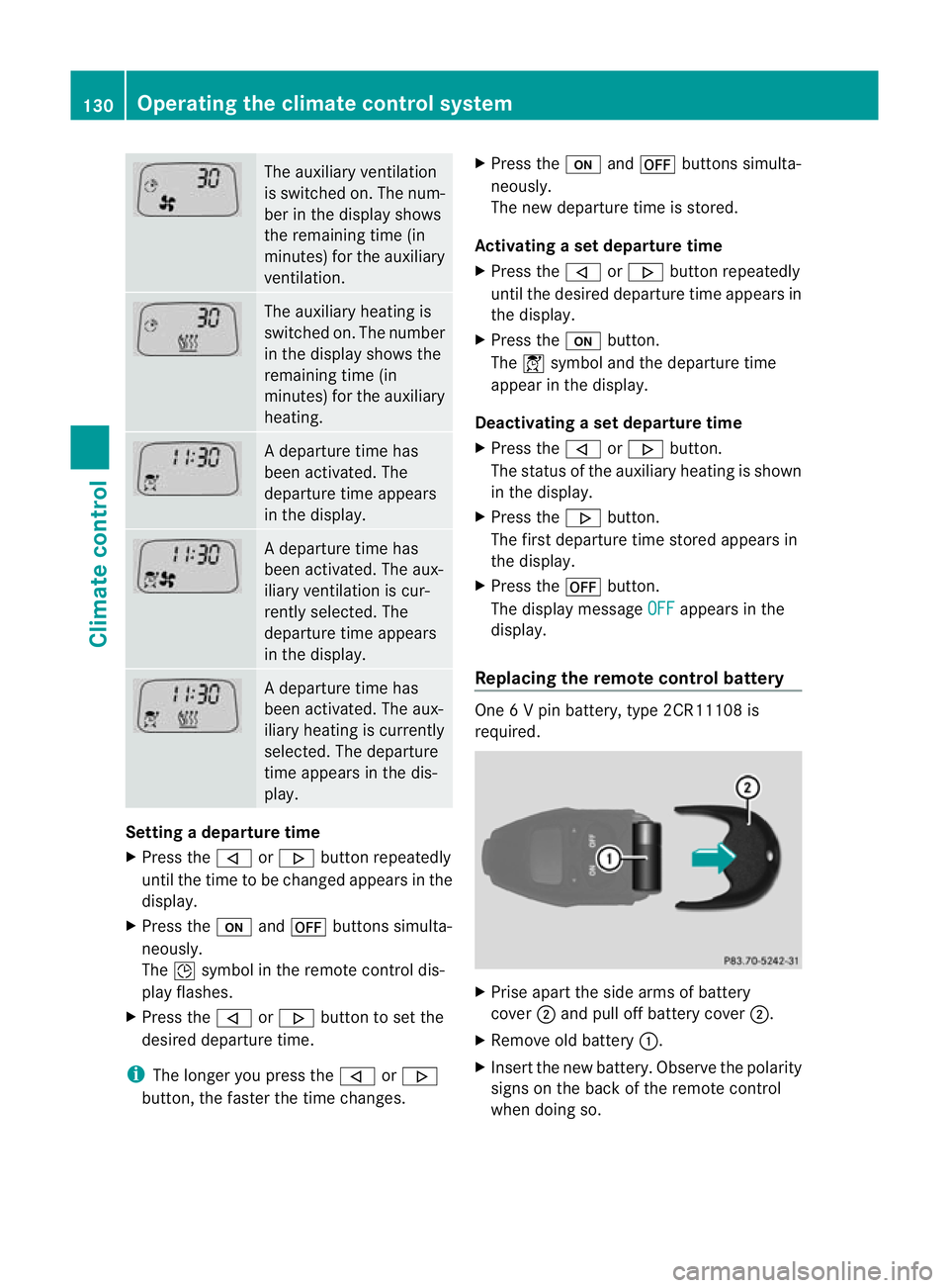
display: Display Meaning
The auxiliary heating/
ventilatio
nis switched
off. Operating the climate control system
129Climate control Z
Page 133 of 373

The auxiliary ventilation
is switched on. The num-
ber in the display shows
the remaining time (in
minutes) for the auxiliary
ventilation.
The auxiliary heating is
switched on. The number
in the display shows the
remaining time (in
minutes) for the auxiliary
heating.
Ad
eparture time has
been activated. The
departure time appears
in the display. Ad
eparture time has
been activated. The aux-
iliary ventilation is cur-
rently selected. The
departure time appears
in the display. Ad
eparture time has
been activated. The aux-
iliary heating is currently
selected. The departure
time appears in the dis-
play. Setting a departure time
X
Press the ,or. button repeatedly
until the time to be changed appears in the
display.
X Press the uand^ buttons simulta-
neously.
The Îsymbol in the remote control dis-
play flashes.
X Press the ,or. button to set the
desired departure time.
i The longer you press the ,or.
button, the faster the time changes. X
Press the uand^ buttons simulta-
neously.
The new departure time is stored.
Activating a set departure time
X Press the ,or. button repeatedly
until the desired departure time appears in
the display.
X Press the ubutton.
The Ísymbol and the departure time
appear in the display.
Deactivating a set departure time
X Press the ,or. button.
The status of the auxiliary heating is shown
in the display.
X Press the .button.
The first departure time stored appears in
the display.
X Press the ^button.
The display message OFF appears in the
display.
Replacing the remote control battery One 6 V pin battery, type 2CR11108 is
required.
X
Prise apart the side arms of battery
cover ;and pull off battery cover ;.
X Remove old battery :.
X Inser tthe new battery. Observe the polarity
signs on the back of the remote control
when doing so. 130
Operating the climate control systemClimate control
Page 135 of 373

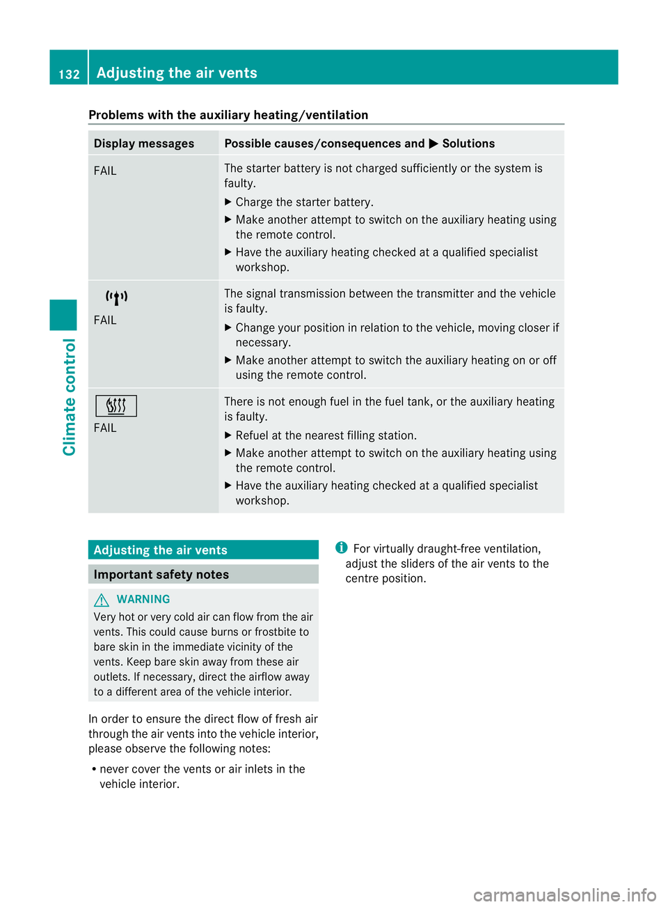
Problems with the auxiliary heating/ventilation
Display messages Possible causes/consequences and
M Solutions
FAIL The starter battery is not charged sufficiently or the system is
faulty.
X
Charge the starter battery.
X Make another attempt to switch on the auxiliary heating using
the remote control.
X Have the auxiliary heating checked at a qualified specialist
workshop. $
FAIL The signal transmission between the transmitter and the vehicle
is faulty.
X
Change your position in relation to the vehicle, moving closer if
necessary.
X Make another attempt to switch the auxiliary heating on or off
using the remote control. ©
FAIL There is not enough fuel in the fuel tank, or the auxiliary heating
is faulty.
X
Refuel at the nearest filling station.
X Make another attempt to switch on the auxiliary heating using
the remote control.
X Have the auxiliary heating checked at a qualified specialist
workshop. Adjusting the air vents
Important safety notes
G
WARNING
Very hot or very cold air can flow from the air
vents. This could cause burns or frostbite to
bare skin in the immediate vicinity of the
vents. Keep bare skin away from these air
outlets. If necessary, direct the airflow away
to a different area of the vehicle interior.
In order to ensure the direct flow of fresh air
through the air vents into the vehicle interior,
please observe the following notes:
R never cover the vents or air inlets in the
vehicle interior. i
For virtually draught-free ventilation,
adjust the sliders of the air vents to the
centre position. 132
Adjusting the air ventsClimate control
Page 142 of 373

Automatic transmission
X
Shift the transmission to position P.
The transmission position display in the
multifunction display shows P.
i You can also start the engine when the
transmission is in position N.
Starting procedure with the key i
To start the engine using the key instead
of KEYLESS-GO ,pull th eStart/Stop button
ou toft he ignition lock.
X To start a petrol engine: turn the key to
position 3in the ignition lock
(Y page 137) and release it as soon as the
engine is running.
X To startad iesel engine: turn the key to
position 2in the ignition lock
(Y page 137).
The % preglow indicator lamp in the
instrumen tcluster lights up.
X When the %preglow indicator lamp
goes out, tur nthe key to position 3
(Y page 137) and release it as soon as the
engine is running.
i You can start the engine without preglow
if the engine is warm.
i Vehicles with automatic transmis-
sion: you can also use the touch-start func-
tion. To do this, turn the key to position 3
(Y page 137) and release it immediately.
The engine then starts automatically.
Using KEYLESS-GO to startt he engineG
WARNING
You rvehicle can be started using a valid KEY-
LESS-GO key. For this reason, children should
never be left unsupervised in the vehicle.
Always take the key with you when leaving the
vehicle, even if you are only leaving it for a
short time.
i The Start/Stop button can be used to
start the vehicle manually without inserting the key into the ignition lock. The key must
be in the vehicle and the Start/Stop button
must be inserted in the ignition lock. This
mode for starting the engine operates inde-
pendently of the ECO start/stop automatic
engine start function.
X Depress the brake pedal and keep it
depressed.
X To star tapetrol engine: press the Start/
Stop button (Y page 137) once.
The engine starts.
X To start adiesel engine: press the Start/
Stop button (Y page 137) once.
Preglow is activated and the engine starts. Pulling away
Manual transmission X
Depress the brake pedal and keep it
depressed.
X Fully depress the clutch pedal.
X Shift to either first gear or reverse gear R.
X Release the parking brake (Y page 159).
X Release the brake pedal.
X Slowly release the clutch pedal and gently
depress the accelerato rpedal.
! Change gear in good time and avoid spin-
ning the wheels. Otherwise, you could dam-
age the vehicle.
i Follow the shift recommendations in the
multifunction display for an economical
driving style (Y page 145).
i The vehicle locks centrally once you have
pulled away. The locking knobs in the doors
drop down.
You can open the doors from the inside at
any time.
You can also deactivate the automatic lock-
ing feature (Y page 226). Driving
139Driving and parking Z
Page 143 of 373

Automatic transmission
i
It is only possible to shif tthe transmission
from position Pto the desired position if
you depress the brake pedal. Only then is
the selector lever lock released.
X Depress the brake pedal and keep it
depressed.
X Shift the transmission to position Dor R.
X Release the parking brake (Y page 159).
X Release the brake pedal.
X Carefully depress the accelerator pedal.
i The vehicle locks centrally once you have
pulled away.T he locking knobs in the doors
drop down.
You can open the doors from the inside at
any time.
You can also deactivate the automatic lock-
ing feature (Y page 226).
i Upshifts take place at higher engine
speeds after a cold start. This helps the
catalytic converter to reach its operating
temperature more quickly.
Hill starta ssist Hill start assist helps you when pulling away
forwards or in reverse on an uphill gradient.
It holds the vehicle for a short time after you
have removed your foot from the brake pedal.
This gives you enough time to move your foot
from the brake pedal to the accelerator pedal
and depress it before the vehicle begins to
roll. G
WARNING
Never leave the vehicle when it is held by hill
start assist. After approximately one second,
hill start assist will no longer brake your vehi-
cle and it could roll away.
X Take your foot off the brake pedal.
i Once you have taken your foot off the
brake pedal, the vehicle is held for around
one second.
X Pull away. Hill start assist will not function if:
R
you are pulling away on a level road or a
downhill gradient.
R on vehicles with automatic transmission,
the transmission is in position N.
R the parking brake is applied.
R ESP ®
is malfunctioning. ECO start/stop function
General notes The ECO start/stop function switches the
engine off automatically if the vehicle stops
moving.
The engine starts automatically when you pull
away again. The ECO start/stop function
thereby helps you to reduce the fuel con-
sumption and emissions of your vehicle.
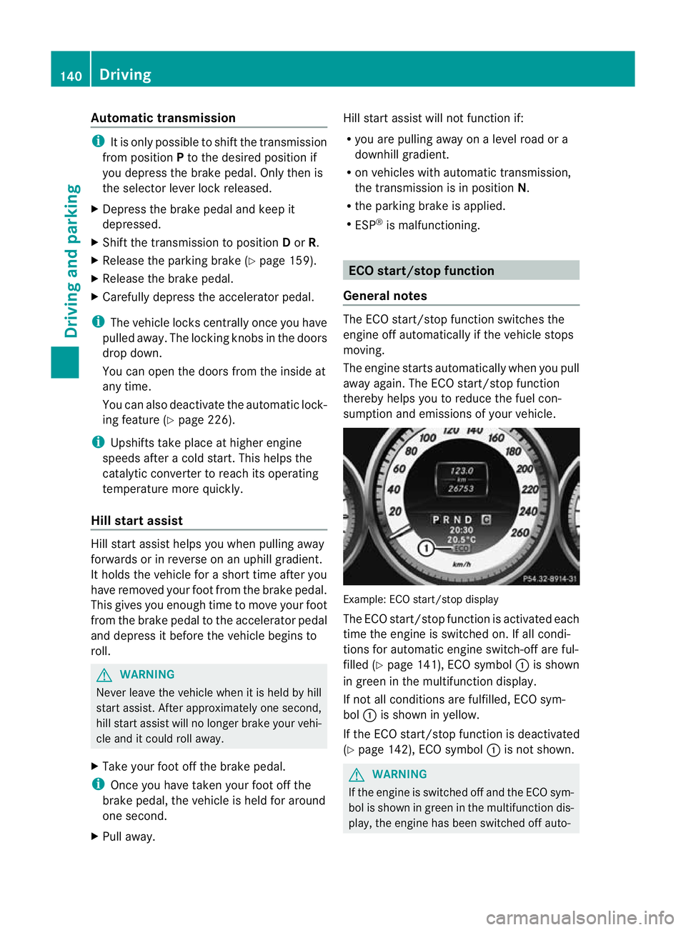
Example: ECO start/stop display
The ECO start/stop function is activated each
time the engine is switched on. If all condi-
tions for automatic engine switch-off are ful-
filled (Y
page 141), ECO symbol :is shown
in green in the multifunction display.
If not all conditions are fulfilled, ECO sym-
bol :is shown in yellow.
If the ECO start/stop function is deactivated
(Y page 142), ECO symbol :is not shown. G
WARNING
If the engine is switched off and the ECO sym-
bol is shown in green in the multifunction dis-
play, the engine has been switched off auto- 140
DrivingDriving and parking