POWER SUPPLY AND GROUND CIRCUITHAC-115
< DTC/CIRCUIT DIAGNOSIS > [AUTOMATIC AIR CONDITIONING]
C
D
E
F
G H
J
K L
M A
B
HAC
N
O P
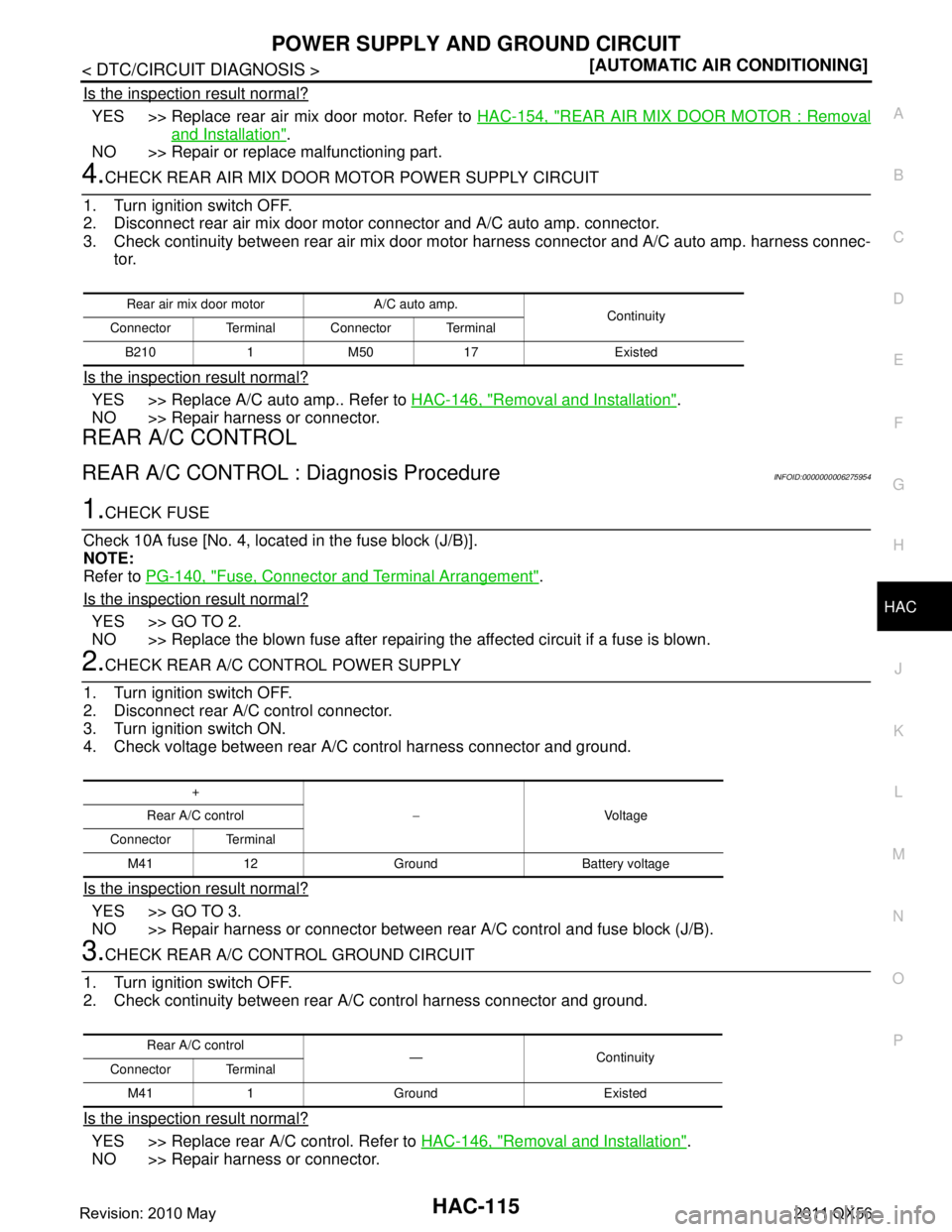
Is the inspection result normal?
YES >> Replace rear air mix door motor. Refer to HAC-154, "REAR AIR MIX DOOR MOTOR : Removal
and Installation".
NO >> Repair or replace malfunctioning part.
4.CHECK REAR AIR MIX DOOR MOTOR POWER SUPPLY CIRCUIT
1. Turn ignition switch OFF.
2. Disconnect rear air mix door motor connector and A/C auto amp. connector.
3. Check continuity between rear air mix door mo tor harness connector and A/C auto amp. harness connec-
tor.
Is the inspection result normal?
YES >> Replace A/C auto amp.. Refer to HAC-146, "Removal and Installation".
NO >> Repair harness or connector.
REAR A/C CONTROL
REAR A/C CONTROL : Diagnosis ProcedureINFOID:0000000006275954
1.CHECK FUSE
Check 10A fuse [No. 4, locat ed in the fuse block (J/B)].
NOTE:
Refer to PG-140, "
Fuse, Connector and Terminal Arrangement".
Is the inspection result normal?
YES >> GO TO 2.
NO >> Replace the blown fuse after repairing the affected circuit if a fuse is blown.
2.CHECK REAR A/C CONTROL POWER SUPPLY
1. Turn ignition switch OFF.
2. Disconnect rear A/C control connector.
3. Turn ignition switch ON.
4. Check voltage between rear A/C control harness connector and ground.
Is the inspection result normal?
YES >> GO TO 3.
NO >> Repair harness or connector between r ear A/C control and fuse block (J/B).
3.CHECK REAR A/C CONTROL GROUND CIRCUIT
1. Turn ignition switch OFF.
2. Check continuity between rear A/ C control harness connector and ground.
Is the inspection result normal?
YES >> Replace rear A/C control. Refer to HAC-146, "Removal and Installation".
NO >> Repair harness or connector.
Rear air mix door motor A/C auto amp. Continuity
Connector Terminal Connector Terminal
B210 1 M50 17 Existed
+ −Voltage
Rear A/C control
Connector Terminal M41 12 Ground Battery voltage
Rear A/C control —Continuity
Connector Terminal
M41 1 Ground Existed
Revision: 2010 May2011 QX56
REAR AUTOMATIC AIR CONDITIONING SYSTEMHAC-135
< SYMPTOM DIAGNOSIS > [AUTOMATIC AIR CONDITIONING]
C
D
E
F
G H
J
K L
M A
B
HAC
N
O P
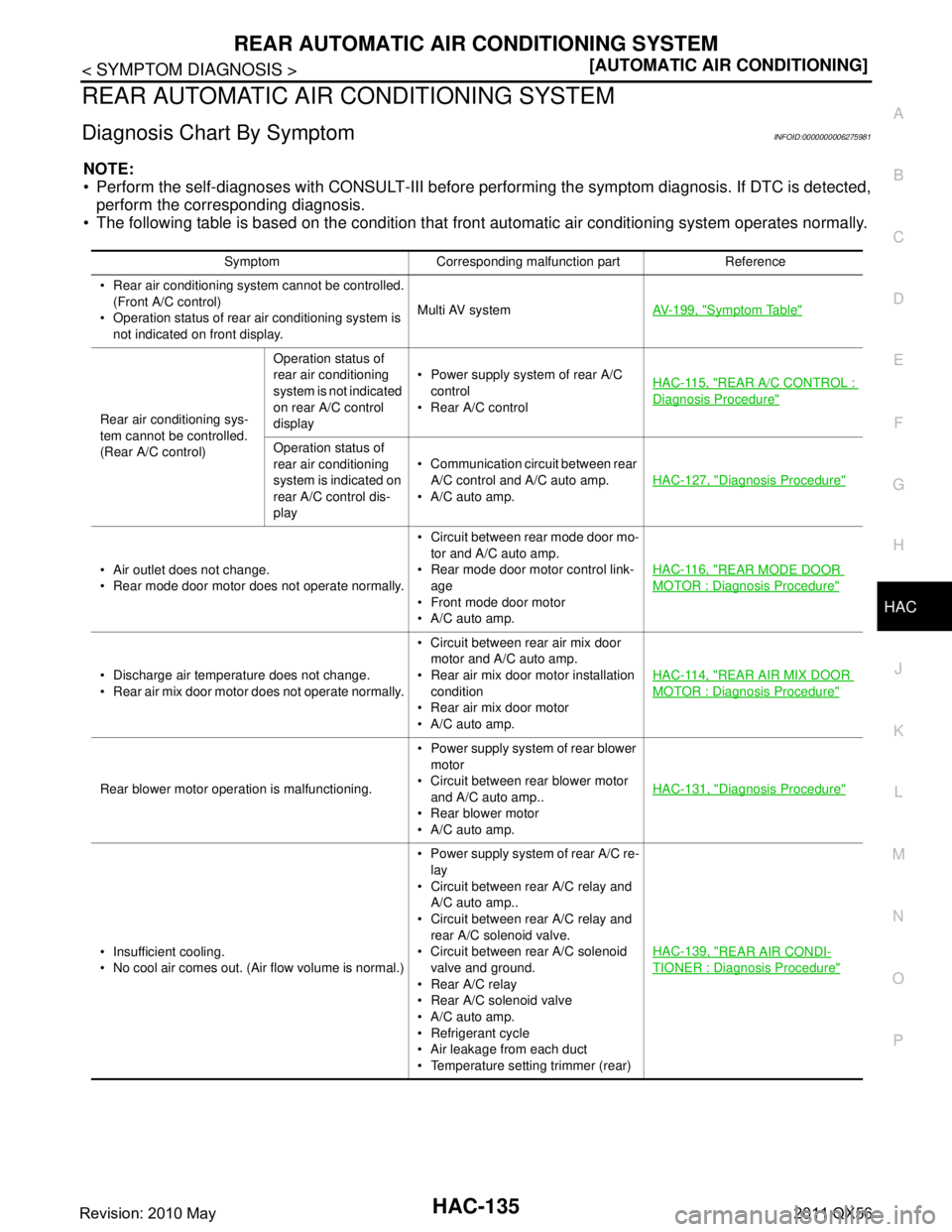
REAR AUTOMATIC AIR CONDITIONING SYSTEM
Diagnosis Chart By SymptomINFOID:0000000006275981
NOTE:
Perform the self-diagnoses with CONSULT-III before performing the symptom diagnosis. If DTC is detected,
perform the corresponding diagnosis.
The following table is based on the condition that fr ont automatic air conditioning system operates normally.
Symptom Corresponding malfunction part Reference
Rear air conditioning system cannot be controlled. (Front A/C control)
Operation status of rear air conditioning system is not indicated on front display. Multi AV system
AV- 1 9 9 , "
Symptom Table"
Rear air conditioning sys-
tem cannot be controlled.
(Rear A/C control)Operation status of
rear air conditioning
system is not indicated
on rear A/C control
display
Power supply system of rear A/C
control
Rear A/C control HAC-115, "
REAR A/C CONTROL :
Diagnosis Procedure"
Operation status of
rear air conditioning
system is indicated on
rear A/C control dis-
play Communication circuit between rear
A/C control and A/C auto amp.
A/C auto amp. HAC-127, "
Diagnosis Procedure"
Air outlet does not change.
Rear mode door motor does not operate normally. Circuit between rear mode door mo-
tor and A/C auto amp.
Rear mode door motor control link- age
Front mode door motor
A/C auto amp. HAC-116, "REAR MODE DOOR
MOTOR : Diagnosis Procedure"
Discharge air temperature does not change.
Rear air mix door motor does not operate normally. Circuit between rear air mix door
motor and A/C auto amp.
Rear air mix door motor installation condition
Rear air mix door motor
A/C auto amp. HAC-114, "REAR AIR MIX DOOR
MOTOR : Diagnosis Procedure"
Rear blower motor operation is malfunctioning.
Power supply system of rear blower
motor
Circuit between rear blower motor
and A/C auto amp..
Rear blower motor
A/C auto amp. HAC-131, "Diagnosis Procedure"
Insufficient cooling.
No cool air comes out. (Air flow volume is normal.) Power supply system of rear A/C re-
lay
Circuit between rear A/C relay and A/C auto amp..
Circuit between rear A/C relay and rear A/C solenoid valve.
Circuit between rear A/C solenoid
valve and ground.
Rear A/C relay
Rear A/C solenoid valve
A/C auto amp.
Refrigerant cycle
Air leakage from each duct
Temperature setti ng trimmer (rear) HAC-139, "REAR AIR CONDI-
TIONER : Diagnosis Procedure"
Revision: 2010 May2011 QX56