2011 INFINITI QX56 HAC-10
[x] Cancel search: HAC-10Page 3116 of 5598
HAC-10
< SYSTEM DESCRIPTION >[AUTOMATIC AIR CONDITIONING]
COMPONENT PARTS
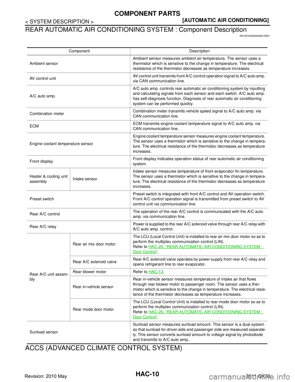
REAR AUTOMATIC AIR CONDITIONING SYSTEM : Component Description
INFOID:0000000006275851
ACCS (ADVANCED CLIMATE CONTROL SYSTEM)
Component Description
Ambient sensor Ambient sensor measures ambient air temperature. The sensor uses a
thermistor which is sensitive to the change in temperature. The electrical
resistance of the thermistor decreases as temperature increases.
AV c o n t r o l u n i t AV control unit transmits front A/C control operation signal to A/C auto amp.
via CAN communication line.
A/C auto amp. A/C auto amp. controls rear automatic air conditioning system by inputting
and calculating signals from each sensor and each switch. A/C auto amp.
has self-diagnosis function. Diagnosis of rear automatic air conditioning
system can be performed quickly.
Combination meter Combination meter transmits vehicle speed signal to A/C auto amp. via
CAN communication line.
ECM ECM transmits engine coolant temperature signal to A/C auto amp. via
CAN communication line.
Engine coolant temperature sensor Engine coolant temperature sensor measures engine coolant temperature.
The sensor uses a thermistor which is sensitive to the change in tempera-
ture. The electrical resistance of the thermistor decreases as temperature
increases.
Front display Front display indicates operation status of rear automatic air conditioning
system.
Heater & cooling unit
assembly Intake sensor Intake sensor measures temperature of front evaporator fin temperature.
The sensor uses a thermistor which is sensitive to the change in tempera-
ture. The electrical resistance of the thermistor decreases as temperature
increases.
Preset switch Preset switch is integrated with front A/C control and AV operation switch.
Front A/C control operation signal is transmitted from preset switch to AV
control unit via communication line.
Rear A/C control The operation of the rear A/C control is communicated with the A/C auto
amp. via communication line.
Rear A/C relay Power is supplied to the rear A/C solenoid valve through rear A/C relay with
A/C auto amp. control.
Rear A/C unit assem-
bly Rear air mix door motor
The LCU (Local Contro
l Unit) is installed to rear air mix door motor so as to
perform the multiplex communication control (LIN).
Refer to HAC-26, "
REAR AUTOMATIC AIR CONDITIONING SYSTEM :
Door Control".
Rear A/C solenoid valve Rear A/C solenoid valve operates by power supply from rear A/C relay and
opens refrigerant line to rear evaporator.
Rear blower motor Refer to HAC-13
.
Rear in-vehicle sensor Rear in-vehicle sensor measures temperature of intake air that flows
through rear blower motor to passenger room. The sensor uses a ther-
mistor which is sensitive to the change in temperature. The electrical resis-
tance of the thermistor decreases as temperature increases.
Rear mode door motor The LCU (Local Control Unit) is installed to rear mode door motor so as to
perform the multiplex communication control (LIN).
Refer to
HAC-26, "
REAR AUTOMATIC AIR CONDITIONING SYSTEM :
Door Control".
Sunload sensor Sunload sensor measures sunload amount. This sensor is a dual system
so that sunload for driver side and passenger side are measured separate-
ly. This sensor converts sunload amount to voltage signal by photodiode
and transmits to A/C auto amp..
Revision: 2010 May2011 QX56
Page 3152 of 5598
HAC-46
< ECU DIAGNOSIS INFORMATION >[AUTOMATIC AIR CONDITIONING]
A/C AUTO AMP.
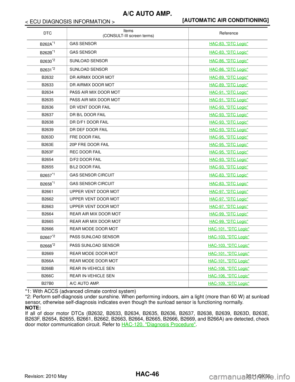
*1: With ACCS (advanced climate control system)
*2: Perform self-diagnosis under sunshine. When performi
ng indoors, aim a light (more than 60 W) at sunload
sensor, otherwise self-diagnosis indicates even though the sunload sensor is functioning normally.
NOTE:
If all of door motor DTCs (B2632, B2633, B2634, B2635, B2636, B2637, B2638, B2639, B263D, B263E,
B263F, B2654, B2655, B2661, B2662, B2663, B2664, B 2665, B2666, B2669, and B266A) are detected, check
door motor communication circuit. Refer to HAC-120, "
Diagnosis Procedure".
B262A*1GAS SENSOR HAC-83, "DTC Logic"
B262B*1GAS SENSORHAC-83, "DTC Logic"
B2630*2SUNLOAD SENSORHAC-86, "DTC Logic"
B2631*2SUNLOAD SENSORHAC-86, "DTC Logic"
B2632 DR AIRMIX DOOR MOT HAC-89, "DTC Logic"
B2633 DR AIRMIX DOOR MOTHAC-89, "DTC Logic"
B2634 PASS AIR MIX DOOR MOTHAC-91, "DTC Logic"
B2635 PASS AIR MIX DOOR MOTHAC-91, "DTC Logic"
B2636 DR VENT DOOR FAILHAC-93, "DTC Logic"
B2637 DR B/L DOOR FAILHAC-93, "DTC Logic"
B2638 DR D/F1 DOOR FAILHAC-93, "DTC Logic"
B2639 DR DEF DOOR FAILHAC-93, "DTC Logic"
B263D FRE DOOR FAIL HAC-95, "DTC Logic"
B263E 20P FRE DOOR FAILHAC-95, "DTC Logic"
B263F REC DOOR FAILHAC-95, "DTC Logic"
B2654 D/F2 DOOR FAILHAC-93, "DTC Logic"
B2655 B/L2 DOOR FAILHAC-93, "DTC Logic"
B2657*1GAS SENSOR CIRCUITHAC-83, "DTC Logic"
B2658*1GAS SENSOR CIRCUITHAC-83, "DTC Logic"
B2661 UPPER VENT DOOR MOT HAC-97, "DTC Logic"
B2662 UPPER VENT DOOR MOTHAC-97, "DTC Logic"
B2663 UPPER VENT DOOR MOTHAC-97, "DTC Logic"
B2664 REAR AIR MIX DOOR MOTHAC-99, "DTC Logic"
B2665 REAR AIR MIX DOOR MOTHAC-99, "DTC Logic"
B2666 REAR MODE DOOR MOTHAC-101, "DTC Logic"
B2667*2PASS SUNLOAD SENSORHAC-103, "DTC Logic"
B2668*2PASS SUNLOAD SENSORHAC-103, "DTC Logic"
B2669 REAR MODE DOOR MOT HAC-101, "DTC Logic"
B266A REAR MODE DOOR MOT HAC-101, "DTC Logic"
B266B REAR IN-VEHICLE SENHAC-106, "DTC Logic"
B266C REAR IN-VEHICLE SEN HAC-106, "DTC Logic"
B27B0 A/C AUTO AMP.HAC-109, "DTC Logic"
DTCItems
(CONSULT-III screen terms) Reference
Revision: 2010 May2011 QX56
Page 3180 of 5598
HAC-74
< DTC/CIRCUIT DIAGNOSIS >[AUTOMATIC AIR CONDITIONING]
B2578, B2579 FRONT IN-VEHICLE SENSOR
B2578, B2579 FRONT IN-VEHICLE SENSOR
DTC LogicINFOID:0000000006275909
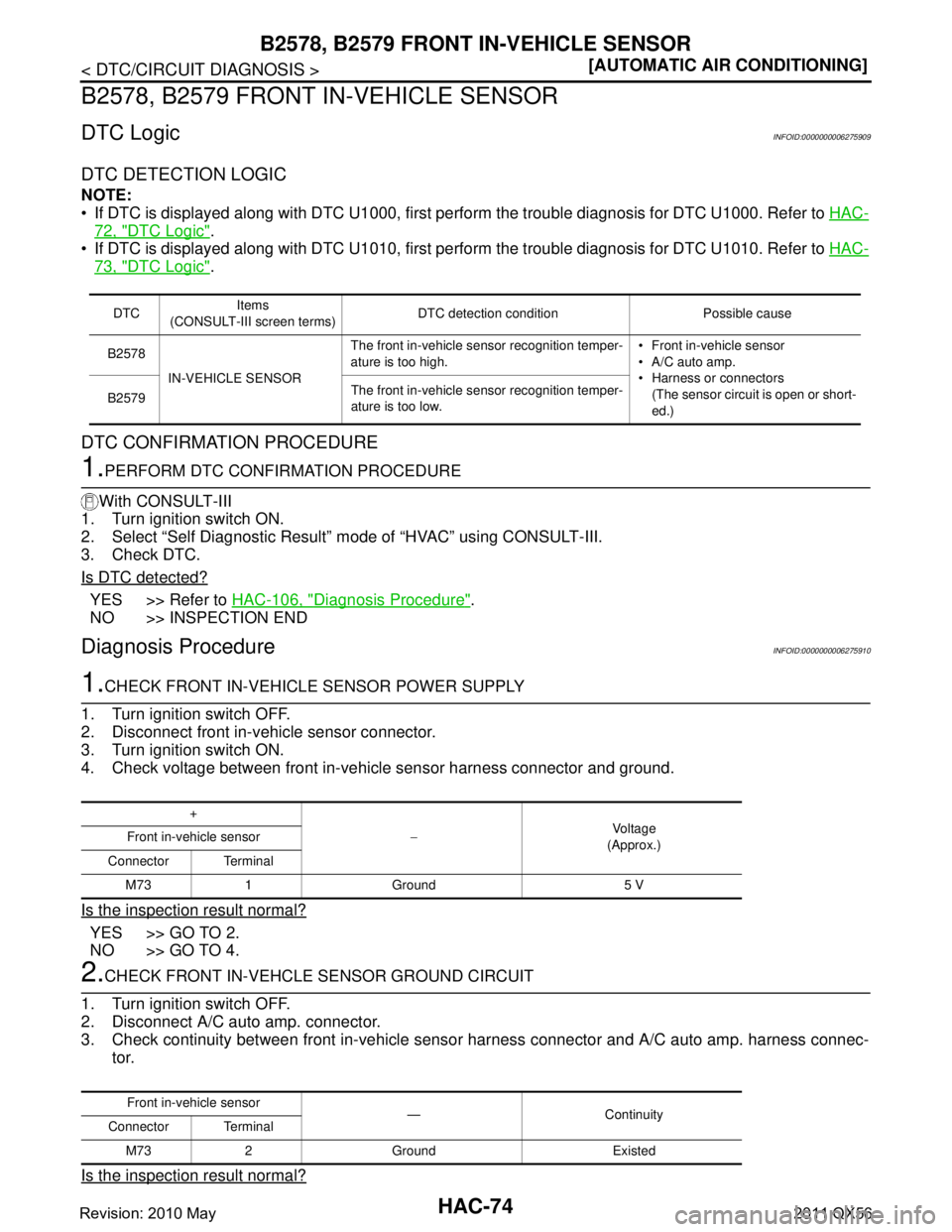
DTC DETECTION LOGIC
NOTE:
If DTC is displayed along with DTC U1000, first perform the trouble diagnosis for DTC U1000. Refer to
HAC-
72, "DTC Logic".
If DTC is displayed along with DTC U1010, first perform the trouble diagnosis for DTC U1010. Refer to HAC-
73, "DTC Logic".
DTC CONFIRMATION PROCEDURE
1.PERFORM DTC CONFIRMATION PROCEDURE
With CONSULT-III
1. Turn ignition switch ON.
2. Select “Self Diagnostic Result” m ode of “HVAC” using CONSULT-III.
3. Check DTC.
Is DTC detected?
YES >> Refer to HAC-106, "Diagnosis Procedure".
NO >> INSPECTION END
Diagnosis ProcedureINFOID:0000000006275910
1.CHECK FRONT IN-VEHICLE SENSOR POWER SUPPLY
1. Turn ignition switch OFF.
2. Disconnect front in-vehicle sensor connector.
3. Turn ignition switch ON.
4. Check voltage between front in-vehicle sensor harness connector and ground.
Is the inspection result normal?
YES >> GO TO 2.
NO >> GO TO 4.
2.CHECK FRONT IN-VEHCLE SENSOR GROUND CIRCUIT
1. Turn ignition switch OFF.
2. Disconnect A/C auto amp. connector.
3. Check continuity between front in-vehicle sensor harness connector and A/C auto amp. harness connec-
tor.
Is the inspection result normal?
DTC Items
(CONSULT-III screen terms) DTC detection condition Possible cause
B2578 IN-VEHICLE SENSOR The front in-vehicle sensor recognition temper-
ature is too high.
Front in-vehicle sensor
A/C auto amp.
Harness or connectors
(The sensor circuit is open or short-
ed.)
B2579
The front in-vehicle sensor recognition temper-
ature is too low.
+
−Voltage
(Approx.)
Front in-vehicle sensor
Connector Terminal M73 1 Ground 5 V
Front in-vehicle sensor —Continuity
Connector Terminal
M73 2 Ground Existed
Revision: 2010 May2011 QX56
Page 3181 of 5598
B2578, B2579 FRONT IN-VEHICLE SENSORHAC-75
< DTC/CIRCUIT DIAGNOSIS > [AUTOMATIC AIR CONDITIONING]
C
D
E
F
G H
J
K L
M A
B
HAC
N
O P
YES >> GO TO 3.
NO >> Repair harness or connector.
3.CHECK FRONT IN-VEHICLE SENSOR
Check front in-vehicle sensor. Refer to HAC-107, "
Component Inspection".
Is the inspection result normal?
YES >> Replace A/C auto amp.. Refer to HAC-146, "Removal and Installation".
NO >> Replace front in-vehicle sensor. Refer to HAC-148, "
FRONT A/C UNIT ASSEMBLY : Removal
and Installation".
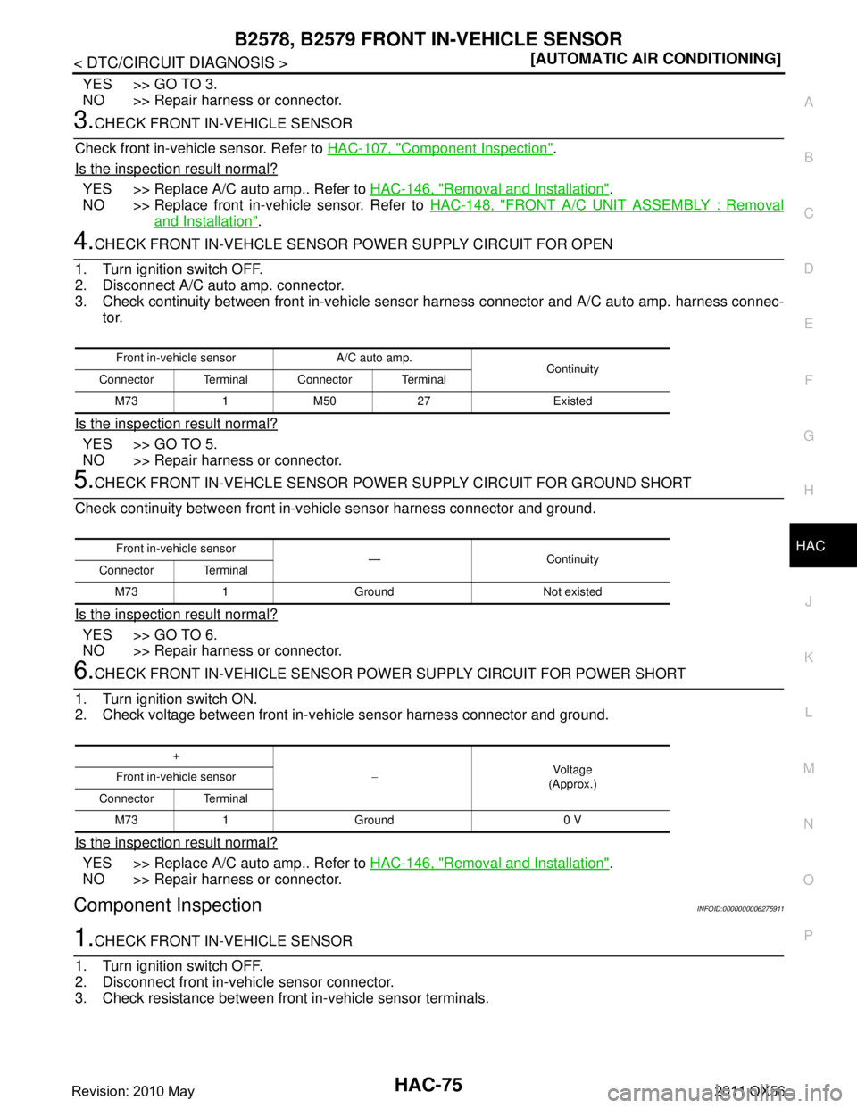
4.CHECK FRONT IN-VEHCLE SENSOR POWER SUPPLY CIRCUIT FOR OPEN
1. Turn ignition switch OFF.
2. Disconnect A/C auto amp. connector.
3. Check continuity between front in-vehicle sens or harness connector and A/C auto amp. harness connec-
tor.
Is the inspection result normal?
YES >> GO TO 5.
NO >> Repair harness or connector.
5.CHECK FRONT IN-VEHCLE SENSOR POWER SUPPLY CIRCUIT FOR GROUND SHORT
Check continuity between front in-vehicle sensor harness connector and ground.
Is the inspection result normal?
YES >> GO TO 6.
NO >> Repair harness or connector.
6.CHECK FRONT IN-VEHICLE SENSOR PO WER SUPPLY CIRCUIT FOR POWER SHORT
1. Turn ignition switch ON.
2. Check voltage between front in-vehicle sensor harness connector and ground.
Is the inspection result normal?
YES >> Replace A/C auto amp.. Refer to HAC-146, "Removal and Installation".
NO >> Repair harness or connector.
Component InspectionINFOID:0000000006275911
1.CHECK FRONT IN-VEHICLE SENSOR
1. Turn ignition switch OFF.
2. Disconnect front in-vehicle sensor connector.
3. Check resistance between front in-vehicle sensor terminals.
Front in-vehicle sensor A/C auto amp. Continuity
Connector Terminal Connector Terminal
M73 1 M50 27 Existed
Front in-vehicle sensor —Continuity
Connector Terminal
M73 1 Ground Not existed
+ −Vol tag e
(Approx.)
Front in-vehicle sensor
Connector Terminal M73 1 Ground 0 V
Revision: 2010 May2011 QX56
Page 3192 of 5598
HAC-86
< DTC/CIRCUIT DIAGNOSIS >[AUTOMATIC AIR CONDITIONING]
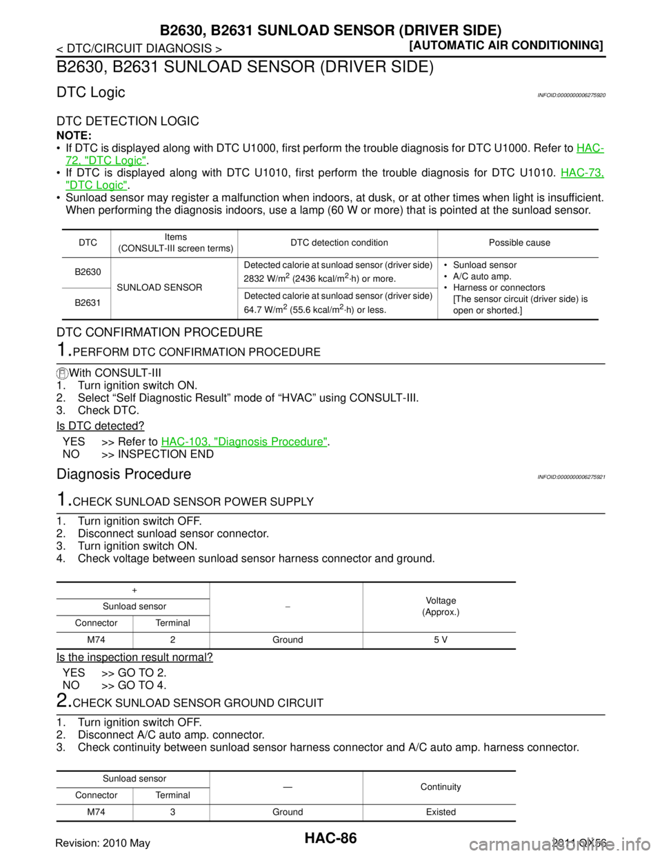
B2630, B2631 SUNLOAD
SENSOR (DRIVER SIDE)
B2630, B2631 SUNLOAD SEN SOR (DRIVER SIDE)
DTC LogicINFOID:0000000006275920
DTC DETECTION LOGIC
NOTE:
If DTC is displayed along with DTC U1000, first perform the trouble diagnosis for DTC U1000. Refer to HAC-
72, "DTC Logic".
If DTC is displayed along with DTC U1010, fi rst perform the trouble diagnosis for DTC U1010. HAC-73,
"DTC Logic".
Sunload sensor may register a malfunction when indoors, at dusk, or at other times when light is insufficient.
When performing the diagnosis indoors, use a lamp (60 W or more) that is pointed at the sunload sensor.
DTC CONFIRMATION PROCEDURE
1.PERFORM DTC CONFIRMATION PROCEDURE
With CONSULT-III
1. Turn ignition switch ON.
2. Select “Self Diagnostic Result” m ode of “HVAC” using CONSULT-III.
3. Check DTC.
Is DTC detected?
YES >> Refer to HAC-103, "Diagnosis Procedure".
NO >> INSPECTION END
Diagnosis ProcedureINFOID:0000000006275921
1.CHECK SUNLOAD SENSOR POWER SUPPLY
1. Turn ignition switch OFF.
2. Disconnect sunload sensor connector.
3. Turn ignition switch ON.
4. Check voltage between sunload sensor harness connector and ground.
Is the inspection result normal?
YES >> GO TO 2.
NO >> GO TO 4.
2.CHECK SUNLOAD SENSOR GROUND CIRCUIT
1. Turn ignition switch OFF.
2. Disconnect A/C auto amp. connector.
3. Check continuity between sunload sensor harne ss connector and A/C auto amp. harness connector.
DTCItems
(CONSULT-III screen terms) DTC detection condition Possible cause
B2630 SUNLOAD SENSOR Detected calorie at sunload sensor (driver side)
2832 W/m
2 (2436 kcal/m2·h) or more.
Sunload sensor
A/C auto amp.
Harness or connectors
[The sensor circui t (driver side) is
open or shorted.]
B2631
Detected calorie at sunload sensor (driver side)
64.7 W/m
2 (55.6 kcal/m2·h) or less.
+
−Voltage
(Approx.)
Sunload sensor
Connector Terminal M74 2 Ground 5 V
Sunload sensor —Continuity
Connector Terminal
M74 3 Ground Existed
Revision: 2010 May2011 QX56
Page 3193 of 5598
B2630, B2631 SUNLOAD SENSOR (DRIVER SIDE)HAC-87
< DTC/CIRCUIT DIAGNOSIS > [AUTOMATIC AIR CONDITIONING]
C
D
E
F
G H
J
K L
M A
B
HAC
N
O P
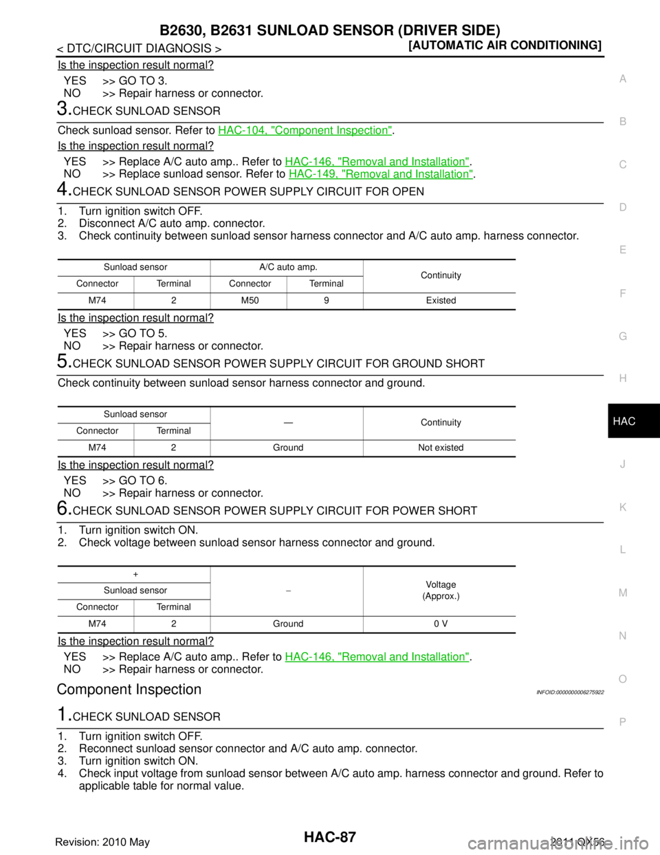
Is the inspection result normal?
YES >> GO TO 3.
NO >> Repair harness or connector.
3.CHECK SUNLOAD SENSOR
Check sunload sensor. Refer to HAC-104, "
Component Inspection".
Is the inspection result normal?
YES >> Replace A/C auto amp.. Refer to HAC-146, "Removal and Installation".
NO >> Replace sunload sensor. Refer to HAC-149, "
Removal and Installation".
4.CHECK SUNLOAD SENSOR POWER SUPPLY CIRCUIT FOR OPEN
1. Turn ignition switch OFF.
2. Disconnect A/C auto amp. connector.
3. Check continuity between sunload sensor harnes s connector and A/C auto amp. harness connector.
Is the inspection result normal?
YES >> GO TO 5.
NO >> Repair harness or connector.
5.CHECK SUNLOAD SENSOR POWER SU PPLY CIRCUIT FOR GROUND SHORT
Check continuity between sunload sensor harness connector and ground.
Is the inspection result normal?
YES >> GO TO 6.
NO >> Repair harness or connector.
6.CHECK SUNLOAD SENSOR POWER SU PPLY CIRCUIT FOR POWER SHORT
1. Turn ignition switch ON.
2. Check voltage between sunload sensor harness connector and ground.
Is the inspection result normal?
YES >> Replace A/C auto amp.. Refer to HAC-146, "Removal and Installation".
NO >> Repair harness or connector.
Component InspectionINFOID:0000000006275922
1.CHECK SUNLOAD SENSOR
1. Turn ignition switch OFF.
2. Reconnect sunload sensor connector and A/C auto amp. connector.
3. Turn ignition switch ON.
4. Check input voltage from sunload sensor between A/C auto amp. harness connector and ground. Refer to
applicable table for normal value.
Sunload sensor A/C auto amp. Continuity
Connector Terminal Connector Terminal
M74 2 M50 9 Existed
Sunload sensor —Continuity
Connector Terminal
M74 2 Ground Not existed
+ −Vol tag e
(Approx.)
Sunload sensor
Connector Terminal M74 2 Ground 0 V
Revision: 2010 May2011 QX56
Page 3206 of 5598
HAC-100
< DTC/CIRCUIT DIAGNOSIS >[AUTOMATIC AIR CONDITIONING]
B2664, B2665 REAR AI
R MIX DOOR MOTOR
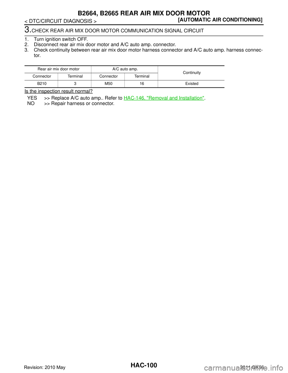
3.CHECK REAR AIR MIX DOOR MOTOR COMMUNICATION SIGNAL CIRCUIT
1. Turn ignition switch OFF.
2. Disconnect rear air mix door mo tor and A/C auto amp. connector.
3. Check continuity between rear air mix door mo tor harness connector and A/C auto amp. harness connec-
tor.
Is the inspection result normal?
YES >> Replace A/C auto amp.. Refer to HAC-146, "Removal and Installation".
NO >> Repair harness or connector.
Rear air mix door motor A/C auto amp. Continuity
Connector Terminal Connector Terminal
B210 3 M50 16 Existed
Revision: 2010 May2011 QX56
Page 3207 of 5598
B2666, B2669, B266A REAR MODE DOOR MOTOR
HAC-101
< DTC/CIRCUIT DIAGNOSIS > [AUTOMATIC AIR CONDITIONING]
C
D
E
F
G H
J
K L
M A
B
HAC
N
O P
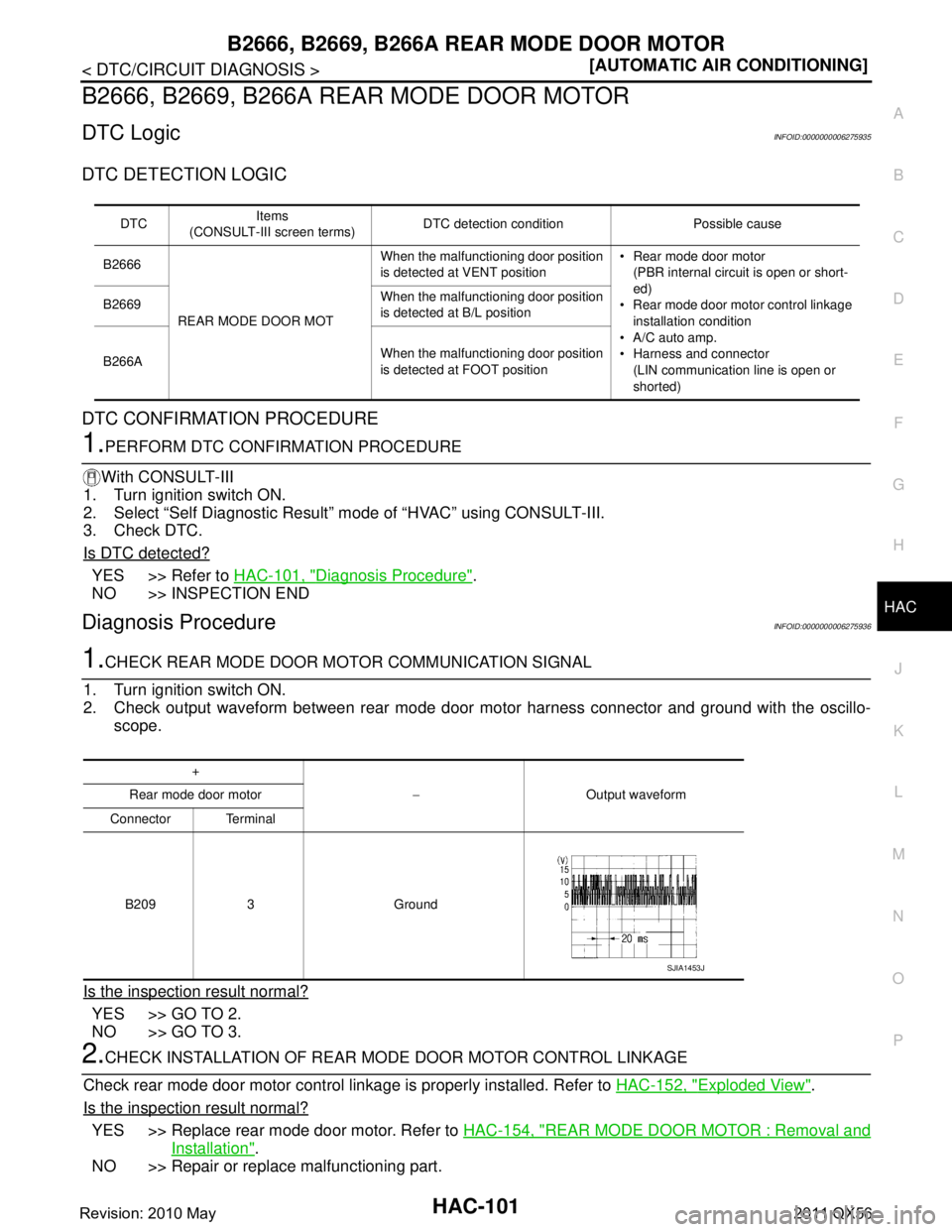
B2666, B2669, B266A REAR MODE DOOR MOTOR
DTC LogicINFOID:0000000006275935
DTC DETECTION LOGIC
DTC CONFIRMATION PROCEDURE
1.PERFORM DTC CONFIRMATION PROCEDURE
With CONSULT-III
1. Turn ignition switch ON.
2. Select “Self Diagnostic Result” m ode of “HVAC” using CONSULT-III.
3. Check DTC.
Is DTC detected?
YES >> Refer to HAC-101, "Diagnosis Procedure".
NO >> INSPECTION END
Diagnosis ProcedureINFOID:0000000006275936
1.CHECK REAR MODE DOOR MO TOR COMMUNICATION SIGNAL
1. Turn ignition switch ON.
2. Check output waveform between rear mode door motor harness connector and ground with the oscillo-
scope.
Is the inspection result normal?
YES >> GO TO 2.
NO >> GO TO 3.
2.CHECK INSTALLATION OF REAR MO DE DOOR MOTOR CONTROL LINKAGE
Check rear mode door motor control linkage is properly installed. Refer to HAC-152, "
Exploded View".
Is the inspection result normal?
YES >> Replace rear mode door motor. Refer to HAC-154, "REAR MODE DOOR MOTOR : Removal and
Installation".
NO >> Repair or replace malfunctioning part.
DTC Items
(CONSULT-III screen terms) DTC detection condition Possible cause
B2666
REAR MODE DOOR MOT When the malfunctioning door position
is detected at VENT position
Rear mode door motor
(PBR internal circuit is open or short-
ed)
Rear mode door motor control linkage
installation condition
A/C auto amp.
Harness and connector (LIN communication line is open or
shorted)
B2669
When the malfunctioning door position
is detected at B/L position
B266A When the malfunctioning door position
is detected at FOOT position
+
−Output waveform
Rear mode door motor
Connector Terminal
B209 3 Ground
SJIA1453J
Revision: 2010 May2011 QX56