2011 INFINITI QX56 cooling fan
[x] Cancel search: cooling fanPage 3434 of 5598

LAN-14
< SYSTEM DESCRIPTION >[CAN FUNDAMENTAL]
TROUBLE DIAGNOSIS
Example: CAN-H, CAN-L Harness Short Circuit
CAN Diagnosis with CONSULT-IIIINFOID:0000000006220519
CAN diagnosis on CONSULT-III extracts the root
cause by receiving the following information.
Response to the system call
Control unit diagnosis information
Self-diagnosis
CAN diagnostic support monitor
SKIB8741E
Unit name Major symptom
ECM Engine torque limiting is affected, and shift harshness increases.
Engine speed drops.
BCM Reverse warning chime does not sound.
The front wiper moves under continuous operation mode even though the front
wiper switch being in the intermittent position.
The room lamp does not turn ON.
The engine does not start (if an error or malfunction occurs while turning the igni- tion switch OFF.)
The steering lock does not release (if an error or malfunction occurs while turning the ignition switch OFF.)
EPS control unit The steeri ng effort increases.
Combination meter The tachometer and the speedometer do not move.
Warning lamps turn ON.
Indicator lamps do not turn ON.
ABS actuator and electric unit (control unit) Normal operation.
TCM No impact on operation.
IPDM E/R When the ignition switch is ON,
The headlamps (Lo) turn ON.
The cooling fan continues to rotate.
Revision: 2010 May2011 QX56
Page 3448 of 5598

LAN-28
< SYSTEM DESCRIPTION >[CAN]
SYSTEM
Check CAN system type from the vehicle shape and equipment.
CAN COMMUNICATION SYSTEM : CA
N Communication Signal ChartINFOID:0000000006220533
Refer to LAN-17, "How to Use CAN Communication Signal Chart" for how to use CAN communication signal
chart.
T: Transmit R: Receive
1. ICC sensor
A. With ICC system
JSMIA0342ZZ
Signal nameECM
4WD
ABS
TCM
A-BAG
AFSAV
BCM
CGW
HVAC
M&A
STRG
TPMS
IPDM-E ADP
PSB
E-SUS ICC
PWBD
A/C compressor request
signal TR
Accelerator pedal position
signal TRRR
R
ASCD OD cancel request
signal TR
ASCD operation signal T R
ASCD status signal T R
Closed throttle position sig-
nal TR
R
Cooling fan speed request
signal TR
Engine and A/T integrated
control signal TR
RT
Engine coolant temperature
signal TRR
Engine restart request sig-
nal TRR
TR
Engine speed signal T R R R R R R R
Engine status signal T R R R
Engine torque signal T R
Fuel consumption monitor
signal TRR
ICC brake switch signal T R
ICC prohibition signal T R
ICC steering switch signal T R
Malfunctioning indicator
lamp signal TR
N idle instruction signal TR
RT
Revision: 2010 May2011 QX56
Page 3666 of 5598
OIL PUMPLU-13
< REMOVAL AND INSTALLATION >
C
DE
F
G H
I
J
K L
M A
LU
NP
O
OIL PUMP
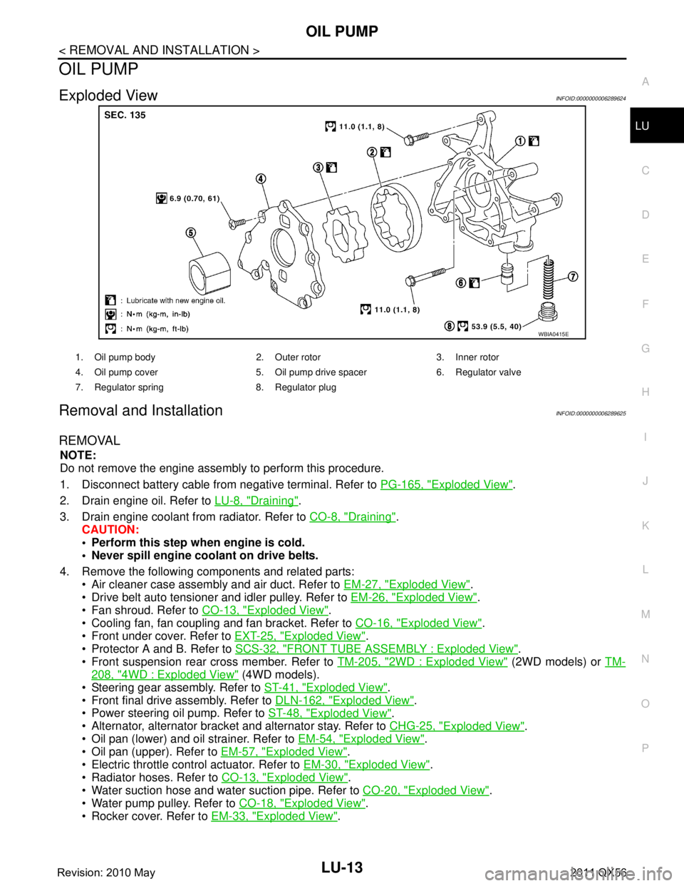
Exploded ViewINFOID:0000000006289624
Removal and InstallationINFOID:0000000006289625
REMOVAL
NOTE:
Do not remove the engine assembly to perform this procedure.
1. Disconnect battery cable from
negative terminal. Refer to PG-165, "
Exploded View".
2. Drain engine oil. Refer to LU-8, "
Draining".
3. Drain engine coolant from radiator. Refer to CO-8, "
Draining".
CAUTION:
Perform this step when engine is cold.
Never spill engine coolant on drive belts.
4. Remove the following components and related parts: Air cleaner case assembly and air duct. Refer to EM-27, "
Exploded View".
Drive belt auto tensioner and idler pulley. Refer to EM-26, "
Exploded View".
Fan shroud. Refer to CO-13, "
Exploded View".
Cooling fan, fan coupling and fan bracket. Refer to CO-16, "
Exploded View".
Front under cover. Refer to EXT-25, "
Exploded View".
Protector A and B. Refer to SCS-32, "
FRONT TUBE ASSEMBLY : Exploded View".
Front suspension rear cross member. Refer to TM-205, "
2WD : Exploded View" (2WD models) or TM-
208, "4WD : Exploded View" (4WD models).
Steering gear assembly. Refer to ST-41, "
Exploded View".
Front final drive assembly. Refer to DLN-162, "
Exploded View".
Power steering oil pump. Refer to ST-48, "
Exploded View".
Alternator, alternator bracket and alternator stay. Refer to CHG-25, "
Exploded View".
Oil pan (lower) and oil strainer. Refer to EM-54, "
Exploded View".
Oil pan (upper). Refer to EM-57, "
Exploded View".
Electric throttle control actuator. Refer to EM-30, "
Exploded View".
Radiator hoses. Refer to CO-13, "
Exploded View".
Water suction hose and water suction pipe. Refer to CO-20, "
Exploded View".
Water pump pulley. Refer to CO-18, "
Exploded View".
Rocker cover. Refer to EM-33, "
Exploded View".
WBIA0415E
1. Oil pump body 2. Outer rotor 3. Inner rotor
4. Oil pump cover 5. Oil pump drive spacer 6. Regulator valve
7. Regulator spring 8. Regulator plug
Revision: 2010 May2011 QX56
Page 3682 of 5598
MA-12
< PERIODIC MAINTENANCE >
ENGINE MAINTENANCE
ENGINE MAINTENANCE
DRIVE BELTS
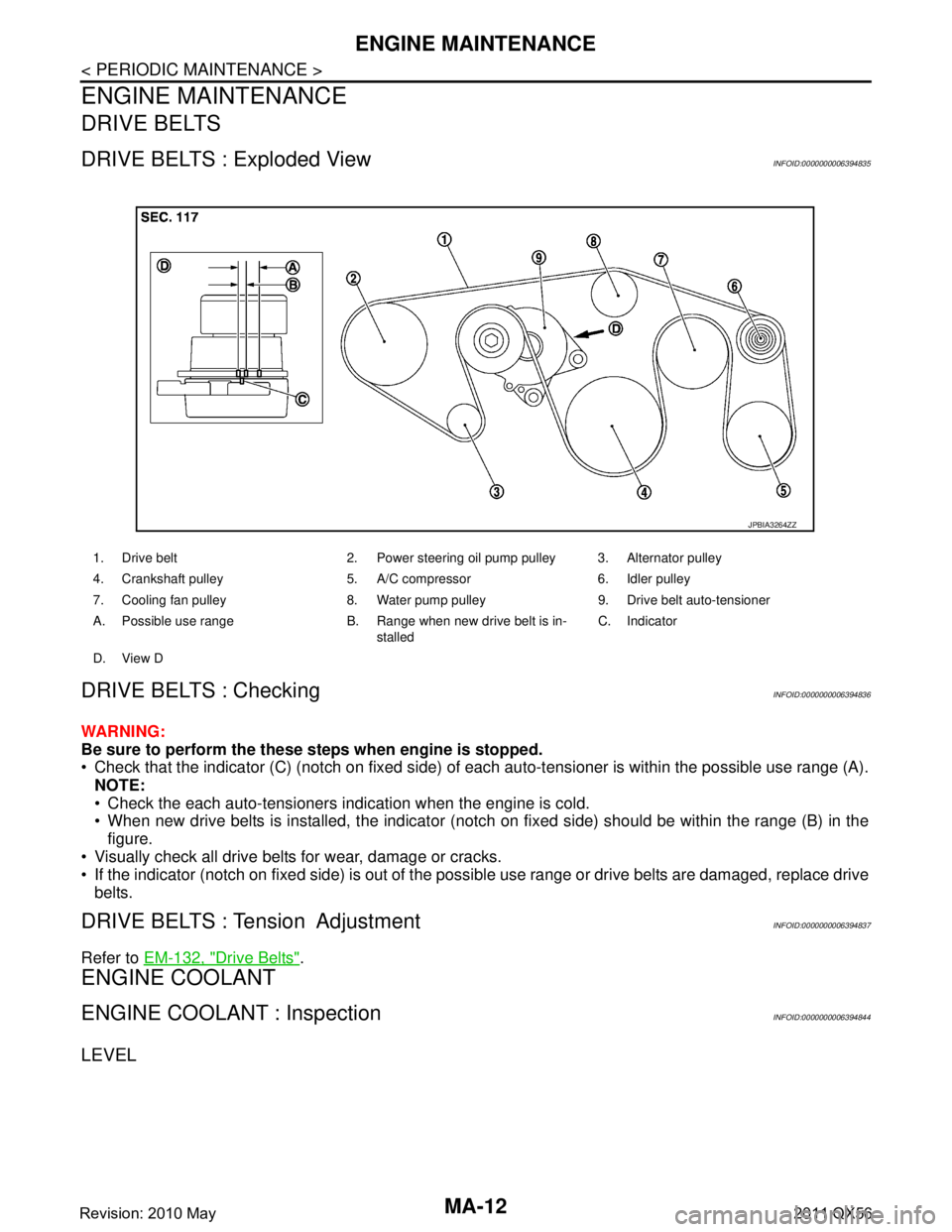
DRIVE BELTS : Exploded ViewINFOID:0000000006394835
DRIVE BELTS : CheckingINFOID:0000000006394836
WARNING:
Be sure to perform the these steps when engine is stopped.
Check that the indicator (C) (notch on fixed side) of each auto-tensioner is within the possible use range (A).
NOTE:
Check the each auto-tensioners indication when the engine is cold.
When new drive belts is installed, the indicator (notch on fixed side) should be within the range (B) in the\
figure.
Visually check all drive belts for wear, damage or cracks.
If the indicator (notch on fixed side) is out of the possible use range or drive belts are damaged, replace drive
belts.
DRIVE BELTS : Tension AdjustmentINFOID:0000000006394837
Refer to EM-132, "Drive Belts".
ENGINE COOLANT
ENGINE COOLANT : InspectionINFOID:0000000006394844
LEVEL
1. Drive belt 2. Power steering oil pump pulley 3. Alternator pulley
4. Crankshaft pulley 5. A/C compressor 6. Idler pulley
7. Cooling fan pulley 8. Water pump pulley 9. Drive belt auto-tensioner
A. Possible use range B. Range when new drive belt is in-
stalledC. Indicator
D. View D
JPBIA3264ZZ
Revision: 2010 May2011 QX56
Page 3686 of 5598
MA-16
< PERIODIC MAINTENANCE >
ENGINE MAINTENANCE
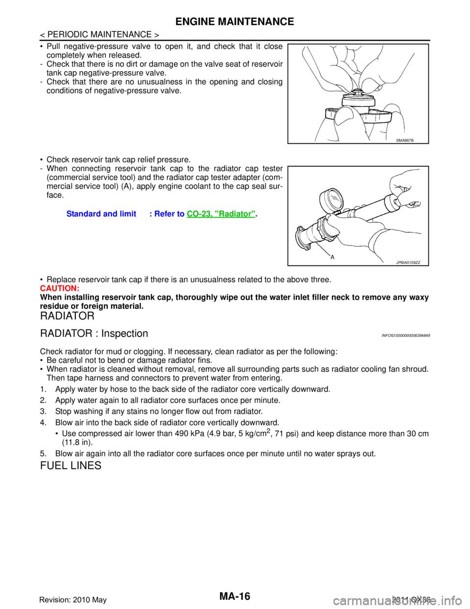
Pull negative-pressure valve to open it, and check that it closecompletely when released.
- Check that there is no dirt or damage on the valve seat of reservoir
tank cap negative-pressure valve.
- Check that there are no unusualness in the opening and closing conditions of negative-pressure valve.
Check reservoir tank cap relief pressure.
- When connecting reservoir tank cap to the radiator cap tester (commercial service tool) and the radiator cap tester adapter (com-
mercial service tool) (A), apply engine coolant to the cap seal sur-
face.
Replace reservoir tank cap if there is an unusualness related to the above three.
CAUTION:
When installing reservoir tank cap, thoroughly wipe out the water inlet filler neck to remove any waxy
residue or foreign material.
RADIATOR
RADIATOR : InspectionINFOID:0000000006394849
Check radiator for mud or clogging. If nec essary, clean radiator as per the following:
Be careful not to bend or damage radiator fins.
When radiator is cleaned without removal, remove all surrounding parts such as radiator cooling fan shroud. Then tape harness and connectors to prevent water from entering.
1. Apply water by hose to the back side of the radiator core vertically downward.
2. Apply water again to all radiator core surfaces once per minute.
3. Stop washing if any stains no longer flow out from radiator.
4. Blow air into the back side of radiator core vertically downward. Use compressed air lower than 490 kPa (4.9 bar, 5 kg/cm
2, 71 psi) and keep distance more than 30 cm
(11.8 in).
5. Blow air again into all the radiator core su rfaces once per minute until no water sprays out.
FUEL LINES
SMA967B
Standard and limit : Refer to CO-23, "Radiator".
JPBIA0109ZZ
Revision: 2010 May2011 QX56
Page 3847 of 5598

PCS-6
< SYSTEM DESCRIPTION >[IPDM E/R]
SYSTEM
NOTE:
BCM controls the starter relay.
RELAY CONTROL SYSTEM : Fail-SafeINFOID:0000000006220163
CAN COMMUNICATION CONTROL
When CAN communication with ECM and BCM is impossible,
IPDM E/R performs fail-safe control. After CAN
communication recovers normally, it also returns to normal control.
If No CAN Communication Is Available With ECM
If No CAN Communication Is Available With BCM
Control relay Input/output Transmi t unit Control part Reference page
Headlamp low relay
Headlamp high relay Low beam request signal
High beam request signal
BCM (CAN)
Headlamp (LO)
Headlamp (HI) EXL-10
Front fog lamp relay Front fog light request signal BCM (CAN) Front fog lamp
EXL-20
Tail lamp relay Position light request signal BCM (CAN) Parking lamp
License plate
lamp
Tail lamp
Side marker lamp EXL-18
Illuminations
INL-6
Front wiper relay
Front wiper high relayFront wiper request signal BCM (CAN)
Front wiper motorWW-7Front wiper stop position sig-
nal Front wiper motor
Rear window defogger
relay Rear window defogger control
signal
BCM (CAN)
Rear window defog-
ger
DEF-6
Horn relay
Theft warning horn
relay Theft warning horn request
signal
Horn reminder signal BCM (CAN)
Horn (high)
Horn (low) SEC-17
Starter relayNOTE
Starter control relayStarter control rela
y signal BCM (CAN)
Starter motorSEC-10
,
SEC-10Steering lock unit condition
signal Steering lock unit
Starter relay control signal TCM
Steering lock relay Steering lock relay signal BCM (CAN)
Steering lock unitSEC-10
Steering lock unit condition
signal Steering lock unit
A/T shift selector (detention
switch) signal A/T shift selector
(detention switch)
A/C relay A/C compressor request sig-
nal ECM (CAN)
A/C compressor
(Magnet clutch) HAC-17
Headlamp washer relay
Headlamp washer request
signal BCM (CAN)Headlamp washer
pump WW-13
Ignition relay
Ignition relay-2
Ignition relay-3Ignition switch ON signal BCM (CAN)
Each control unit,
sensor, actuator and
relay (ignition power
supply)PCS-29Vehicle speed signal
Combination meter
(CAN)
Push-button ignition switch
signal Push-button ignition
switch
Control part Fail-safe operation
Cooling fan Transmits the pulse duty signal (PWM signal) 100% when the ignition switch is turned ON.
Transmits the pulse duty signal (PWM signal) 0% when the ignition switch is turned OFF.
A/C compressor A/C relay OFF
Alternator Transmits the power generation command signal (PWM signal) 0%
Revision: 2010 May2011 QX56
Page 3849 of 5598

PCS-8
< SYSTEM DESCRIPTION >[IPDM E/R]
SYSTEM
POWER CONTROL SYSTEM : System Diagram
INFOID:0000000006220164
POWER CONTROL SYSTEM : System DescriptionINFOID:0000000006220165
COOLING FAN CONTROL
IPDM E/R outputs cooling fan control signal (PWM signal ) to the electrically-controlled cooling fan coupling
according to the status of the cooling fan speed request signal received from ECM via CAN communication.
Refer to EC-41, "
COOLING FAN CONTROL : System Diagram".
ALTERNATOR CONTROL
IPDM E/R outputs power generation command signal (PWM signal ) to the alternator according to the status of
the power generation command value signal received from ECM via CAN communication. Refer to CHG-7,
"POWER GENERATION VOLTAGE VARIABLE CONTROL SYSTEM : System Diagram".
SIGNAL BUFFER SYSTEM
SIGNAL BUFFER SYSTEM : System DiagramINFOID:0000000006220166
SIGNAL BUFFER SYSTEM : System DescriptionINFOID:0000000006220167
IPDM E/R reads the status of the oil pressure switch and transmits the oil pressure switch signal to BCM via
CAN communication. Refer to MWI-15, "
OIL PRESSURE WARNING LAMP : System Diagram".
IPDM E/R reads the status of the hood switch and tr ansmits the hood switch signal to BCM via CAN commu-
nication. Refer to SEC-17, "
VEHICLE SECURITY SYSTEM : System Diagram".
IPDM E/R receives the rear window defogger control signal from BCM via CAN communication and trans- mits it to ECM and AV control unit via CAN communication. Refer to DEF-6, "
System Diagram".
POWER CONSUMPTION CONTROL SYSTEM
JMMIA0491GB
JPMIA0952GB
Revision: 2010 May2011 QX56
Page 3853 of 5598

PCS-12
< SYSTEM DESCRIPTION >[IPDM E/R]
DIAGNOSIS SYSTEM (IPDM E/R)
CONSULT-III Function (IPDM E/R)
INFOID:0000000006220171
APPLICATION ITEM
CONSULT-III performs the following functions via CAN communication with IPDM E/R.
SELF DIAGNOSTIC RESULT
Refer to PCS-22, "DTCIndex".
DATA MONITOR
Monitor item
Oil pressure warning lamp does not operate Perform auto active test.
Does the oil pressure warning
lamp blink?YES
Harness or connector be-
tween IPDM E/R and oil
pressure switch
Oil pressure switch
IPDM E/R
NO CAN communication signal
between IPDM E/R and
BCM
CAN communication signal
between BCM and combi-
nation meter
Combination meter
Symptom Inspection contents Possible cause
Diagnosis mode Description
Ecu Identification Allows confirmation of IPDM E/R part number.
Self Diagnostic Result Displays the diagnosis results judged by IPDM E/R.
Data Monitor Displays the real-time input/output data from IPDM E/R input/output data.
Active Test IPDM E/R can provide a drive signal to electronic components to check their operations.
CAN Diag Support Monitor The results of transmit/receive diagnosis of CAN communication can be read.
Monitor Item [Unit] MAIN SIG-
NALS Description
RAD FAN REQ
[1/2/3/4] ×Displays the value of the cooling fan speed request signal received from ECM via
CAN communication.
AC COMP REQ
[Off/On] ×Displays the status of the A/C compressor request signal received from ECM via
CAN communication.
TA I L & C L R R E Q
[Off/On] ×
Displays the status of the position light request signal received from BCM via CAN
communication.
HL LO REQ
[Off/On] ×Displays the status of the low beam request signal received from BCM via CAN
communication.
HL HI REQ
[Off/On] ×Displays the status of the high beam request signal received from BCM via CAN
communication.
FR FOG REQ
[Off/On] ×Displays the status of the front fog light request signal received from BCM via
CAN communication.
FR WIP REQ
[Stop/1LOW/Low/Hi] ×
Displays the status of the front wiper request signal received from BCM via CAN
communication.
WIP AUTO STOP
[STOP P/ACT P] ×
Displays the status of the front wiper auto stop signal judged by IPDM E/R.
WIP PROT
[Off/BLOCK] ×
Displays the status of the front wiper fail-safe operation judged by IPDM E/R.
IGN RLY1 -REQ
[Off/On] Displays the status of the ignition switch ON signal received from BCM via CAN
communication.
IGN RLY
[Off/On] ×
Displays the status of the ignition relay judged by IPDM E/R.
Revision: 2010 May2011 QX56