2011 INFINITI QX56 tires
[x] Cancel search: tiresPage 4380 of 5598
![INFINITI QX56 2011 Factory Service Manual
SCS-20
< BASIC INSPECTION >[HBMC]
CHECK INTERNAL LEAKAGE
CHECK INTERNAL LEAKAGE
Work ProcedureINFOID:0000000006256012
CAUTION:
Clean surrounding areas of
oil injection jack using steam before sta INFINITI QX56 2011 Factory Service Manual
SCS-20
< BASIC INSPECTION >[HBMC]
CHECK INTERNAL LEAKAGE
CHECK INTERNAL LEAKAGE
Work ProcedureINFOID:0000000006256012
CAUTION:
Clean surrounding areas of
oil injection jack using steam before sta](/manual-img/42/57033/w960_57033-4379.png)
SCS-20
< BASIC INSPECTION >[HBMC]
CHECK INTERNAL LEAKAGE
CHECK INTERNAL LEAKAGE
Work ProcedureINFOID:0000000006256012
CAUTION:
Clean surrounding areas of
oil injection jack using steam before starting operation, since there may
be mud on it.
Clean oil pressure gauge (special service tool: KV40108000) jack with steam before use.
1. Remove protector of PPMU.
2. Remove cap of oil injection jack.
3. Install an oil pressure gauge (SST: KV40108000) (A) to oil injec- tion jack.
CAUTION:
Jack must be securely inserted until a click sound can beheard.
Pressure reducing valve (B) of the oil pressure gauge
must be closed.
4. Loosen needle valves A, C, and E of PPMU by approximately 2 rotations. CAUTION:
Never loosen the needle valve more than required.
5. Lift up the vehicle. CAUTION:
Check that tires never contact the ground.
6. Tighten needle valves C and E of PPMU.
7. Loosen lock nut of needle valve D of PPMU and then tighten needle valve D.
8. Lift down the vehicle. CAUTION:
Check that the lift is fully lowered.
9. Write down a value of the oil pressure gauge after 5 minutes.
10. Tighten needle valve A of PPMU.
11. Loosen lock nut of needle valve B of PPMU and then tighten needle valve B.
12. Loosen needle valve C of PPMU by approximately 2 rotations. CAUTION:
Never loosen the needle valve more than required.
13. Read a value of oil pressure gauge.
14. Compare difference of reading with pressure reading in step 9.
15. Tighten needle valves A, C, and E of PPMU to the specified torque.
16. Loosen needle valves B and D of PPMU by approximatel y 2 rotations and then tighten lock nut to the
specified torque.
CAUTION:
Never loosen the needle valve more than required.
JSEIA0186ZZ
Pressure difference
0.1 MPa or more : Normal
0.1 MPa or less : Malfunction
: 8.3 N·m (0.85 kg-m, 73 in-lb)
JSEIA0187ZZ
Revision: 2010 May2011 QX56
Page 4382 of 5598
![INFINITI QX56 2011 Factory Service Manual
SCS-22
< BASIC INSPECTION >[HBMC]
CHECK FOR MALFUNCTION
CHECK FOR MALFUNCTION
Work ProcedureINFOID:0000000006256013
CAUTION:
Clean surrounding areas of
oil injection jack using steam before start INFINITI QX56 2011 Factory Service Manual
SCS-22
< BASIC INSPECTION >[HBMC]
CHECK FOR MALFUNCTION
CHECK FOR MALFUNCTION
Work ProcedureINFOID:0000000006256013
CAUTION:
Clean surrounding areas of
oil injection jack using steam before start](/manual-img/42/57033/w960_57033-4381.png)
SCS-22
< BASIC INSPECTION >[HBMC]
CHECK FOR MALFUNCTION
CHECK FOR MALFUNCTION
Work ProcedureINFOID:0000000006256013
CAUTION:
Clean surrounding areas of
oil injection jack using steam before starting operation, since there may
be mud on it.
Clean oil pressure gauge (special service tool: KV40108000) jack with steam before use.
1. Remove protector of PPMU.
2. Remove cap of oil injection jack.
3. Install an oil pressure gauge (SST: KV40108000) (A) to oil injec- tion jack.
CAUTION:
Jack must be securely inserted until a click sound can beheard.
Pressure reducing valve (B) of the oil pressure gauge
must be closed.
4. Loosen needle valves A, C, and E of PPMU by approximately 2 rotations.
CAUTION:
Never loosen the needle valve more than required.
5. Lift up the vehicle. CAUTION:
Check that tires never contact the ground.
6. Tighten needle valves A and C of PPMU.
7. Loosen lock nuts of needle valves B and D of PPMU and then tighten needle valves B and D.
8. Write down a value of the oil pressure gauge.
9. Lift down the vehicle. CAUTION:
Check that the lift is fully lowered.
10. Read a value of oil pressure gauge.
11. Compare difference of reading with pressure reading in step 8.
12. Tighten needle valves A, C, and E of PPMU to the specified torque.
13. Loosen needle valves B and D of PPMU by approximatel y 2 rotations and then tighten lock nut to the
specified torque.
CAUTION:
Never loosen the needle valve more than required.
JSEIA0186ZZ
Pressure change
Pressure increases : PPMU malfunction
Pressure does not change : Shock absorber malfunction
Tightening torque : 8.3 N· m (0.85 kg-m, 73 in-lb)
Tightening torque : 20 N·m (2.0 kg-m, 15 ft-lb)
JSEIA0187ZZ
Revision: 2010 May2011 QX56
Page 4387 of 5598
![INFINITI QX56 2011 Factory Service Manual
CHECK ORIFICE FOR CLOGGINGSCS-27
< BASIC INSPECTION > [HBMC]
C
D
F
G H
I
J
K L
M A
B
SCS
N
O P
CHECK ORIFICE FOR CLOGGING
Work ProcedureINFOID:0000000006256015
CAUTION:
Clean surrounding areas of o INFINITI QX56 2011 Factory Service Manual
CHECK ORIFICE FOR CLOGGINGSCS-27
< BASIC INSPECTION > [HBMC]
C
D
F
G H
I
J
K L
M A
B
SCS
N
O P
CHECK ORIFICE FOR CLOGGING
Work ProcedureINFOID:0000000006256015
CAUTION:
Clean surrounding areas of o](/manual-img/42/57033/w960_57033-4386.png)
CHECK ORIFICE FOR CLOGGINGSCS-27
< BASIC INSPECTION > [HBMC]
C
D
F
G H
I
J
K L
M A
B
SCS
N
O P
CHECK ORIFICE FOR CLOGGING
Work ProcedureINFOID:0000000006256015
CAUTION:
Clean surrounding areas of oil inj ection jack using steam before starting operation, since there may
be mud on it.
Clean oil pressure gauge (special service tool: KV40108000) jack with steam before use.
1. Remove protector of PPMU.
2. Remove cap of oil injection jack.
3. Install an oil pressure gauge (SST: KV40108000) (A) to oil injec- tion jack.
CAUTION:
Jack must be securely inserted until a click sound can beheard.
Pressure reducing valve (B) of the oil pressure gauge
must be closed.
4. Loosen needle valves A, C, and E of PPMU by approximately 2 rotations.
CAUTION:
Never loosen the needle valve more than required.
5. Lift up the vehicle. CAUTION:
Check that tires never contact the ground.
6. Tighten needle valves A, C, and E of PPMU.
7. Lift down the vehicle. CAUTION:
Check that the lift is fully lowered.
8. Loosen pressure reducing valve (A) of oil pressure gauge and then lower pressure.
CAUTION:
Be careful since oil drains sw iftly from oil drain hole (B).
9. Check that reading of oil pressure gauge is 0 MPa. Close pres- sure reducing valve.
10. Loosen needle valve E of PPMU by approximately 2 rotations. CAUTION:
Never loosen the needle valve more than required.
11. Write down a value of the oil pressure gauge.
12. Tighten needle valve E of PPMU.
13. Loosen pressure reducing valve of oil pressure gauge and then lower pressure. CAUTION:
Be careful since oil drains swiftly from oil drain hole.
14. Check that reading of oil pressure gauge is 0 MPa. Close pressure reducing valve.
15. Loosen needle valve A of PPMU by approximately 2 rotations. CAUTION:
Never loosen the needle valve more than required.
16. Read a value of the oil pressure gauge after 5 minutes.
17. Compare difference of reading with pressure reading in step 11.
JSEIA0186ZZ
JSEIA0187ZZ
JSEIA0188ZZ
Revision: 2010 May2011 QX56
Page 4427 of 5598
![INFINITI QX56 2011 Factory Service Manual
STANDARD VEHICLE HEIGHT SETTINGSCS-67
< BASIC INSPECTION > [AIR LEVELIZER CONTROL SYSTEM]
C
D
F
G H
I
J
K L
M A
B
SCS
N
O P
STANDARD VEHICL E HEIGHT SETTING
DescriptionINFOID:0000000006256060
Air lev INFINITI QX56 2011 Factory Service Manual
STANDARD VEHICLE HEIGHT SETTINGSCS-67
< BASIC INSPECTION > [AIR LEVELIZER CONTROL SYSTEM]
C
D
F
G H
I
J
K L
M A
B
SCS
N
O P
STANDARD VEHICL E HEIGHT SETTING
DescriptionINFOID:0000000006256060
Air lev](/manual-img/42/57033/w960_57033-4426.png)
STANDARD VEHICLE HEIGHT SETTINGSCS-67
< BASIC INSPECTION > [AIR LEVELIZER CONTROL SYSTEM]
C
D
F
G H
I
J
K L
M A
B
SCS
N
O P
STANDARD VEHICL E HEIGHT SETTING
DescriptionINFOID:0000000006256060
Air levelizer control module enables precise control, by acquiring memorized standard vehicle height and sig-
nal (vehicle height) from vehicle height sensor. For this reason, always set standard vehicle height after per-
forming the following operations.
Removal and installation or replacement of vehicle height sensor
Replacement of air levelizer control module
Work ProcedureINFOID:0000000006256061
1.CLEAR STANDARD VEHICLE HEIGHT
With CONSULT-III
1. Lift up the vehicle. CAUTION:
Check that tires never contact the ground.
2. Start the engine.
3. Select “COMPRESSOR” in “Active Test” in “E-SUS”.
4. Touch “ON” and wait 60 seconds or more.
5. Touch “OFF”.
6. Select “CLEAR HEIGHT INI” in “Work Support” in “E-SUS”.
7. Touch “Start”.
8. Touch “Clear”. NOTE:
CONSULT-III continues indicating "EXECUTING". The completion of the standard vehicle height erasing
can be checked by the CK SUSP indicator lamp ON condition.
Does CK SUSP indicator lamp turn ON?
YES >> GO TO 2.
NO >> Perform step 1 again.
2.ADJUST STANDARD VEHICLE HEIGHT
With CONSULT-III
1. Select “ADJUST HEIGHT INI” in “Work Support” in “E-SUS”.
2. Touch “Start”.
3. Touch “Initial 1”. NOTE:
CONSULT-III continues indicating "EXECUTING". T he completion of the standard vehicle height adjust-
ment can be checked by the CK SUSP indicator lamp OFF condition.
Does CK SUSP indicator lamp turn OFF?
YES >> GO TO 3.
NO >> Perform step 1 again.
3. ADJUST VEHICLE HEIGHT
With CONSULT-III
1. Lift down the vehicle. CAUTION:
Check that the lift is fully lowered.
2. Select “STANDARD HEIGHT LEVEL” in “Work Support” in “E-SUS”.
3. Touch “Start”.
4. Touch “Revert” and wait 120 seconds or more.
5. Although CONSULT-III continues indicating "EXECUTIN G", select “VHCL HGT CNVSN VL” in “Data Mon-
itor” in “E-SUS”.
Is value within
−15 – 15 mm?
YES >> GO TO 4.
NO >> Perform step 1 again.
4.CHECK DTC
With CONSULT-III
Revision: 2010 May2011 QX56
Page 5001 of 5598

ST-14
< BASIC INSPECTION >
STEERING WHEEL
STEERING WHEEL
InspectionINFOID:0000000006225584
NEUTRAL POSITION STEERING WHEEL
1. Check that steering gear assembly, steering column assembly and steering wheel are installed in the cor-
rect position.
2. Perform neutral position inspection after wheel alignment. Refer to FSU-7, "
Inspection".
3. Set vehicle to the straight-ahead position and c onfirm steering wheel is in the neutral position.
4. Loosen outer socket lock nut and turn inner socket to left and right equally to make fine adjustments if steering wheel is not in the neutral position.
STEERING WHEEL TURNING FORCE
1. Park vehicle on a level and dry surface, set parking brake.
2. Tires need to be inflated the specified pressure. Refer to WT-69, "
Tire Air Pressure".
3. Start the engine.
4. Bring power steering fluid up to adequate operating temperature.
5. Check steering wheel turning force when steering wheel has been turned 540 ° from neutral position.
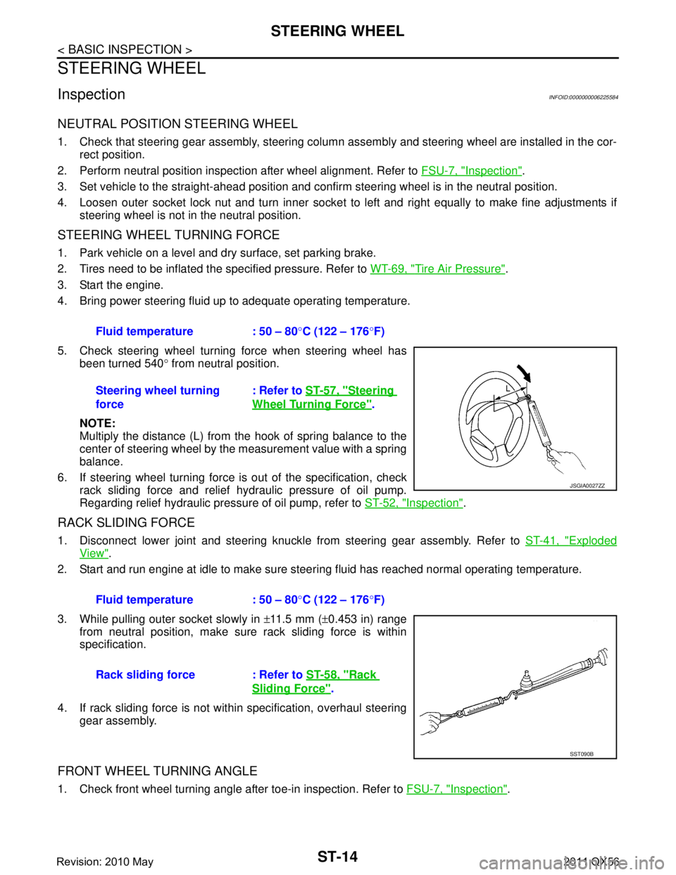
NOTE:
Multiply the distance (L) from the hook of spring balance to the
center of steering wheel by the measurement value with a spring
balance.
6. If steering wheel turning force is out of the specification, check
rack sliding force and relief hydraulic pressure of oil pump.
Regarding relief hydraulic pressure of oil pump, refer to ST-52, "
Inspection".
RACK SLIDING FORCE
1. Disconnect lower joint and steering knuckle from steering gear assembly. Refer to ST-41, "Exploded
View".
2. Start and run engine at idle to make sure steer ing fluid has reached normal operating temperature.
3. While pulling outer socket slowly in ±11.5 mm ( ±0.453 in) range
from neutral position, make sure rack sliding force is within
specification.
4. If rack sliding force is not within specification, overhaul steering gear assembly.
FRONT WHEEL TURNING ANGLE
1. Check front wheel turning angle after toe-in inspection. Refer to FSU-7, "Inspection".
Fluid temperature : 50 – 80
°C (122 – 176 °F)
Steering wheel turning
force : Refer to
ST-57, "
Steering
Wheel Turning Force".
JSGIA0027ZZ
Fluid temperature : 50 – 80 °C (122 – 176 °F)
Rack sliding force : Refer to ST-58, "
Rack
Sliding Force".
SST090B
Revision: 2010 May2011 QX56
Page 5029 of 5598

ST-42
< REMOVAL AND INSTALLATION >
STEERING GEAR AND LINKAGE
Vehicle speed sensitive type
Removal and InstallationINFOID:0000000006225608
REMOVAL
1. Set vehicle to the straight-ahead position.
2. Remove tires.
3. Remove front final drive assembly. Refer to DLN-162, "
Removal and Installation".
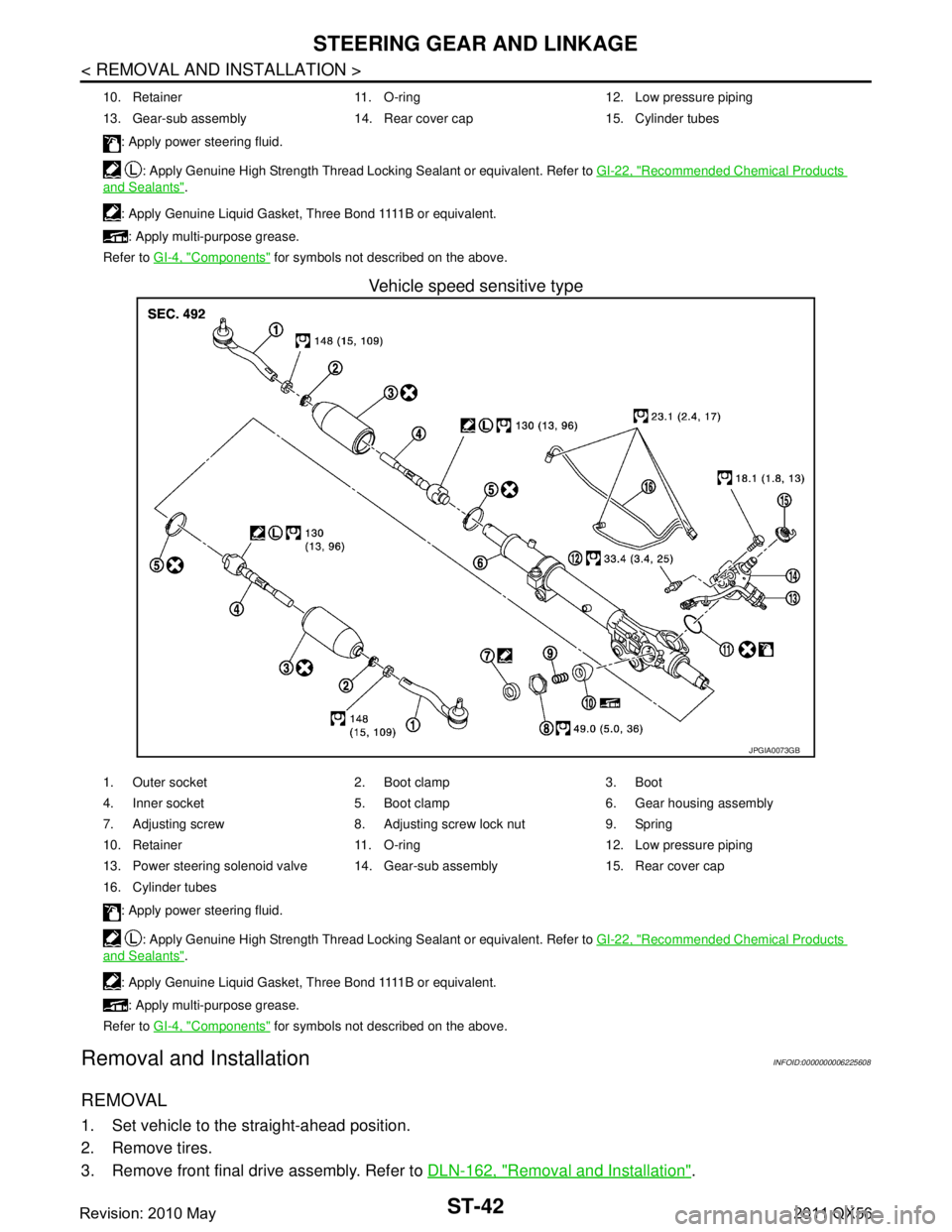
10. Retainer 11. O-ring 12. Low pressure piping
13. Gear-sub assembly 14. Rear cover cap 15. Cylinder tubes
: Apply power steering fluid.
: Apply Genuine High Strength Thread Locking Sealant or equivalent. Refer to GI-22, "
Recommended Chemical Products
and Sealants".
: A p p l y G e n u i n e L i q u i d G a s k e t , T h r e e B o n d 1111 B o r e q u i v a l e n t . : Apply multi-purpose grease.
Refer to GI-4, "
Components" for symbols not described on the above.
JPGIA0073GB
1. Outer socket 2. Boot clamp 3. Boot
4. Inner socket 5. Boot clamp 6. Gear housing assembly
7. Adjusting screw 8. Adjusting screw lock nut 9. Spring
10. Retainer 11. O-ring 12. Low pressure piping
13. Power steering solenoid valve 14. Gear-sub assembly 15. Rear cover cap
16. Cylinder tubes
: Apply power steering fluid.
: Apply Genuine High Strength Thread Locking Sealant or equivalent. Refer to GI-22, "
Recommended Chemical Products
and Sealants".
: A p p l y G e n u i n e L i q u i d G a s k e t , T h r e e B o n d 1111 B o r e q u i v a l e n t . : Apply multi-purpose grease.
Refer to GI-4, "
Components" for symbols not described on the above.
Revision: 2010 May2011 QX56
Page 5034 of 5598

STEERING GEAR AND LINKAGEST-47
< REMOVAL AND INSTALLATION >
C
DE
F
H I
J
K L
M A
B
ST
N
O P
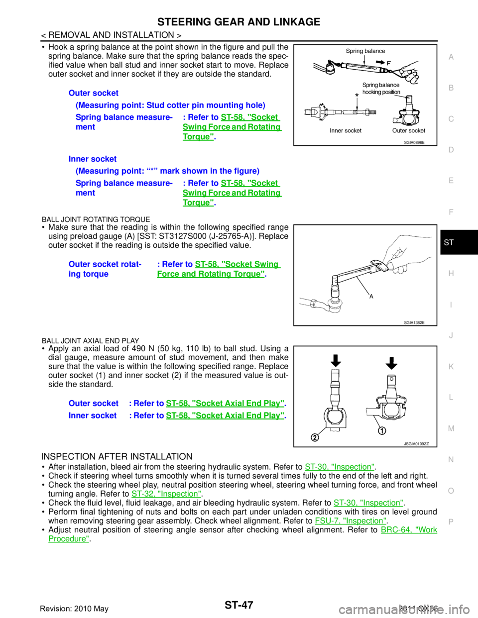
Hook a spring balance at the point shown in the figure and pull the spring balance. Make sure that the spring balance reads the spec-
ified value when ball stud and inner socket start to move. Replace
outer socket and inner socket if they are outside the standard.
BALL JOINT ROTATING TORQUE
Make sure that the reading is within the following specified rangeusing preload gauge (A) [SST: ST3127S000 (J-25765-A)]. Replace
outer socket if the reading is outside the specified value.
BALL JOINT AXIAL END PLAY
Apply an axial load of 490 N (50 kg, 110 lb) to ball stud. Using adial gauge, measure amount of stud movement, and then make
sure that the value is within the following specified range. Replace
outer socket (1) and inner socket (2) if the measured value is out-
side the standard.
INSPECTION AFTER INSTALLATION
After installation, bleed air from the steering hydraulic system. Refer to ST-30, "Inspection".
Check if steering wheel turns smoothly when it is turned several times fully to the end of the left and right.
Check the steering wheel play, neutral position steeri ng wheel, steering wheel turning force, and front wheel
turning angle. Refer to ST-32, "
Inspection".
Check the fluid level, fluid leakage, and air bleeding hydraulic system. Refer to ST-30, "
Inspection".
Perform final tightening of nuts and bolts on each part under unladen conditions with tires on level ground when removing steering gear assembly. Check wheel alignment. Refer to FSU-7, "
Inspection".
Adjust neutral position of steering angle sensor after checking wheel alignment. Refer to BRC-64, "
Work
Procedure".
Outer socket
(Measuring point: Stud cotter pin mounting hole)
Spring balance measure-
ment : Refer to
ST-58, "
Socket
Swing Force and Rotating
To r q u e".
Inner socket (Measuring point: “*” mark shown in the figure)
Spring balance measure-
ment : Refer to
ST-58, "
Socket
Swing Force and Rotating
To r q u e".
Outer socket rotat-
ing torque : Refer to
ST-58, "
Socket Swing
Force and Rotating Torque".
SGIA0896E
SGIA1382E
Outer socket : Refer to ST-58, "Socket Axial End Play".
Inner socket : Refer to ST-58, "
Socket Axial End Play".
JSGIA0109ZZ
Revision: 2010 May2011 QX56
Page 5179 of 5598
![INFINITI QX56 2011 Factory Service Manual
ADDITIONAL SERVICE WHEN REPLACING TRANSMISSION ASSEMBLY
TM-91
< BASIC INSPECTION > [7AT: RE7R01B]
C
EF
G H
I
J
K L
M A
B
TM
N
O P
ADDITIONAL SERVICE WHEN REPL ACING TRANSMISSION ASSEMBLY
DescriptionI INFINITI QX56 2011 Factory Service Manual
ADDITIONAL SERVICE WHEN REPLACING TRANSMISSION ASSEMBLY
TM-91
< BASIC INSPECTION > [7AT: RE7R01B]
C
EF
G H
I
J
K L
M A
B
TM
N
O P
ADDITIONAL SERVICE WHEN REPL ACING TRANSMISSION ASSEMBLY
DescriptionI](/manual-img/42/57033/w960_57033-5178.png)
ADDITIONAL SERVICE WHEN REPLACING TRANSMISSION ASSEMBLY
TM-91
< BASIC INSPECTION > [7AT: RE7R01B]
C
EF
G H
I
J
K L
M A
B
TM
N
O P
ADDITIONAL SERVICE WHEN REPL ACING TRANSMISSION ASSEMBLY
DescriptionINFOID:0000000006233270
Decel G sensor calibration must be performed when replacing A/T assembly.
Special Repair RequirementINFOID:0000000006233271
1.PREPARATION BEFORE CALIBRATION PROCEDURE
1. Park the vehicle on a flat road.
2. Adjust pressure in all tires to the specified value. Refer to WT-69, "
Tire Air Pressure".
>> GO TO 2.
2.PERFORM CALIBRATION
With CONSULT-III
1. Turn ignition switch ON.
CAUTION:
Never start the engine.
2. Select “G SENSOR CALIBRATION” in “Work Support” in “TRANSMISSION”.
3. Touch “START”. CAUTION:
Never give any motion to the vehicle during the calibration.
Is
“completed” displayed?
YES >> GO TO 3.
NO >> Perform the calibration again.
3.CHECK DTC
With CONSULT-III
1. Turn ignition switch OFF and wait 10 seconds or more.
2. Turn ignition switch ON.
3. Select “Self Diagnostic Results” in “ABS”.
Is
“C1145” or “C1146” detected?
YES >> Refer to BRC-51, "DTC Index".
NO >> Calibration end.
Revision: 2010 May2011 QX56