2011 INFINITI QX56 tires
[x] Cancel search: tiresPage 3674 of 5598
MA-4
< PERIODIC MAINTENANCE >
GENERAL MAINTENANCE
PERIODIC MAINTENANCE
GENERAL MAINTENANCE
Explanation of General MaintenanceINFOID:0000000006287728
General maintenance includes those items which shoul d be checked during the normal day-to-day operation
of the vehicle. They are essential if the vehicle is to continue operating properly. The owners can perform
checks and inspections themselves or have their INFINITI dealers do them.
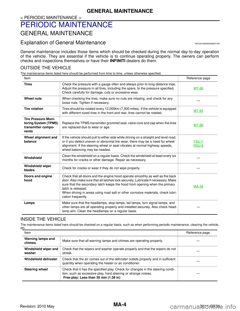
OUTSIDE THE VEHICLE
The maintenance items listed here should be performed fr om time to time, unless otherwise specified.
INSIDE THE VEHICLE
The maintenance items listed here should be checked on a regular basis, such as when performing periodic maintenance, cleaning the vehicle,
etc.
Item Reference page
Tires Check the pressure with a gauge often and always prior to long distance trips.
Adjust the pressure in all tires, including the spare, to the pressure specified.
Check carefully for damage, cuts or excessive wear. WT-69
Wheel nuts
When checking the tires, make sure no nuts are missing, and check for any
loose nuts. Tighten if necessary. —
Tire rotation Tires should be rotated every 12,000km (7,500 miles). If the vehicle is equipped
with different sized tires in the front and rear, tires cannot be rotated. WT-63
Tire Pressure Moni-
toring System (TPMS)
transmitter compo-
nentsReplace the TPMS transmitter grommet seal, valve core and cap when the tires
are replaced due to wear or age.
WT-66
Wheel alignment and
balanceIf the vehicle should pull to either side while driving on a straight and level road,
or if you detect uneven or abnormal tire wear, there may be a need for wheel
alignment. If the steering wheel or seat vibrates at normal highway speeds,
wheel balancing may be needed. FSU-7
RSU-6
Windshield
Clean the windshield on a regular basis. Check the windshield at least every six
months for cracks or other damage. Repair as necessary. —
Windshield wiper
blades Check for cracks or wear if they do not wipe properly. —
Doors and engine
hood Check that all doors and the engine hood operate smoothly as well as the back
door. Also make sure that all latches lock securely. Lubricate if necessary. Make
sure that the secondary latch keeps the hood from opening when the primary
latch is released.
When driving in areas using road salt or other corrosive materials, check lubri-
cation frequently. MA-34
Lamps
Make sure that the headlamps, stop lamps, tail lamps, turn signal lamps, and
other lamps are all operating properly and installed securely. Also check head-
lamp aim. Clean the headlamps on a regular basis. —
Item
Reference page
Warning lamps and
chimes Make sure that all warning lamps and chimes are operating properly. —
Windshield wiper and
washer Check that the wipers and washer operate properly and that the wipers do not
streak.
—
Windshield defroster Check that the air comes out of the defroster outlets properly and in sufficient
quantity when operating the heater or air conditioner. —
Steering wheel Check that it has the specified play. Check for changes in the steering condi-
tion, such as excessive play, hard steering or strange noises.
Free play: Less than 35 mm (1.38 in) —
Revision: 2010 May2011 QX56
Page 3834 of 5598
PARKING BRAKE SYSTEMPB-3
< PERIODIC MAINTENANCE >
C
DE
G H
I
J
K L
M A
B
PB
N
O P
PERIODIC MAINTENANCE
PARKING BRAKE SYSTEM
Inspection and AdjustmentINFOID:0000000006222510
INSPECTION
1. Operate the parking brake pedal with a force of 196 N ( 20 kg, 44 lb). Check that the pedal stroke is within
the specified number of notches. (Check it by listening to clicks of ratchet.)
2. When brake warning lamp turns ON, check that the pedal stroke is within the specified number of
notches. (Check it by listening to clicks of ratchet.)
Inspect Components
Check the following items and replace if necessary.
• Check each component for installation condition such as looseness.
Check the parking brake pedal assembly for bend, damage and cracks.
Check the cables and equalizer for wear, damage and cracks.
Check the parking brake switch. Refer to BRC-118, "
Component Inspection".
ADJUSTMENT
1. Remove the rear tires with power tool.
2. Fix the disc rotor using wheel nuts (2 points at least).
3. Release the parking brake pedal by turning the adjusting nut and loosening the cable.
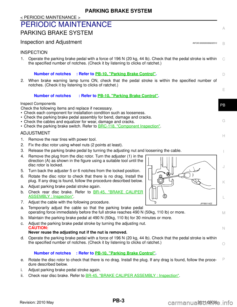
4. Remove the plug from the disc rotor. Turn the adjuster (1) in the
direction (A) as shown in the figure using a suitable tool until the
disc rotor is locked.
5. Turn back the adjuster 5 or 6 notches from the locked position.
6. Rotate the disc rotor to check that there is no drag. Install the plug. If any drag is found, follow the procedure described below.
a. Adjust parking brake pedal stroke again.
b. Check rear disc brake. Refer to BR-45, "
BRAKE CALIPER
ASSEMBLY : Inspection".
7. Adjust the cable with the following procedure.
a. Temporarily adjust the cable so that the parking brake pedal operating force immediately before the full stroke reaches 490 N (50kg, 110 lb) or more.
b. Maintain the parking brake pedal at 490 N (50kg, 110 lb) for 30 minutes or more.
c. Adjust the parking brake pedal st roke by turning the adjusting nut.
CAUTION:
Never reuse the adjusting nu t if the nut is removed.
d. Operate the parking brake pedal with a force of 196 N ( 20 kg, 44 lb). Check that the pedal stroke is within
the specified number of notches. (Check it by listening to clicks of ratchet.)
e. Rotate the disc rotor to check that there is no drag. Install the plug. If any drag is found, follow the proce-
dure described below.
i. Adjust parking brake pedal stroke again.
ii. Check rear disc brake. Refer to BR-45, "
BRAKE CALIPER ASSEMBLY : Inspection".
Number of notches : Refer to
PB-10, "
Parking Brake Control".
Number of notches : Refer to PB-10, "
Parking Brake Control".
Number of notches : Refer to PB-10, "
Parking Brake Control".
JPFIB0114ZZ
Revision: 2010 May2011 QX56
Page 3836 of 5598
PARKING BRAKE CONTROLPB-5
< REMOVAL AND INSTALLATION >
C
DE
G H
I
J
K L
M A
B
PB
N
O P
REMOVAL AND INSTALLATION
PARKING BRAKE CONTROL
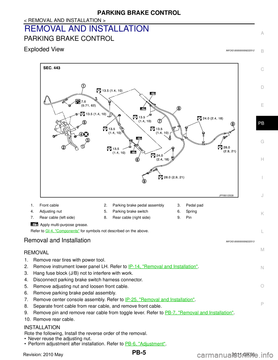
Exploded ViewINFOID:0000000006222512
Removal and InstallationINFOID:0000000006222513
REMOVAL
1. Remove rear tires with power tool.
2. Remove instrument lower panel LH. Refer to IP-14, "
Removal and Installation".
3. Hang fuse block (J/B) not to interfere with work.
4. Disconnect parking brake switch harness connector.
5. Remove adjusting nut and loosen front cable.
6. Remove parking brake pedal assembly.
7. Remove center console assembly. Refer to IP-25, "
Removal and Installation".
8. Separate front cable from rear cable, and remove front cable.
9. Remove pin and remove rear cable from toggle lever. Refer to PB-7, "
Removal and Installation".
10. Remove rear cable.
INSTALLATION
Rote the following, Install the reverse order of the removal.
Never reuse the adjusting nut.
Perform adjustment after installation. Refer to PB-6, "
Adjustment".
1. Front cable 2. Parking brake pedal assembly 3. Pedal pad
4. Adjusting nut 5. Parking brake switch 6. Spring
7. Rear cable (left side) 8. Rear cable (right side) 9. Pin
: Apply multi-purpose grease.
Refer to GI-4, "
Components" for symbols not described on the above.
JPFIB0125GB
Revision: 2010 May2011 QX56
Page 3838 of 5598

PARKING BRAKE SHOEPB-7
< REMOVAL AND INSTALLATION >
C
DE
G H
I
J
K L
M A
B
PB
N
O P
PARKING BRAKE SHOE
Exploded ViewINFOID:0000000006222515
Removal and InstallationINFOID:0000000006222516
REMOVAL
WARNING:
Clean any dust from the parking brake shoes an d back plates with a vacuum dust collector. Never
blow with compressed air.
1. Remove rear tires with power tool.
2. Remove disc rotor. Refer to RAX-7, "
Removal and Installation".
3. Remove anti-rattle pins, retainers, anti-rattle springs, return spring and adjuster spring. CAUTION:
Never drop the removed parts.
4. Remove parking brake shoes, adjuster assembly, and toggle lever. CAUTION:
Never drop the removed parts.
5. For the removal of back plate, refer to RAX-7, "
Removal and Installation".
6. Perform inspection after removal. Refer to PB-8, "
Inspection and Adjustment".
INSTALLATION
Note the following, install in the reverse order of removal.
Apply PBC (Poly Butyl Cuprysil) grease or silicone- based grease to the back plate and brake shoe. Refer to
PB-7, "
Exploded View".
1. Back plate 2. Parking brake shoe 3. Toggle lever
4. Return spring 5. Anti-rattle spring 6. Retainer
7. Anti-rattle pin 8. Adjuster spring 9. Adjuster
: Apply PBC (Poly Butyl Cuprysil) grease or silicone-based grease.
JPFIB0116ZZ
Revision: 2010 May2011 QX56
Page 4203 of 5598
REAR WHEEL HUB AND HOUSINGRAX-7
< REMOVAL AND INSTALLATION >
CEF
G H
I
J
K L
M A
B
RAX
N
O P
REMOVAL AND INSTALLATION
REAR WHEEL HUB AND HOUSING
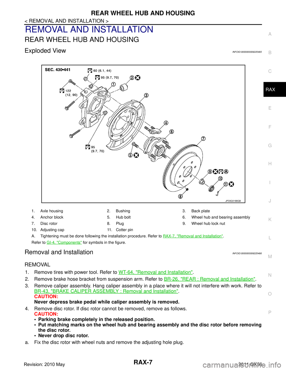
Exploded ViewINFOID:0000000006225465
Removal and InstallationINFOID:0000000006225466
REMOVAL
1. Remove tires with power tool. Refer to WT-64, "Removal and Installation".
2. Remove brake hose bracket from suspension arm. Refer to BR-26, "
REAR : Removal and Installation".
3. Remove caliper assembly. Hang caliper assembly in a place where it will not interfere with work. Refer to BR-43, "
BRAKE CALIPER ASSEMBLY : Removal and Installation".
CAUTION:
Never depress brake pedal while caliper assembly is removed.
4. Remove disc rotor. If disc rotor cannot be removed, remove as follows. CAUTION:
• Parking brake completely in the released position.
Put matching marks on the wheel hub and bear ing assembly and the disc rotor before removing
the disc rotor.
Never drop disc rotor.
a. Fix the disc rotor with wheel nuts and remove the adjusting hole plug.
1. Axle housing 2. Bushing 3. Back plate
4. Anchor block 5. Hub bolt 6. Wheel hub and bearing assembly
7. Disc rotor 8. Plug 9. Wheel hub lock nut
10. Adjusting cap 11. Cotter pin
A. Tightening must be done following the installation procedure. Refer to RAX-7, "
Removal and Installation".
Refer to GI-4, "
Components" for symbols in the figure.
JPDIG0199GB
Revision: 2010 May2011 QX56
Page 4257 of 5598

RSU-2
< PRECAUTION >
PRECAUTIONS
PRECAUTION
PRECAUTIONS
Precautions for SuspensionINFOID:0000000006225656
• When installing rubber bushings, the final tightening must be carried out under unladen conditions with tires
on ground. Spilled oil might shorten the life of rubber bushings. Be sure to wipe off any spilled oil.
- Unladen conditions mean that fuel, engine coolant and l ubricant are full. Spare tire, jack, hand tools and
mats are in designated positions.
After servicing suspension parts, be sure to check wheel alignment.
Self-lock nuts are not reusable. Always use new ones when installing. Since new self-lock nuts are pre-oiled,
tighten as they are.
Revision: 2010 May2011 QX56
Page 4260 of 5598
REAR SUSPENSION ASSEMBLYRSU-5
< PERIODIC MAINTENANCE >
C
DF
G H
I
J
K L
M A
B
RSU
N
O P
PERIODIC MAINTENANCE
REAR SUSPENSION ASSEMBLY
InspectionINFOID:0000000006225660
MOUNTING INSPECTION
Check the mounting conditions (looseness, backlash) of each component and component conditions (wear,
damage) are normal.
BALL JOINT AXIAL END PLAY
Measure axial end play by placing and moving up/down with an iron bar or equivalent between suspension
arm or front lower link and axle assembly.
CAUTION:
• Never depress brake pedal when measuring.
Never perform with tires on level ground.
Be careful not to damage ball joint boot.
SHOCK ABSORBER
Check for oil leakage and damage. Replace it if necessary. Axial end play : Refer to
RSU-20, "
Ball Joint".
Revision: 2010 May2011 QX56
Page 4261 of 5598

RSU-6
< PERIODIC MAINTENANCE >
WHEEL ALIGNMENT
WHEEL ALIGNMENT
InspectionINFOID:0000000006225661
DESCRIPTION
Measure wheel alignment under unladen conditions.
NOTE:
“Unladen conditions” means that fuel, engine coolant, and lubricant are full. Spare tire, jack, hand tools and
mats are in designated positions.
PRELIMINARY CHECK
Check the following:
Tires for improper air pressure and wear
Road wheels for runout. Refer to WT-64, "
Inspection".
Wheel bearing axial end play. Refer to RAX-5, "
Inspection".
Ball joint axial end play of suspension arm and front lower link. Refer to RSU-20, "
Ball Joint".
Shock absorber operation
Each mounting point of axle and suspension for looseness and deformation
Each of front lower link, rear lower link, rear suspension member, suspension arm and shock absorber for
cracks, deformation, and other damage
Vehicle height (posture)
GENERAL INFORMATION AND RECOMMENDATIONS
A four-wheel thrust alignment should be performed.
- This type of alignment is recomm ended for any NISSAN/INFINITI vehicle.
- The four-wheel “thrust” process helps ensure that t he vehicle is properly aligned and the steering wheel is
centered.
- The alignment rack itself should be capable of accepting any NISSAN/INFINITI vehicle.
- The rack should be checked to ensure that it is level.
Make sure the machine is properly calibrated.
- Your alignment equipment should be regularly calib rated in order to give correct information.
- Check with the manufacturer of your specific equi pment for their recommended Service/Calibration Sched-
ule.
ALIGNMENT PROCESS
IMPORTANT:
Use only the alignment specifications listed in this Service Manual.
When displaying the alignment settings, many alignment machines use “indicators”: (Green/red, plus or
minus, Go/No Go). Never use these indicators.
- The alignment specifications programmed into your machine that operate these indicators may not be cor-
rect.
- This may result in an ERROR.
Some newer alignment machines are equipped with an optional “Rolling Compensation” method to “com- pensate” the sensors (alignment targets or head units). Never use this “Rolling Compensation” method.
- Use the “Jacking Compensation Method”. After installi ng the alignment targets or head units, raise the vehi-
cle and rotate the wheels 1/2 turn both ways.
- See Instructions in the alignment machine you're using for more information on this.
AdjustmentINFOID:0000000006225662
CAMBER
Revision: 2010 May2011 QX56