2011 INFINITI QX56 steering
[x] Cancel search: steeringPage 5044 of 5598

SERVICE DATA AND SPECIFICATIONS (SDS)
ST-57
< SERVICE DATA AND SPECIFICATIONS (SDS)
C
D E
F
H I
J
K L
M A
B
ST
N
O P
SERVICE DATA AND SPECIFICATIONS (SDS)
SERVICE DATA AND SPECIFICATIONS (SDS)
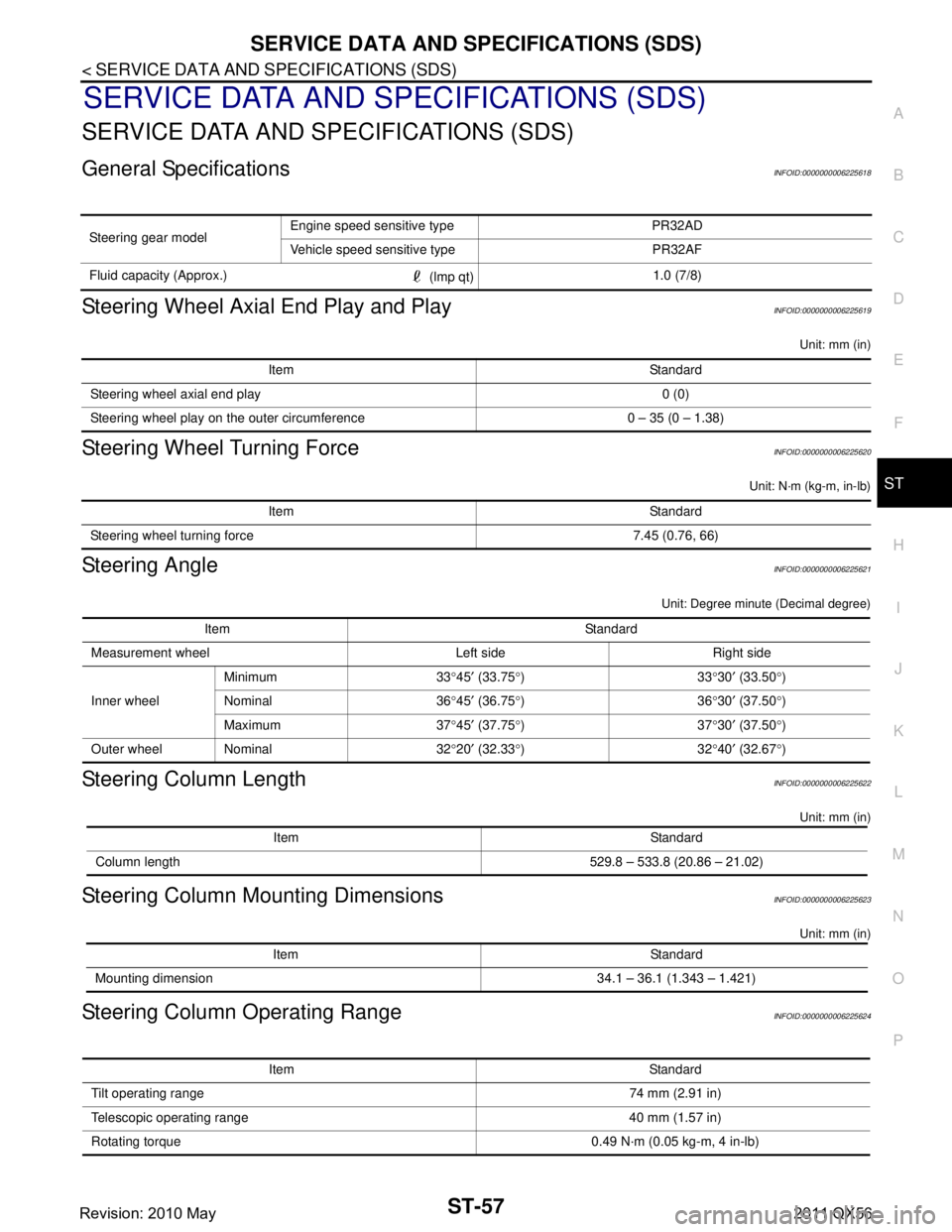
General SpecificationsINFOID:0000000006225618
Steering Wheel Axial End Play and PlayINFOID:0000000006225619
Unit: mm (in)
Steering Wheel Turning ForceINFOID:0000000006225620
Unit: N·m (kg-m, in-lb)
Steering AngleINFOID:0000000006225621
Unit: Degree minute (Decimal degree)
Steering Column LengthINFOID:0000000006225622
Unit: mm (in)
Steering Column Mounting DimensionsINFOID:0000000006225623
Unit: mm (in)
Steering Column Operating RangeINFOID:0000000006225624
Steering gear model Engine speed sensitive type PR32AD
Vehicle speed sensitive type PR32AF
Fluid capacity (Approx.) (lmp qt)1.0 (7/8)
Item Standard
Steering wheel axial end play 0 (0)
Steering wheel play on the outer circumference 0 – 35 (0 – 1.38)
Item Standard
Steering wheel turning force 7.45 (0.76, 66)
Item Standard
Measurement wheel Left side Right side
Inner wheel Minimum 33
°45 ′ (33.75 °)33 °30 ′ (33.50 °)
Nominal 36 °45 ′ (36.75 °)36 °30 ′ (37.50 °)
Maximum 37 °45 ′ (37.75 °)37 °30 ′ (37.50 °)
Outer wheel Nominal 32 °20 ′ (32.33 °)32 °40 ′ (32.67 °)
Item Standard
Column length 529.8 – 533.8 (20.86 – 21.02)
Item Standard
Mounting dimension 34.1 – 36.1 (1.343 – 1.421)
Item Standard
Tilt operating range 74 mm (2.91 in)
Telescopic operating range 40 mm (1.57 in)
Rotating torque 0.49 N· m (0.05 kg-m, 4 in-lb)
Revision: 2010 May2011 QX56
Page 5045 of 5598

ST-58
< SERVICE DATA AND SPECIFICATIONS (SDS)
SERVICE DATA AND SPECIFICATIONS (SDS)
Steering Shaft Sliding Range
INFOID:0000000006225625
Unit: mm (in)
Rack Sliding ForceINFOID:0000000006225626
Unit: N (kg, lb)
Rack StrokeINFOID:0000000006225627
Unit: mm (in)
Socket Swing Force and Rotating TorqueINFOID:0000000006225628
SWING FORCE
Unit: N (kg, lb)
ROTATING TORQUE
Unit: N·m (kg-m, in-lb)
Socket Axial End PlayINFOID:0000000006225629
Unit: mm (in)
Inner Socket LengthINFOID:0000000006225630
Unit: mm (in)
Relief Oil PressureINFOID:0000000006225631
Unit: kPa (bar, kg/cm2, psi)
Item Standard
Sliding range 47 (1.85)
Steering shaft length (extended position) 393 (15.47) or less
Steering shaft runout 1.5 (0.059) or less
Item Standard
Rack sliding force 249.6 – 308.4 (25.5 – 31.4, 56.2 – 69.3)
Item Standard
Rack neutral position, dimension 83.5 (3.287)
Item Spring balance
Outer socket 10.0 – 36.7 (1.02 – 3.74, 2.25 – 8.25)
Inner socket 19.4 – 32.3 (1.98 – 3.29, 4.37 – 7.26)
Item Standard
Outer socket 0.3 – 2.9 (0.03 – 0.3, 2.7 – 26)
Item Standard
Outer socket 0.5 (0.02) or less
Inner socket 0.2 (0.008) or less
Item Standard
Rack neutral position, dimension 110.8 (4.36)
Item Standard
Relief oil pressure 9,500 – 10,300 (95 – 103, 96.9 – 105.1, 1,378 – 1,494)
Revision: 2010 May2011 QX56
Page 5046 of 5598

STC-1
STEERING
C
DE
F
H I
J
K L
M
SECTION STC
A
B
STC
N
O P
CONTENTS
STEERING CONTROL SYSTEM
PRECAUTION ................ ...............................2
PRECAUTIONS .............................................. .....2
Precaution for Supplemental Restraint System
(SRS) "AIR BAG" and "SEAT BELT PRE-TEN-
SIONER" ............................................................. ......
2
Precaution Necessary for Steering Wheel Rota-
tion after Battery Disconnect .....................................
2
SYSTEM DESCRIPTION ..............................4
COMPONENT PARTS ................................... .....4
Component Parts Location .................................. ......4
Component Description .............................................4
Power Steering Control Unit ......................................4
Power Steering Solenoid Valve .................................4
SYSTEM ..............................................................5
EPS SYSTEM ........................................ ......................5
EPS SYSTEM : System De scription .........................5
EPS SYSTEM : Fail-Safe ..........................................6
ECU DIAGNOSIS INFO RMATION ...............8
POWER STEERING CONTROL UNIT ........... .....8
Reference Value ................................................. ......8
Fail-Safe ....................................................................9
WIRING DIAGRAM ......................................10
ELECTRONICALLY CONTROLLED POWER
STEERING SYSTEM ...................................... ....
10
Wiring Diagram ................................................... ....10
BASIC INSPECTION ...................................13
DIAGNOSIS AND REPAIR WORK FLOW .......13
Work Flow ............................................................ ....13
DTC/CIRCUIT DIAGNOSIS .........................14
POWER SUPPLY AND GROUND CIRCUIT ....14
Diagnosis Procedure ........................................... ....14
POWER STEERING SOLENOID VALVE .........16
Component Function Check ....................................16
Diagnosis Procedure ...............................................16
Component Inspection .............................................17
ENGINE SPEED SIGNAL CIRCUIT ..................18
Diagnosis Procedure ........................................... ....18
VEHICLE SPEED SIGNAL CIRCUIT ................20
Diagnosis Procedure ...............................................20
SYMPTOM DIAGNOSIS ..............................22
UNBALANCE STEERING WHEEL TURNING
FORCE (TORQUE VARIATION) .......................
22
Description ........................................................... ....22
Diagnosis Procedure ...............................................22
REMOVAL AND INSTALLATION ...............23
POWER STEERING CONTROL UNIT ..............23
Removal and Installation ..................................... ....23
Revision: 2010 May2011 QX56
Page 5047 of 5598

STC-2
< PRECAUTION >
PRECAUTIONS
PRECAUTION
PRECAUTIONS
Precaution for Supplemental Restraint System (SRS) "AIR BAG" and "SEAT BELT
PRE-TENSIONER"
INFOID:0000000006303358
The Supplemental Restraint System such as “A IR BAG” and “SEAT BELT PRE-TENSIONER”, used along
with a front seat belt, helps to reduce the risk or severi ty of injury to the driver and front passenger for certain
types of collision. This system includes seat belt switch inputs and dual stage front air bag modules. The SRS
system uses the seat belt switches to determine the front air bag deployment, and may only deploy one front
air bag, depending on the severity of a collision and w hether the front occupants are belted or unbelted.
Information necessary to service the system safely is included in the “SRS AIR BAG” and “SEAT BELT” of this
Service Manual.
WARNING:
• To avoid rendering the SRS inopera tive, which could increase the risk of personal injury or death in
the event of a collision that would result in air bag inflation, all maintenance must be performed by
an authorized NISS AN/INFINITI dealer.
Improper maintenance, including in correct removal and installation of the SRS, can lead to personal
injury caused by unintent ional activation of the system. For re moval of Spiral Cable and Air Bag
Module, see the “SRS AIR BAG”.
Do not use electrical test equipmen t on any circuit related to the SRS unless instructed to in this
Service Manual. SRS wiring harnesses can be identi fied by yellow and/or orange harnesses or har-
ness connectors.
PRECAUTIONS WHEN USING POWER TOOLS (AIR OR ELECTRIC) AND HAMMERS
WARNING:
When working near the Air Bag Diagnosis Sensor Unit or other Air Bag System sensors with the ignition ON or engine running, DO NOT use air or electric power tools or strike near the sensor(s)
with a hammer. Heavy vibration could activate the sensor(s) and deploy the air bag(s), possibly
causing serious injury.
When using air or electric power tools or hammers , always switch the ignition OFF, disconnect the
battery, and wait at least 3 minu tes before performing any service.
Precaution Necessary for Steering W heel Rotation after Battery Disconnect
INFOID:0000000006303360
NOTE:
Before removing and installing any control units, first tu rn the push-button ignition switch to the LOCK posi-
tion, then disconnect bot h battery cables.
After finishing work, confirm that all control unit connectors are connected properly, then re-connect both
battery cables.
Always use CONSULT-III to perform self-diagnosis as a part of each function inspection after finishing work.
If a DTC is detected, perform trouble diagnos is according to self-diagnosis results.
For vehicle with steering lock unit, if the battery is disconnected or discharged, the steering wheel will lock and
cannot be turned.
If turning the steering wheel is required with the bat tery disconnected or discharged, follow the operation pro-
cedure below before starting the repair operation.
OPERATION PROCEDURE
1. Connect both battery cables. NOTE:
Supply power using jumper cables if battery is discharged.
2. Turn the push-button ignition switch to ACC position. (At this time, the steering lock will be released.)
3. Disconnect both battery cables. The steering lock wi ll remain released with both battery cables discon-
nected and the steering wheel can be turned.
4. Perform the necessary repair operation.
Revision: 2010 May2011 QX56
Page 5048 of 5598

PRECAUTIONSSTC-3
< PRECAUTION >
C
DE
F
H I
J
K L
M A
B
STC
N
O P
5. When the repair work is completed, re-connect both battery cables. With the brake pedal released, turn
the push-button ignition switch from ACC position to ON position, then to LOCK position. (The steering
wheel will lock when the push-button ignition switch is turned to LOCK position.)
6. Perform self-diagnosis check of a ll control units using CONSULT-III.
Revision: 2010 May2011 QX56
Page 5049 of 5598

STC-4
< SYSTEM DESCRIPTION >
COMPONENT PARTS
SYSTEM DESCRIPTION
COMPONENT PARTS
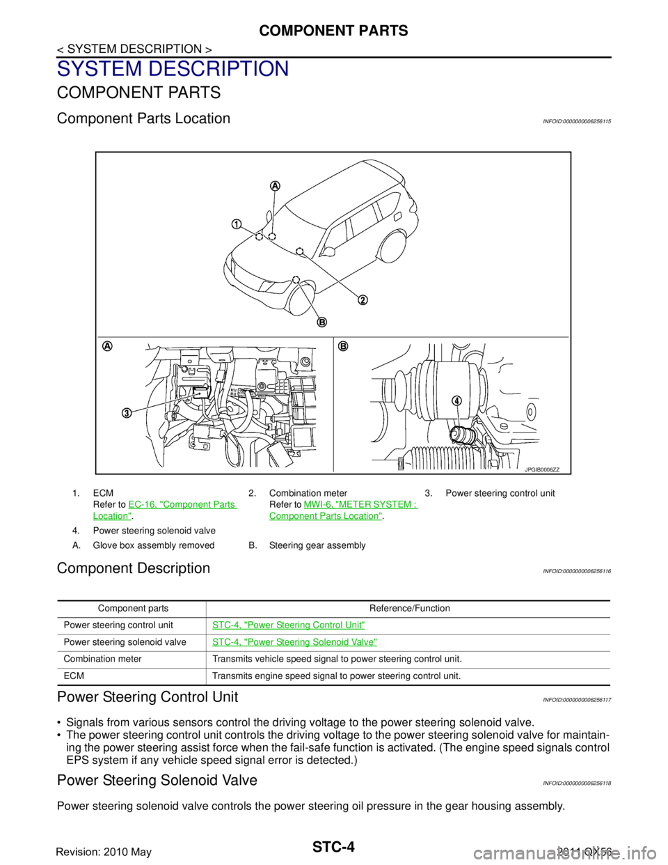
Component Parts LocationINFOID:0000000006256115
Component DescriptionINFOID:0000000006256116
Power Steering Control UnitINFOID:0000000006256117
Signals from various sensors control the driving voltage to the power steering solenoid valve.
The power steering control unit controls the driving vo ltage to the power steering solenoid valve for maintain-
ing the power steering assist force when the fail-safe function is activated. (The engine speed signals control
EPS system if any vehicle s peed signal error is detected.)
Power Steering Solenoid ValveINFOID:0000000006256118
Power steering solenoid valve controls the power steering oil pressure in the gear housing assembly.
1. ECM
Refer to EC-16, "
Component Parts
Location". 2. Combination meter
Refer to MWI-6, "
METER SYSTEM :
Component Parts Location". 3. Power steering control unit
4. Power steering solenoid valve
A. Glove box assembly removed B. Steering gear assembly
JPGIB0006ZZ
Component parts Reference/Function
Power steering control unit STC-4, "
Power Steering Control Unit"
Power steering solenoid valveSTC-4, "Power Steering Solenoid Valve"
Combination meter Transmits vehicle speed signal to power steering control unit.
ECM Transmits engine speed signal to power steering control unit.
Revision: 2010 May2011 QX56
Page 5050 of 5598

SYSTEMSTC-5
< SYSTEM DESCRIPTION >
C
DE
F
H I
J
K L
M A
B
STC
N
O P
SYSTEM
EPS SYSTEM
EPS SYSTEM : System DescriptionINFOID:0000000006256119
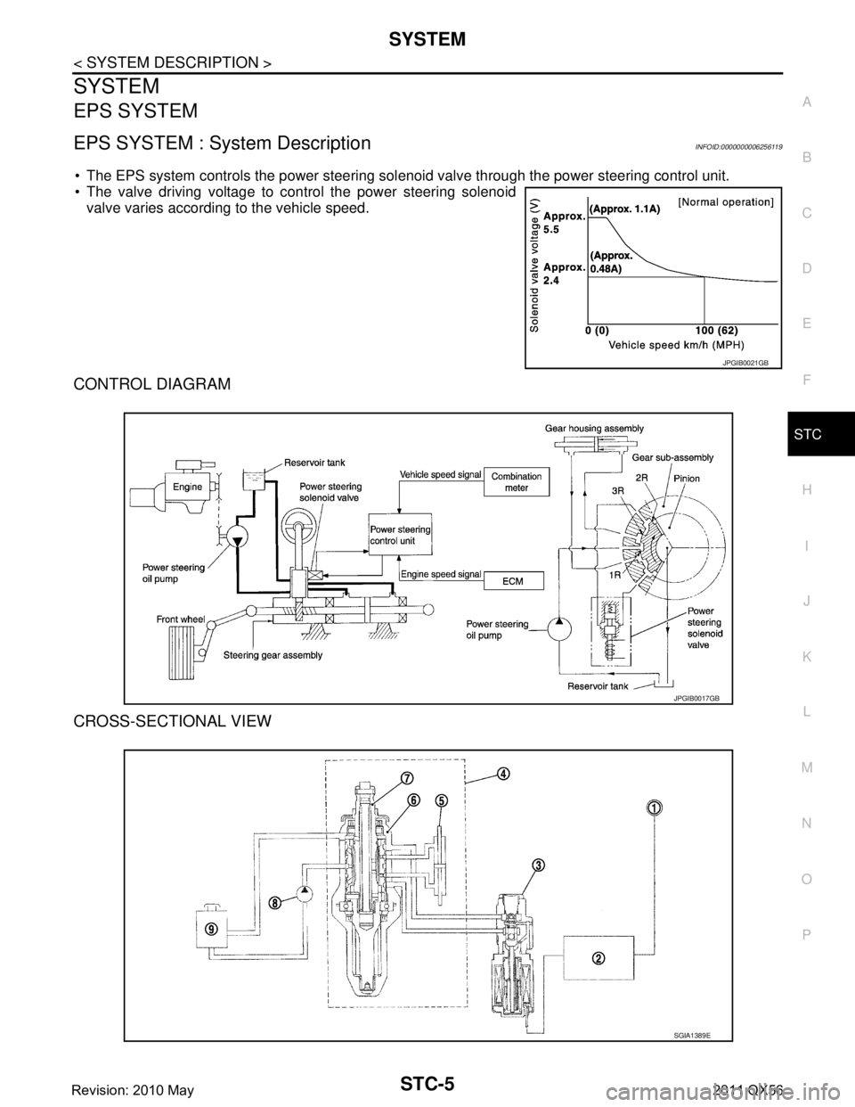
The EPS system controls the power steering sol enoid valve through the power steering control unit.
The valve driving voltage to control the power steering solenoid
valve varies according to the vehicle speed.
CONTROL DIAGRAM
CROSS-SECTIONAL VIEW
JPGIB0021GB
JPGIB0017GB
SGIA1389E
Revision: 2010 May2011 QX56
Page 5051 of 5598

STC-6
< SYSTEM DESCRIPTION >
SYSTEM
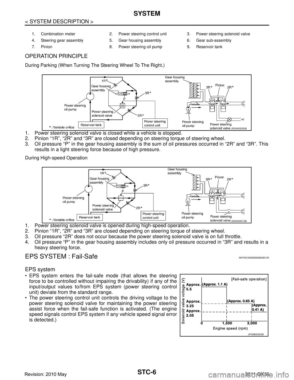
OPERATION PRINCIPLE
During Parking (When Turning The Steering Wheel To The Right.)
1. Power steering solenoid valve is closed while a vehicle is stopped.
2. Pinion “1R”, “2R” and “3R” are closed depending on steering torque of steering wheel.
3. Oil pressure “P” in the gear housing assembly is the sum of oil pressures occurred in “2R” and “3R”. Thisresults in a light steering force because of high pressure.
During High-speed Operation
1. Power steering solenoid valve is opened during high-speed operation.
2. Pinion “1R”, “2R” and “3R” are closed depending on steering torque of steering wheel.
3. Oil pressure “2R” does not occur because the pow er steering solenoid valve is on full throttle.
4. Oil pressure “P” in the gear housing assembly includes only oil pressure occurred in “3R” and results in a heavy steering force.
EPS SYSTEM : Fail-Safe INFOID:0000000006256120
EPS system
EPS system enters the fail-safe mode (that allows the steering
force to be controlled without impairi ng the drivability) if any of the
input/output values to/from EPS system (power steering control
unit) deviate from the standard range.
The power steering control unit controls the driving voltage to the
power steering solenoid valve for maintaining the power steering
assist force when the fail-safe function is activated. (The engine
speed signals control EPS system if any vehicle speed signal error
is detected.)
1. Combination meter 2. Power steering control unit 3. Power steering solenoid valve
4. Steering gear assembly 5. Gear housing assembly 6. Gear sub-assembly
7. Pinion 8. Power steering oil pump 9. Reservoir tank
JSGIA0020GB
JSGIA0021GB
JPGIB0022GB
Revision: 2010 May2011 QX56