2011 INFINITI QX56 tire pressure
[x] Cancel search: tire pressurePage 4768 of 5598
COLLISION DIAGNOSISSR-5
< BASIC INSPECTION >
C
DE
F
G
I
J
K L
M A
B
SR
N
O P
BASIC INSPECTION
COLLISION DIAGNOSIS
FOR FRONTAL COLLISION
FOR FRONTAL COLLISION : When SR S is activated in a collisionINFOID:0000000006113080
CAUTION:
Due to varying models and option levels, not all parts listed in the chart below apply to all vehicles.
WORK PROCEDURE
1. Before performing any of the following steps, ensur e that all vehicle body and structural repairs have been
completed.
2. Replace the diagnosis sensor unit.
3. Remove the front air bag modules, crash zone sensor , bracket and seat belt pre-tensioner assemblies.
4. Check the SRS components using the table below: Replace any SRS components showing visible signs of damage. (dents, cracks and deformation, etc.)
5. Install new front air bag modules, crash zone sens or assembly, bracket and seat belt pre-tensioner
assemblies.
6. Perform self-diagnosis using CONSULT-III or air bag warning lamp. Refer to SRC-14, "
Description" for
details. Ensure entire SRS operates properly.
7. After the work is completed, perform self-diagnosis to check that no malfunction is detected. Refer to
SRC-14, "
Description".
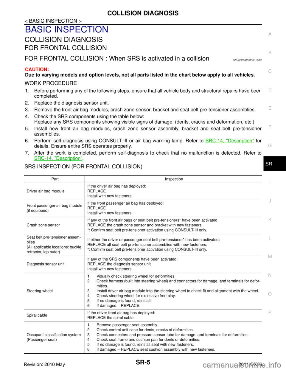
SRS INSPECTION (FOR FRONTAL COLLISION)
Part Inspection
Driver air bag module If the driver air bag has deployed:
REPLACE
Install with new fasteners.
Front passenger air bag module
(if equipped) If the front passenger air bag has deployed:
REPLACE
Install with new fasteners.
Crash zone sensor If any of the front air bags or seat belt pre-tensioners* have been activated:
REPLACE the crash zone sensor and bracket with new fasteners.
*: Confirm seat belt pre-tensioner activation using CONSULT-III only.
Seat belt pre-tensioner assem-
blies
(All applicable locations: buckle,
retractor, lap outer) If either the driver or passenger seat belt pre-tensioner* has been activated:
REPLACE all seat belt pre-tensioner assemblies with new fasteners.
*: Confirm seat belt pre-tensioner activation using CONSULT-III only.
Diagnosis sensor unit If any of the SRS components have been activated:
REPLACE the diagnosis sensor unit.
Install with new fasteners.
Steering wheel 1. Visually check steering wheel for deformities.
2. Check harness (built into steering wheel) and connectors for damage, and terminals for defor-
mities.
3. Install driver air bag module into the steering wheel to check fit and alignment with the wheel.
4. Check steering wheel for excessive free play.
5. If no damage is found, reinstall.
6. If damaged − REPLACE.
Spiral cable If the driver front air bag has deployed:
REPLACE the spiral cable.
Occupant classification system
(Passenger seat) 1. Remove passenger seat assembly.
2. Check control unit case for dents, cracks of deformities.
3. Check connectors and pressure sensor tube for damage, and terminals for deformities.
4. Check seat frame and cushion pan for dents or deformities.
5. If no damage is found, reinstall seat with new fasteners.
6. If damaged
− REPLACE seat cushion assembly with new fasteners.
Revision: 2010 May2011 QX56
Page 4770 of 5598
COLLISION DIAGNOSISSR-7
< BASIC INSPECTION >
C
DE
F
G
I
J
K L
M A
B
SR
N
O P
FOR SIDE AND ROLLOVER COLLISION
FOR SIDE AND ROLLOVER CO LLISION : When SRS is activated in a collision
INFOID:0000000006113082
CAUTION:
Due to varying models and option levels, not all parts listed in the chart below apply to all vehicles.
WORK PROCEDURE
1. Before performing any of the following steps, ensur e that all vehicle body and structural repairs have been
completed.
2. Replace the following components: Front seat back assembly (on the side on which side air bag is activated)
Door finisher (on the side on which door-mounted curtain air bag is activated)
Pop-up roll bar assemblies and pop-up roll bar covers
Side air bag (satellite) sensor LH/RH (on the side on which side air bag is activated)
Diagnosis sensor unit
Seat belt pre-tensioner assemblies
3. Check the SRS components and the related parts using the following table. Replace any SRS components and the related parts s howing visible signs of damage. (dents, cracks,
deformation, etc.)
4. Perform self-diagnosis using CONSULT-III and “AIR BAG” warning lamp. Refer to SRC-14, "
Description"
for details. Make sure entire SRS operates properly.
5. After the work is completed, perform self-diagnosis to check that no malfunction is detected. Refer to
SRC-14, "
Description".
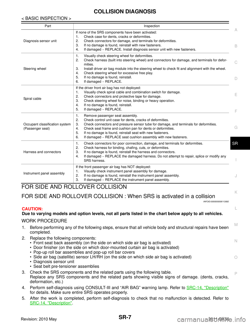
Diagnosis sensor unit If none of the SRS components have been activated:
1. Check case for dents, cracks or deformities.
2. Check connectors for damage, and terminals for deformities.
3. If no damage is found, reinstall with new fasteners.
4. If damaged
− REPLACE. Install diagnosis sensor unit with new fasteners.
Steering wheel 1. Visually check steering wheel for deformities.
2. Check harness (built into steering wheel) and connectors for damage, and terminals for defor-
mities.
3. Install driver air bag module into the steering wheel to check fit and alignment with the wheel.
4. Check steering wheel for excessive free play.
5. If no damage is found, reinstall.
6. If damaged − REPLACE.
Spiral cable If the driver front air bag has not deployed:
1. Visually check spiral cable and combination switch for damage.
2. Check connectors and protective tape for damage.
3. Check steering wheel for noise, binding or heavy operation.
4. If no damage is found, reinstall.
5. If damaged
− REPLACE.
Occupant classification system
(Passenger seat) 1. Remove passenger seat assembly.
2. Check control unit case for dents, cracks of deformities.
3. Check connectors and pressure sensor tube for damage, and terminals for deformities.
4. Check seat frame and cushion pan for dents or deformities.
5. If no damage is found, reinstall seat with new fasteners.
6. If damaged
− REPLACE seat cushion assembly with new fasteners.
Harness and connectors 1. Check connectors for poor connection, damage, and terminals for deformities.
2. Check harness for binding, chafing, cuts, or deformities.
3. If no damage is found, reinstall the harness and connectors.
4. If damaged
− REPLACE the damaged harness. Do not attempt to repair, splice or modify any
SRS harness.
Instrument panel assembly If the front passenger air bag has NOT deployed:
1. Visually check instrument panel assembly for damage.
2. If no damage is found, reinstall the instrument panel assembly.
3. If damaged
− REPLACE the instrument panel assembly.
Part Inspection
Revision: 2010 May2011 QX56
Page 5001 of 5598
ST-14
< BASIC INSPECTION >
STEERING WHEEL
STEERING WHEEL
InspectionINFOID:0000000006225584
NEUTRAL POSITION STEERING WHEEL
1. Check that steering gear assembly, steering column assembly and steering wheel are installed in the cor-
rect position.
2. Perform neutral position inspection after wheel alignment. Refer to FSU-7, "
Inspection".
3. Set vehicle to the straight-ahead position and c onfirm steering wheel is in the neutral position.
4. Loosen outer socket lock nut and turn inner socket to left and right equally to make fine adjustments if steering wheel is not in the neutral position.
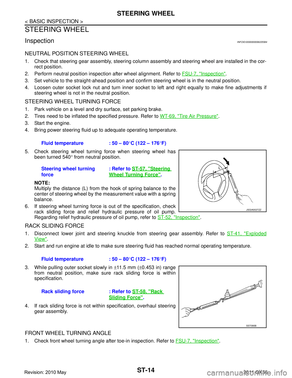
STEERING WHEEL TURNING FORCE
1. Park vehicle on a level and dry surface, set parking brake.
2. Tires need to be inflated the specified pressure. Refer to WT-69, "
Tire Air Pressure".
3. Start the engine.
4. Bring power steering fluid up to adequate operating temperature.
5. Check steering wheel turning force when steering wheel has been turned 540 ° from neutral position.
NOTE:
Multiply the distance (L) from the hook of spring balance to the
center of steering wheel by the measurement value with a spring
balance.
6. If steering wheel turning force is out of the specification, check
rack sliding force and relief hydraulic pressure of oil pump.
Regarding relief hydraulic pressure of oil pump, refer to ST-52, "
Inspection".
RACK SLIDING FORCE
1. Disconnect lower joint and steering knuckle from steering gear assembly. Refer to ST-41, "Exploded
View".
2. Start and run engine at idle to make sure steer ing fluid has reached normal operating temperature.
3. While pulling outer socket slowly in ±11.5 mm ( ±0.453 in) range
from neutral position, make sure rack sliding force is within
specification.
4. If rack sliding force is not within specification, overhaul steering gear assembly.
FRONT WHEEL TURNING ANGLE
1. Check front wheel turning angle after toe-in inspection. Refer to FSU-7, "Inspection".
Fluid temperature : 50 – 80
°C (122 – 176 °F)
Steering wheel turning
force : Refer to
ST-57, "
Steering
Wheel Turning Force".
JSGIA0027ZZ
Fluid temperature : 50 – 80 °C (122 – 176 °F)
Rack sliding force : Refer to ST-58, "
Rack
Sliding Force".
SST090B
Revision: 2010 May2011 QX56
Page 5029 of 5598
ST-42
< REMOVAL AND INSTALLATION >
STEERING GEAR AND LINKAGE
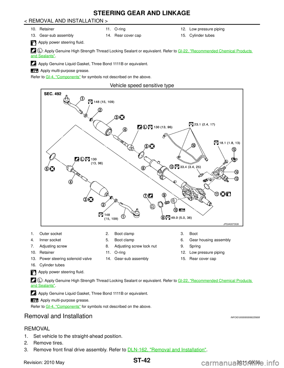
Vehicle speed sensitive type
Removal and InstallationINFOID:0000000006225608
REMOVAL
1. Set vehicle to the straight-ahead position.
2. Remove tires.
3. Remove front final drive assembly. Refer to DLN-162, "
Removal and Installation".
10. Retainer 11. O-ring 12. Low pressure piping
13. Gear-sub assembly 14. Rear cover cap 15. Cylinder tubes
: Apply power steering fluid.
: Apply Genuine High Strength Thread Locking Sealant or equivalent. Refer to GI-22, "
Recommended Chemical Products
and Sealants".
: A p p l y G e n u i n e L i q u i d G a s k e t , T h r e e B o n d 1111 B o r e q u i v a l e n t . : Apply multi-purpose grease.
Refer to GI-4, "
Components" for symbols not described on the above.
JPGIA0073GB
1. Outer socket 2. Boot clamp 3. Boot
4. Inner socket 5. Boot clamp 6. Gear housing assembly
7. Adjusting screw 8. Adjusting screw lock nut 9. Spring
10. Retainer 11. O-ring 12. Low pressure piping
13. Power steering solenoid valve 14. Gear-sub assembly 15. Rear cover cap
16. Cylinder tubes
: Apply power steering fluid.
: Apply Genuine High Strength Thread Locking Sealant or equivalent. Refer to GI-22, "
Recommended Chemical Products
and Sealants".
: A p p l y G e n u i n e L i q u i d G a s k e t , T h r e e B o n d 1111 B o r e q u i v a l e n t . : Apply multi-purpose grease.
Refer to GI-4, "
Components" for symbols not described on the above.
Revision: 2010 May2011 QX56
Page 5053 of 5598
STC-8
< ECU DIAGNOSIS INFORMATION >
POWER STEERING CONTROL UNIT
ECU DIAGNOSIS INFORMATION
POWER STEERING CONTROL UNIT
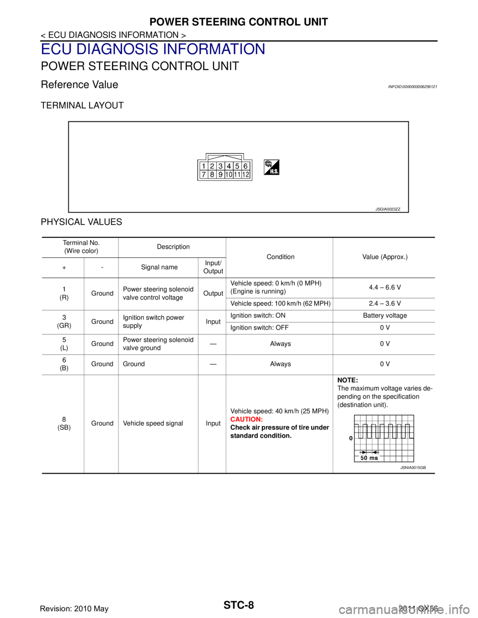
Reference Value INFOID:0000000006256121
TERMINAL LAYOUT
PHYSICAL VALUES
JSGIA0023ZZ
Te r m i n a l N o .(Wire color) Description
Condition Value (Approx.)
+ - Signal name Input/
Output
1
(R) GroundPower steering
solenoid
valve control voltage OutputVehicle speed: 0 km/h (0 MPH)
(Engine is running)
4.4 – 6.6 V
Vehicle speed: 100 km/h (62 MPH) 2.4 – 3.6 V
3
(GR) GroundIgnition switch power
supply InputIgnition switch: ON Battery voltage
Ignition switch: OFF 0 V
5
(L) Ground
Power steering
solenoid
valve ground —Always 0 V
6
(B) Ground Ground — Always 0 V
8
(SB) Ground Vehicle speed signal Input Vehicle speed: 40 km/h (25 MPH)
CAUTION:
Check air pressure of tire under
standard condition.NOTE:
The maximum voltage varies de-
pending on the specification
(destination unit).
JSNIA0015GB
Revision: 2010 May2011 QX56
Page 5065 of 5598
STC-20
< DTC/CIRCUIT DIAGNOSIS >
VEHICLE SPEED SIGNAL CIRCUIT
VEHICLE SPEED SIGNAL CIRCUIT
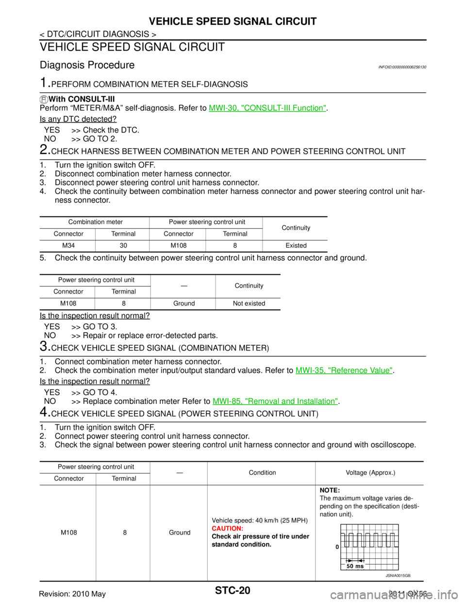
Diagnosis ProcedureINFOID:0000000006256130
1.PERFORM COMBINATION METER SELF-DIAGNOSIS
With CONSULT-III
Perform “METER/M&A” self-diagnosis. Refer to MWI-30, "
CONSULT-III Function".
Is any DTC detected?
YES >> Check the DTC.
NO >> GO TO 2.
2.CHECK HARNESS BETWEEN COMBINATION ME TER AND POWER STEERING CONTROL UNIT
1. Turn the ignition switch OFF.
2. Disconnect combination meter harness connector.
3. Disconnect power steering control unit harness connector.
4. Check the continuity between combination meter harness connector and power steering control unit har-
ness connector.
5. Check the continuity between power st eering control unit harness connector and ground.
Is the inspection result normal?
YES >> GO TO 3.
NO >> Repair or replace error-detected parts.
3.CHECK VEHICLE SPEED SIGN AL (COMBINATION METER)
1. Connect combination meter harness connector.
2. Check the combination meter input/output standard values. Refer to MWI-35, "
Reference Value".
Is the inspection result normal?
YES >> GO TO 4.
NO >> Replace combination meter Refer to MWI-85, "
Removal and Installation".
4.CHECK VEHICLE SPEED SIGNAL (POWER STEERING CONTROL UNIT)
1. Turn the ignition switch OFF.
2. Connect power steering control unit harness connector.
3. Check the signal between power steering cont rol unit harness connector and ground with oscilloscope.
Combination meter Power steering control unit
Continuity
Connector Terminal Connector Terminal
M34 30 M108 8 Existed
Power steering control unit —Continuity
Connector Terminal
M108 8 Ground Not existed
Power steering control unit — Condition Voltage (Approx.)
Connector Terminal
M108 8 Ground Vehicle speed: 40 km/h (25 MPH)
CAUTION:
Check air pressure of tire under
standard condition.NOTE:
The maximum voltage varies de-
pending on the specification (desti-
nation unit).
JSNIA0015GB
Revision: 2010 May2011 QX56
Page 5179 of 5598
![INFINITI QX56 2011 Factory Service Manual
ADDITIONAL SERVICE WHEN REPLACING TRANSMISSION ASSEMBLY
TM-91
< BASIC INSPECTION > [7AT: RE7R01B]
C
EF
G H
I
J
K L
M A
B
TM
N
O P
ADDITIONAL SERVICE WHEN REPL ACING TRANSMISSION ASSEMBLY
DescriptionI INFINITI QX56 2011 Factory Service Manual
ADDITIONAL SERVICE WHEN REPLACING TRANSMISSION ASSEMBLY
TM-91
< BASIC INSPECTION > [7AT: RE7R01B]
C
EF
G H
I
J
K L
M A
B
TM
N
O P
ADDITIONAL SERVICE WHEN REPL ACING TRANSMISSION ASSEMBLY
DescriptionI](/manual-img/42/57033/w960_57033-5178.png)
ADDITIONAL SERVICE WHEN REPLACING TRANSMISSION ASSEMBLY
TM-91
< BASIC INSPECTION > [7AT: RE7R01B]
C
EF
G H
I
J
K L
M A
B
TM
N
O P
ADDITIONAL SERVICE WHEN REPL ACING TRANSMISSION ASSEMBLY
DescriptionINFOID:0000000006233270
Decel G sensor calibration must be performed when replacing A/T assembly.
Special Repair RequirementINFOID:0000000006233271
1.PREPARATION BEFORE CALIBRATION PROCEDURE
1. Park the vehicle on a flat road.
2. Adjust pressure in all tires to the specified value. Refer to WT-69, "
Tire Air Pressure".
>> GO TO 2.
2.PERFORM CALIBRATION
With CONSULT-III
1. Turn ignition switch ON.
CAUTION:
Never start the engine.
2. Select “G SENSOR CALIBRATION” in “Work Support” in “TRANSMISSION”.
3. Touch “START”. CAUTION:
Never give any motion to the vehicle during the calibration.
Is
“completed” displayed?
YES >> GO TO 3.
NO >> Perform the calibration again.
3.CHECK DTC
With CONSULT-III
1. Turn ignition switch OFF and wait 10 seconds or more.
2. Turn ignition switch ON.
3. Select “Self Diagnostic Results” in “ABS”.
Is
“C1145” or “C1146” detected?
YES >> Refer to BRC-51, "DTC Index".
NO >> Calibration end.
Revision: 2010 May2011 QX56
Page 5180 of 5598
![INFINITI QX56 2011 Factory Service Manual
TM-92
< BASIC INSPECTION >[7AT: RE7R01B]
ADDITIONAL SERVICE WHEN RE
PLACING CONTROL VALVE & TCM
ADDITIONAL SERVICE WHEN REPLACING CONTROL VALVE & TCM
DescriptionINFOID:0000000006233274
Decel G sensor INFINITI QX56 2011 Factory Service Manual
TM-92
< BASIC INSPECTION >[7AT: RE7R01B]
ADDITIONAL SERVICE WHEN RE
PLACING CONTROL VALVE & TCM
ADDITIONAL SERVICE WHEN REPLACING CONTROL VALVE & TCM
DescriptionINFOID:0000000006233274
Decel G sensor](/manual-img/42/57033/w960_57033-5179.png)
TM-92
< BASIC INSPECTION >[7AT: RE7R01B]
ADDITIONAL SERVICE WHEN RE
PLACING CONTROL VALVE & TCM
ADDITIONAL SERVICE WHEN REPLACING CONTROL VALVE & TCM
DescriptionINFOID:0000000006233274
Decel G sensor calibration must be performed when replacing control valve & TCM.
Special Repair RequirementINFOID:0000000006233275
1.PREPARATION BEFORE CALIBRATION PROCEDURE
1. Park the vehicle on a flat road.
2. Adjust pressure in all tires to the specified value. Refer to WT-69, "
Tire Air Pressure".
>> GO TO 2.
2.PERFORM CALIBRATION
With CONSULT-III
1. Turn ignition switch ON.
CAUTION:
Never start the engine.
2. Select “G SENSOR CALIBRATION” in “Work Support” in “TRANSMISSION”.
3. Touch “START”. CAUTION:
Never give any motion to the vehicle during the calibration.
Is
“completed” displayed?
YES >> GO TO 3.
NO >> Perform the calibration again.
3.CHECK DTC
With CONSULT-III
1. Turn ignition switch OFF and wait 10 seconds or more.
2. Turn ignition switch ON.
3. Select “Self Diagnostic Results” in “ABS”.
Is
“C1145” or “C1146” detected?
YES >> Refer to BRC-51, "DTC Index".
NO >> Calibration end.
Revision: 2010 May2011 QX56