Page 5294 of 5598
![INFINITI QX56 2011 Factory Service Manual
TM-206
< UNIT REMOVAL AND INSTALLATION >[7AT: RE7R01B]
TRANSMISSION ASSEMBLY
8. Remove exhaust front tube (RH and LH) and main muffler. Refer to
EX-5, "Exploded View".
9. Separate propeller shaft as INFINITI QX56 2011 Factory Service Manual
TM-206
< UNIT REMOVAL AND INSTALLATION >[7AT: RE7R01B]
TRANSMISSION ASSEMBLY
8. Remove exhaust front tube (RH and LH) and main muffler. Refer to
EX-5, "Exploded View".
9. Separate propeller shaft as](/manual-img/42/57033/w960_57033-5293.png)
TM-206
< UNIT REMOVAL AND INSTALLATION >[7AT: RE7R01B]
TRANSMISSION ASSEMBLY
8. Remove exhaust front tube (RH and LH) and main muffler. Refer to
EX-5, "Exploded View".
9. Separate propeller shaft assembly. Refer to DLN-144, "
Removal and Installation".
NOTE:
Cap or plug opening to prevent fluid from spilling.
10. Remove front under cover with a power tool. Refer to EXT-25, "
Removal and Installation".
11. Remove protector A and B. Refer to SCS-32, "
FRONT TUBE ASSEMBLY : Exploded View".
12. Remove front suspension rear cross member.
13. Remove crankshaft position sensor (POS) from A/T assembly. Refer to EM-106, "
Exploded View".
CAUTION:
Never subject it to impact by dropping or hitting it.
Never disassemble.
Never allow metal filings, etc. to ge t on the sensor's front edge magnetic area.
Never place in an area affected by magnetism.
14. Remove rear plate cover. Refer to EM-54, "
Exploded View".
15. Turn crankshaft, and remove the four tight ening bolts for drive plate and torque converter.
CAUTION:
When turning the crankshaft, turn it clockw ise as viewed from the front of the engine.
16. Remove A/T fluid cooler tube A and D. Refer to TM-202, "
Exploded View".
NOTE:
Cap or plug openings to prevent fluid from spilling.
17. Remove bolts fixing A/T assembly to engine with a power tool.
18. Disconnect connector from A/T assembly.
19. Remove harness and brackets from A/T assembly.
20. Remove A/T assembly from the vehicle. CAUTION:
Secure torque converter to prevent it from dropping.
Secure A/T assembly to a transmission jack.
21. Remove air breather hose and bracket. Refer to TM-199, "
2WD
: Exploded View".
22. Remove manual lever from A/T assembly. Refer to TM-178,
"Exploded View".
INSTALLATION
Note the following, and Install in the reverse order of removal.
Check fitting of dowel pin ( ).
ATA0025D
JSDIA1597ZZ
Revision: 2010 May2011 QX56
Page 5451 of 5598

WT-1
SUSPENSION
C
DF
G H
I
J
K L
M
SECTION WT
A
B
WT
N
O PCONTENTS
ROAD WHEELS & TIRES
PRECAUTION ................ ...............................3
PRECAUTIONS .............................................. .....3
Precaution for Supplemental Restraint System
(SRS) "AIR BAG" and "SEAT BELT PRE-TEN-
SIONER" ............................................................. ......
3
Precaution Necessary for Steering Wheel Rota-
tion after Battery Disconnect .....................................
3
Service Notice or Precautions for TPMS ...................4
Service Notice or Precautions for Road Wheel .........4
PREPARATION ............................................5
PREPARATION .............................................. .....5
Special Service Tools .......................................... ......5
Commercial Service Tools ........................................5
SYSTEM DESCRIPTION ..............................6
COMPONENT PARTS ................................... .....6
Component Parts Location .................................. ......6
Component Description .............................................7
Low Tire Pressure Warning Control Unit ...................7
Transmitter ................................................................7
Tire Pressure Receiver .............................................8
Low Tire Pressure Warning Lamp .............................8
SYSTEM ..............................................................9
System Description ............................................. ......9
Tire Inflation Indicator Function ...............................10
DIAGNOSIS SYSTEM (LOW TIRE PRES-
SURE WARNING CONTROL UNIT) ..................
12
CONSULT-III Function ........................................ ....12
ECU DIAGNOSIS INFORMATION ..............14
LOW TIRE PRESSURE WARNING CON-
TROL UNIT ..................................................... ....
14
Reference Value ................................................. ....14
DTC Inspection Priority Chart .................................17
DTC Index ...............................................................18
WIRING DIAGRAM ......................................19
TIRE PRESSURE MONITORING SYSTEM ......19
Wiring Diagram .................................................... ....19
BASIC INSPECTION ...................................25
DIAGNOSIS AND REPAIR WORK FLOW .......25
Work Flow ............................................................ ....25
ADDITIONAL SERVICE WHEN REPLACING
LOW TIRE PRESSURE WARNING CON-
TROL UNIT ........................................................
27
Description ...............................................................27
Work Procedure .......................................................27
TRANSMITTER WAKE UP OPERATION .........28
Description ...............................................................28
Work Procedure .......................................................28
ID REGISTRATION ...........................................29
Description ...............................................................29
Work Procedure .......................................................29
DTC/CIRCUIT DIAGNOSIS .........................31
C1704, C1705, C1706, C1707 LOW TIRE
PRESSURE .......................................................
31
DTC Logic ............................................................ ....31
Diagnosis Procedure ...............................................31
C1708, C1709, C1710, C1711 TRANSMITTER
(NO DATA) ........................................................
33
DTC Logic ............................................................ ....33
Diagnosis Procedure ...............................................33
C1716, C1717, C1718, C1719 TRANSMITTER
(PRESSURE DATA) ..........................................
37
DTC Logic ............................................................ ....37
Diagnosis Procedure ...............................................37
C1728 RECEIVER ID ........................................39
Revision: 2010 May2011 QX56
Page 5511 of 5598

NOISE, VIBRATION AND HARSHNESS (NVH) TROUBLESHOOTINGWT-61
< SYMPTOM DIAGNOSIS >
C
DF
G H
I
J
K L
M A
B
WT
N
O P
NOISE, VIBRATION AND HARSHN ESS (NVH) TROUBLESHOOTING
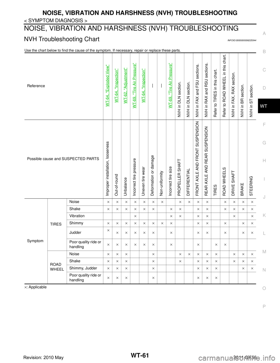
NVH Troubleshooting ChartINFOID:0000000006225544
Use the chart below to find the cause of the symp tom. If necessary, repair or replace these parts.
×: ApplicableReference
WT-64, "
Exploded View
"
WT-64, "
Inspection
"
WT-62, "
Adjustment
"
WT-69, "
Tire Air Pressure
"
WT-64, "
Inspection
"
—
—
WT-69, "
Tire Air Pressure
"
NVH in DLN section.
NVH in DLN section.
NVH in FAX and FSU sections.
NVH in RAX and RSU sections.
Refer to TIRES in this chart.
Refer to ROAD WHEEL in this chart.
NVH in FAX, RAX section.
NVH in BR section.
NVH in ST section.
Possible cause and SUSPECTED PARTS
Improper installation, looseness
Out-of-round
Unbalance
Incorrect tire pressure
Uneven tire wear
Deformation or damage
Non-uniformity
Incorrect tire size
PROPELLER SHAFT
DIFFERENTIAL
FRONT AXLE AND FRONT SUSPENSION
REAR AXLE AND REAR SUSPENSION
TIRES
ROAD WHEELS
DRIVE SHAFT
BRAKE
STEERING
Symptom TIRESNoise
××××××× ×××× ××××
Shake ×××××× ×× ×× ××××
Vibration ×××××××
Shimmy ×××××××× ×× × ××
Judder ×
××××× × ×× × ××
Poor quality ride or
handling ×××××× × × ××
ROAD
WHEEL Noise
××× × ××××× ×××
Shake ××× × × ××× ×××
Shimmy, Judder ××× × ××× ××
Poor quality ride or
handling ××× × ×××
Revision: 2010 May2011 QX56