Page 5191 of 5598
![INFINITI QX56 2011 Factory Service Manual
U1000 CAN COMM CIRCUITTM-103
< DTC/CIRCUIT DIAGNOSIS > [7AT: RE7R01B]
C
EF
G H
I
J
K L
M A
B
TM
N
O P
U1000 CAN COMM CIRCUIT
DescriptionINFOID:0000000006226798
CAN (Controller Area Network) is a seri](/manual-img/42/57033/w960_57033-5190.png "INFINITI QX56 2011 Factory Service Manual
U1000 CAN COMM CIRCUITTM-103
< DTC/CIRCUIT DIAGNOSIS > [7AT: RE7R01B]
C
EF
G H
I
J
K L
M A
B
TM
N
O P
U1000 CAN COMM CIRCUIT
DescriptionINFOID:0000000006226798
CAN (Controller Area Network) is a seri")
U1000 CAN COMM CIRCUITTM-103
< DTC/CIRCUIT DIAGNOSIS > [7AT: RE7R01B]
C
EF
G H
I
J
K L
M A
B
TM
N
O P
U1000 CAN COMM CIRCUIT
DescriptionINFOID:0000000006226798
CAN (Controller Area Network) is a serial communication line for real-time application. It is an on-vehicle mul-
tiplex communication line with high data communica tion speed and excellent malfunction detection ability.
Many electronic control units are equipped onto a vehicl e, and each control unit shares information and links
with other control units during operation (not independently ). In CAN communication, control units are con-
nected with 2 communication lines (CAN-H line, CAN-L li ne) allowing a high rate of information transmission
with less wiring. Each control unit transmits/recei ves data but selectively reads required data only.
DTC LogicINFOID:0000000006226799
DTC DETECTION LOGIC
DTC CONFIRMATION PROCEDURE
1.PRECONDITIONING
If “DTC CONFIRMATION PROCEDURE” is previously c onducted, always turn ignition switch OFF and wait at
least 10 seconds before performing the next test.
>> GO TO 2.
2.CHECK DTC DETECTION
With CONSULT-III
1. Start the engine.
2. Run engine for at least 2 cons ecutive seconds at idle speed.
3. Perform “Self Diagnostic Resu lts” in “TRANSMISSION”.
With GST
Follow the procedure “With CONSULT-III”
Is
“U1000” detected?
YES >> Go to TM-103, "Diagnosis Procedure".
NO >> INSPECTION END
Diagnosis ProcedureINFOID:0000000006226800
Go to LAN-18, "Trouble Diagnosis Flow Chart".
DTC Trouble diagnosis name DTC is detected if... Possible cause
U1000 CAN Communication Line TCM is not transmitting or re-
ceiving CAN communication
signal for 2 seconds or more. Harness or connectors
(CAN communication line is
open or shorted.)
TCM
Revision: 2010 May2011 QX56
Page 5499 of 5598
U1000 CAN COMM CIRCUITWT-49
< DTC/CIRCUIT DIAGNOSIS >
C
DF
G H
I
J
K L
M A
B
WT
N
O P
U1000 CAN COMM CIRCUIT
DescriptionINFOID:0000000006225524
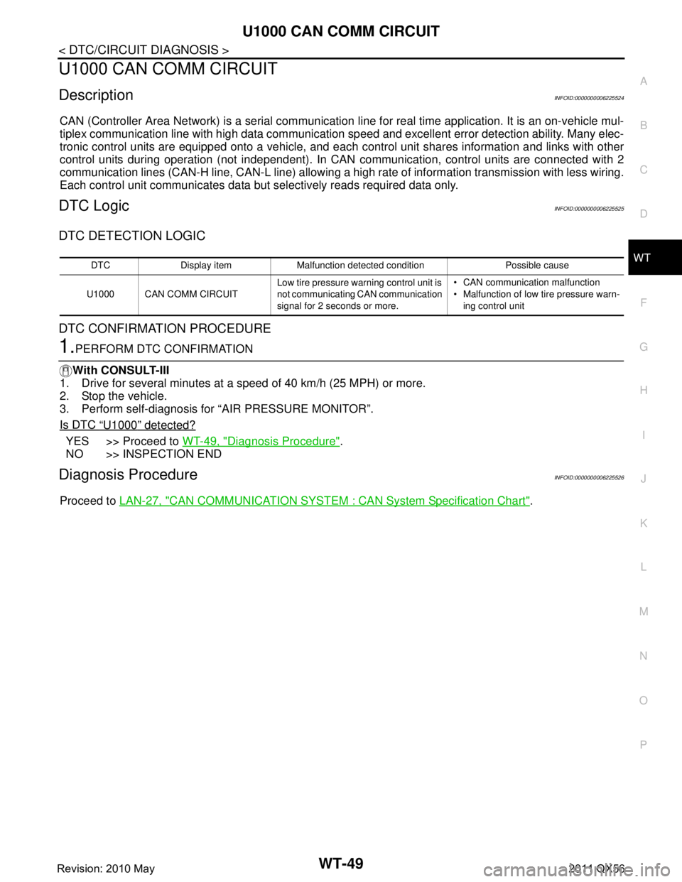
CAN (Controller Area Network) is a serial communication li ne for real time application. It is an on-vehicle mul-
tiplex communication line with high data communication speed and excellent error detection ability. Many elec-
tronic control units are equipped onto a vehicle, and each control unit shares information and links with other
control units during operation (not independent). In CAN communication, control units are connected with 2
communication lines (CAN-H line, CAN-L line) allowing a high rate of information transmission with less wiring.
Each control unit communicates data but selectively reads required data only.
DTC LogicINFOID:0000000006225525
DTC DETECTION LOGIC
DTC CONFIRMATION PROCEDURE
1.PERFORM DTC CONFIRMATION
With CONSULT-III
1. Drive for several minutes at a speed of 40 km/h (25 MPH) or more.
2. Stop the vehicle.
3. Perform self-diagnosis for “AIR PRESSURE MONITOR”.
Is DTC
“U1000” detected?
YES >> Proceed to WT-49, "Diagnosis Procedure".
NO >> INSPECTION END
Diagnosis ProcedureINFOID:0000000006225526
Proceed to LAN-27, "CAN COMMUNICATION SYSTEM : CA N System Specification Chart".
DTC Display item Malfunction detected condition Possible cause
U1000 CAN COMM CIRCUIT Low tire pressure warn
ing control unit is
not communicating CAN communication
signal for 2 seconds or more. CAN communication malfunction
Malfunction of low tire pressure warn-
ing control unit
Revision: 2010 May2011 QX56
Page 5538 of 5598
DIAGNOSIS SYSTEM (IPDM E/R)WW-19
< SYSTEM DESCRIPTION >
C
DE
F
G H
I
J
K
M A
B
WW
N
O P
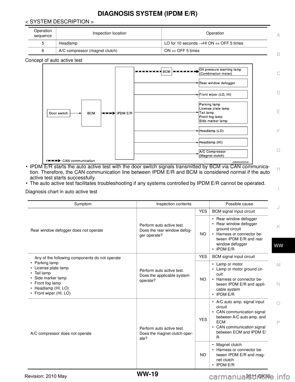
Concept of auto active test
IPDM E/R starts the auto active test with the door
switch signals transmitted by BCM via CAN communica-
tion. Therefore, the CAN communication line between IPDM E/R and BCM is considered normal if the auto
active test starts successfully.
The auto active test facilitates troubleshooting if any systems controlled by IPDM E/R cannot be operated.
Diagnosis chart in auto active test
5 Headlamp LO for 10 seconds →HI ON ⇔ OFF 5 times
6 A/C compressor (magnet clutch) ON ⇔ OFF 5 times
Operation
sequence Inspection location Operation
JMMIA0492GB
Symptom Inspection contents Possible cause
Rear window defogger does not operate Perform auto active test.
Does the rear window defog-
ger operate?YES BCM signal input circuit
NO Rear window defogger
Rear window defogger
ground circuit
Harness or connector be- tween IPDM E/R and rear
window defogger
IPDM E/R
Any of the following components do not operate
Parking lamp
License plate lamp
Tail lamp
Side marker lamp
Front fog lamp
Headlamp (HI, LO)
Front wiper (HI, LO) Perform auto active test.
Does the applicable system
operate?YES BCM signal input circuit
NO Lamp or motor
Lamp or motor ground cir-
cuit
Harness or connector be- tween IPDM E/R and appli-
cable system
IPDM E/R
A/C compressor does not operate Perform auto active test.
Does the magnet clutch oper-
ate?YES
A/C auto amp. signal input
circuit
CAN communication signal
between A/C auto amp. and
ECM
CAN communication signal
between ECM and IPDM E/
R
NO Magnet clutch
Harness or connector be-
tween IPDM E/R and mag-
net clutch
IPDM E/R
Revision: 2010 May2011 QX56