2011 INFINITI QX56 ignition
[x] Cancel search: ignitionPage 1662 of 5598

DLK-126
< DTC/CIRCUIT DIAGNOSIS >
DOOR LOCK ACTUATOR
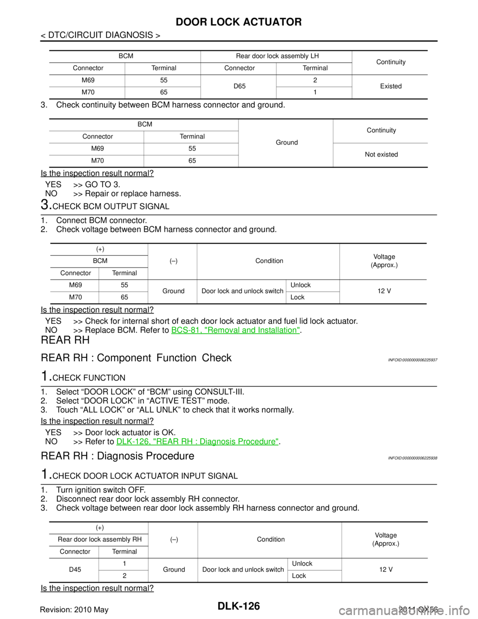
3. Check continuity between BCM harness connector and ground.
Is the inspection result normal?
YES >> GO TO 3.
NO >> Repair or replace harness.
3.CHECK BCM OUTPUT SIGNAL
1. Connect BCM connector.
2. Check voltage between BCM harness connector and ground.
Is the inspection result normal?
YES >> Check for internal short of each door lock actuator and fuel lid lock actuator.
NO >> Replace BCM. Refer to BCS-81, "
Removal and Installation".
REAR RH
REAR RH : Component Function CheckINFOID:0000000006225937
1.CHECK FUNCTION
1. Select “DOOR LOCK” of “BCM” using CONSULT-III.
2. Select “DOOR LOCK” in “ACTIVE TEST” mode.
3. Touch “ALL LOCK” or “ALL UNLK” to check that it works normally.
Is the inspection result normal?
YES >> Door lock actuator is OK.
NO >> Refer to DLK-126, "
REAR RH : Diagnosis Procedure".
REAR RH : Diagnosis ProcedureINFOID:0000000006225938
1.CHECK DOOR LOCK ACTUATOR INPUT SIGNAL
1. Turn ignition switch OFF.
2. Disconnect rear door lock assembly RH connector.
3. Check voltage between rear door lock assembly RH harness connector and ground.
Is the inspection result normal?
BCM Rear door lock assembly LH Continuity
Connector Terminal Connector Terminal
M69 55 D652
Existed
M70 65 1
BCM GroundContinuity
Connector Terminal
M69 55 Not existed
M70 65
(+)
(–) Condition Vo l ta g e
(Approx.)
BCM
Connector Terminal M69 55 Ground Door lock and unlock switch Unlock
12 V
M70 65 Lock
(+)
(–) Condition Vol tag e
(Approx.)
Rear door lock assembly RH
Connector Terminal
D45 1
Ground Door lock and unlock switch Unlock
12 V
2Lock
Revision: 2010 May2011 QX56
Page 1664 of 5598

DLK-128
< DTC/CIRCUIT DIAGNOSIS >
FUEL LID LOCK ACTUATOR
FUEL LID LOCK ACTUATOR
Component Function CheckINFOID:0000000006225939
1.CHECK FUNCTION
1. Select “DOOR LOCK” of “BCM” using CONSULT-III.
2. Select “DOOR LOCK” in “ACTIVE TEST” mode.
3. Touch “ALL LOCK” or “ALL UNLK” to check that it works normally.
Is the inspection result normal?
YES >> Fuel lid lock actuator is OK.
NO >> Refer to DLK-128, "
Diagnosis Procedure".
Diagnosis ProcedureINFOID:0000000006225940
1.CHECK FUEL LID LOCK ACTUATOR INPUT SIGNAL
1. Turn ignition switch OFF.
2. Disconnect fuel lid lock actuator connector.
3. Check voltage between fuel lid lock actuator harness connector and ground.
Is the inspection result normal?
YES >> Replace fuel lid lock actuator.
NO >> GO TO 2.
2.CHECK FUEL LID LOCK ACTUATOR CIRCUIT
1. Disconnect BCM, all door lock actuators connector.
2. Check continuity between BCM harness connector and fuel lid lock actuator harness connector.
3. Check continuity between BCM harness connector and ground.
Is the inspection result normal?
YES >> GO TO 3.
NO >> Repair or replace harness.
3.CHECK BCM OUTPUT SIGNAL
1. Connect BCM connector.
2. Check voltage between BCM harness connector and ground.
(+)
(–) Condition Voltag e
(Approx.)
Fuel lid lock actuator
Connector Terminal
B19 1
Ground Door lock and unlock
switch Unlock
12 V
2Lock
BCM Fuel lid lock actuator Continuity
Connector Terminal Connector Terminal
M70 65
B19 2
Existed
66 1
BCM GroundContinuity
Connector Terminal
M70 65
Not existed
66
Revision: 2010 May2011 QX56
Page 1666 of 5598

DLK-130
< DTC/CIRCUIT DIAGNOSIS >
UNLOCK SENSOR
UNLOCK SENSOR
Component Function CheckINFOID:0000000006225941
1.CHECK FUNCTION
1. Select “INTELLIGE NT KEY” of “BCM” using CONSULT-III.
2. Select “UNLK SEN-DR” in “DATA MONITOR” mode.
3. Check that the function operates normall y according to the following conditions.
Is the inspection result normal?
YES >> Unlock sensor is OK.
NO >> Refer to DLK-130, "
Diagnosis Procedure".
Diagnosis ProcedureINFOID:0000000006225942
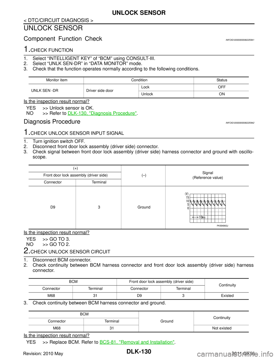
1.CHECK UNLOCK SENSOR INPUT SIGNAL
1. Turn ignition switch OFF.
2. Disconnect front door lock assembly (driver side) connector.
3. Check signal between front door lock assembly (d river side) harness connector and ground with oscillo-
scope.
Is the inspection result normal?
YES >> GO TO 3.
NO >> GO TO 2.
2.CHECK UNLOCK SENSOR CIRCUIT
1. Disconnect BCM connector.
2. Check continuity between BCM harness connector and front door lock assembly (driver side) harness connector.
3. Check continuity between BCM harness connector and ground.
Is the inspection result normal?
YES >> Replace BCM. Refer to BCS-81, "Removal and Installation".
Monitor item Condition Status
UNLK SEN -DR Driver side door Lock OFF
Unlock ON
(+)
(–)Signal
(Reference value)
Front door lock assembly (driver side)
Connector Terminal
D9 3 Ground
PKIB4960J
BCM Front door lock assembly (driver side) Continuity
Connector Terminal Connector Terminal
M68 31 D9 3 Existed
BCM GroundContinuity
Connector Terminal
M68 31 Not existed
Revision: 2010 May2011 QX56
Page 1667 of 5598

UNLOCK SENSORDLK-131
< DTC/CIRCUIT DIAGNOSIS >
C
DE
F
G H
I
J
L
M A
B
DLK
N
O P
NO >> Repair or replace harness.
3.CHECK UNLOCK SENSOR GROUND CIRCUIT
Check continuity between front door lock assembly (driver side) harness connector and ground.
Is the inspection result normal?
YES >> GO TO 4.
NO >> Repair or replace harness.
4.CHECK UNLOCK SENSOR
Refer to DLK-131, "
Component Inspection".
Is the inspection result normal?
YES >> GO TO 5.
NO >> Replace front door lock assembly (driver side).
5.CHECK INTERMITTENT INCIDENT
Refer to GI-40, "
Intermittent Incident".
>> INSPECTION END
Component InspectionINFOID:0000000006225943
1.CHECK UNLOCK SENSOR
1. Turn ignition switch OFF.
2. Disconnect front door lock assembly (driver side) connector.
3. Check continuity between front door lock assembly (driver side) terminals.
Is the inspection result normal?
YES >> INSPECTION END
NO >> Replace front door lock assembly (driver side).
Front door lock assembly (driver side)
GroundContinuity
Connector Terminal
D9 4 Existed
Front door lock assembly (driver side) Condition Continuity
Te r m i n a l
3 4 Driver side door Unlock Existed
Lock Not existed
Revision: 2010 May2011 QX56
Page 1668 of 5598

DLK-132
< DTC/CIRCUIT DIAGNOSIS >
DOOR KEY CYLINDER SWITCH
DOOR KEY CYLINDER SWITCH
Component Function CheckINFOID:0000000006225944
1.CHECK FUNCTION
1. Select “DOOR LOCK” of “BCM” using CONSULT-III.
2. Select “KEY CYL LK-SW”, “KEY CY L UN-SW” in “DATA MONITOR” mode.
3. Check that the function operates normall y according to the following conditions.
Is the inspection result normal?
YES >> Door key cylinder switch is OK.
NO >> Refer to DLK-132, "
Diagnosis Procedure".
Diagnosis ProcedureINFOID:0000000006225945
1.CHECK DOOR KEY CYLINDER SWITCH INPUT SIGNAL
1. Turn ignition switch OFF.
2. Disconnect front door lock assembly (driver side) connector.
3. Check voltage between front door lock assembly (driver side) harness connector and ground.
Is the inspection result normal?
YES >> GO TO 3.
NO >> GO TO 2.
2.CHECK DOOR KEY CYLINDER SWITCH SIGNAL CIRCUIT
1. Disconnect power window main switch connector.
2. Check continuity between power window main s witch harness connector and front door lock assembly
(driver side) harness connector.
3. Check continuity between power window main switch harness connector and ground.
Is the inspection result normal?
YES >> Replace power window main switch. Refer to PWC-74, "Removal and Installation".
Monitor item Condition Status
KEY CYL LK-SW Driver side door key cylinder Lock ON
Neutral / Unlock OFF
KEY CYL UN-SW Unlock ON
Neutral / Lock OFF
(+)
(–)Vo l ta g e
(Approx.)
Front door lock assembly (driver side)
Connector Terminal
D9 5
Ground 5 V
6
Power window main switch Front do or lock assembly (driver side)
Continuity
Connector Terminal Connector Terminal
D5 4
D9 6
Existed
65
Power window main switch GroundContinuity
Connector Terminal
D5 4
Not existed
6
Revision: 2010 May2011 QX56
Page 1669 of 5598

DOOR KEY CYLINDER SWITCHDLK-133
< DTC/CIRCUIT DIAGNOSIS >
C
DE
F
G H
I
J
L
M A
B
DLK
N
O P
NO >> Repair or replace harness.
3.CHECK DOOR KEY CYLINDER SWITCH GROUND CIRCUIT
Check continuity between front door lock assembly (driver side) harness connector and ground.
Is the inspection result normal?
YES >> GO TO 4.
NO >> Repair or replace harness.
4.CHECK DOOR KEY CYLINDER SWITCH
Refer to DLK-133, "
Component Inspection".
Is the inspection result normal?
YES >> GO TO 5.
NO >> Replace front door lock assembly (driver side).
5.CHECK INTERMITTENT INCIDENT
Refer to GI-40, "
Intermittent Incident".
>> INSPECTION END
Component InspectionINFOID:0000000006225946
1.CHECK DOOR KEY CYLINDER SWITCH
1. Turn ignition switch OFF.
2. Disconnect front door lock assembly (driver side) connector.
3. Check continuity between front door lock assembly (driver side) terminals.
Is the inspection result normal?
YES >> INSPECTION END
NO >> Replace front door lock assembly (driver side).
Front door lock assembly (driver side)
GroundContinuity
Connector Terminal
D9 4 Existed
Front door lock assembly (driver side) Condition Continuity
Te r m i n a l
5 4 Driver side door key cylinder Unlock Existed
Neutral / Lock Not existed
6 Lock Existed
Neutral / Unlock Not existed
Revision: 2010 May2011 QX56
Page 1670 of 5598

DLK-134
< DTC/CIRCUIT DIAGNOSIS >
REMOTE KEYLESS ENTRY RECEIVER
REMOTE KEYLESS ENTRY RECEIVER
Component Function CheckINFOID:0000000006225947
1.CHECK FUNCTION
1. Select “INTELLIGE NT KEY” of “BCM” using CONSULT-III.
2. Select “RKE OPE COUN1” in “DATA MONITOR” mode.
3. Check that the function operates normall y according to the following conditions.
Is the inspection result normal?
YES >> Remote keyless entry receiver is OK.
NO >> Refer to DLK-134, "
Diagnosis Procedure".
Diagnosis ProcedureINFOID:0000000006225948
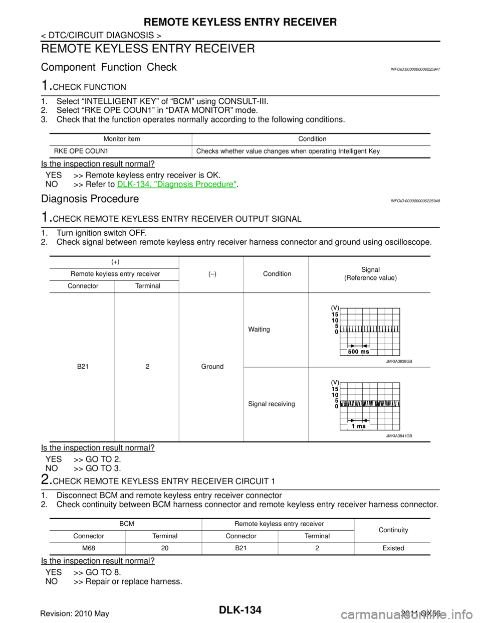
1.CHECK REMOTE KEYLESS ENTRY RECEIVER OUTPUT SIGNAL
1. Turn ignition switch OFF.
2. Check signal between remote keyless entry receiver harness connector and ground using oscilloscope.
Is the inspection result normal?
YES >> GO TO 2.
NO >> GO TO 3.
2.CHECK REMOTE K EYLESS ENTRY RECEIVER CIRCUIT 1
1. Disconnect BCM and remote keyless entry receiver connector
2. Check continuity between BCM harness connector and remote keyless entry receiver harness connector.
Is the inspection result normal?
YES >> GO TO 8.
NO >> Repair or replace harness.
Monitor item Condition
RKE OPE COUN1 Checks whether value changes when operating Intelligent Key
(+) (–) Condition Signal
(Reference value)
Remote keyless entry receiver
Connector Terminal
B21 2 Ground Waiting
Signal receiving
JMKIA3838GB
JMKIA3841GB
BCM Remote keyless entry receiver
Continuity
Connector Terminal Connector Terminal
M68 20 B21 2 Existed
Revision: 2010 May2011 QX56
Page 1673 of 5598

DOOR REQUEST SWITCHDLK-137
< DTC/CIRCUIT DIAGNOSIS >
C
DE
F
G H
I
J
L
M A
B
DLK
N
O P
DOOR REQUEST SWITCH
Component Function CheckINFOID:0000000006225949
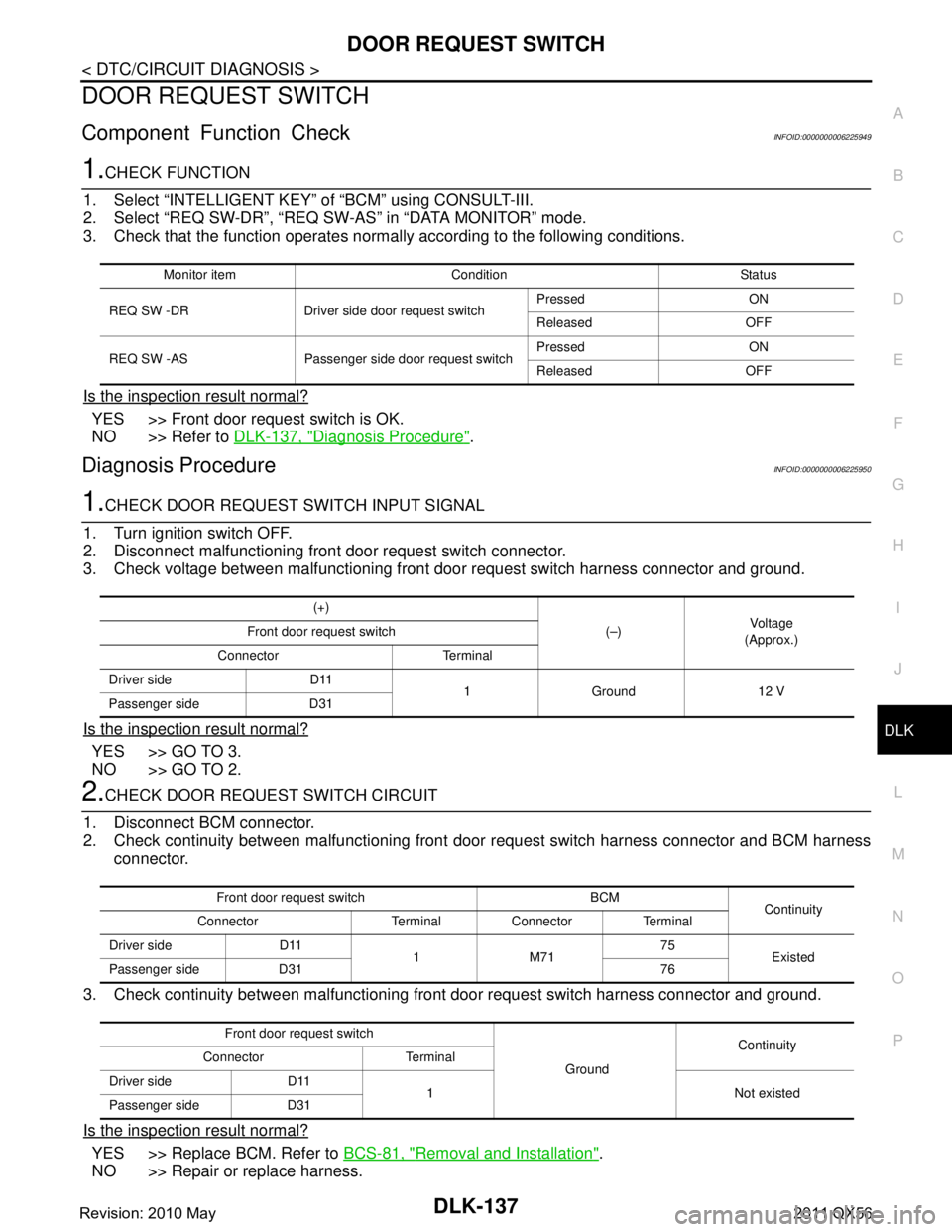
1.CHECK FUNCTION
1. Select “INTELLIGENT KEY” of “BCM” using CONSULT-III.
2. Select “REQ SW-DR”, “REQ SW-AS” in “DATA MONITOR” mode.
3. Check that the function operates normall y according to the following conditions.
Is the inspection result normal?
YES >> Front door request switch is OK.
NO >> Refer to DLK-137, "
Diagnosis Procedure".
Diagnosis ProcedureINFOID:0000000006225950
1.CHECK DOOR REQUEST SWITCH INPUT SIGNAL
1. Turn ignition switch OFF.
2. Disconnect malfunctioning front door request switch connector.
3. Check voltage between malfunctioning front door request switch harness connector and ground.
Is the inspection result normal?
YES >> GO TO 3.
NO >> GO TO 2.
2.CHECK DOOR REQUEST SWITCH CIRCUIT
1. Disconnect BCM connector.
2. Check continuity between malfunctioning front door request switch harness connector and BCM harness
connector.
3. Check continuity between malfunctioning front door request switch harness connector and ground.
Is the inspection result normal?
YES >> Replace BCM. Refer to BCS-81, "Removal and Installation".
NO >> Repair or replace harness.
Monitor item Condition Status
REQ SW -DR Driver side door request switchPressed ON
Released OFF
REQ SW -AS Passenger side door request switch Pressed ON
Released OFF
(+)
(–)Vo l ta g e
(Approx.)
Front door request switch
Connector Terminal
Driver side D11 1 Ground 12 V
Passenger side D31
Front door request switch BCM Continuity
Connector Terminal Connector Terminal
Driver side D11 1M7175
Existed
Passenger side D31 76
Front door request switch GroundContinuity
Connector Terminal
Driver side D11 1 Not existed
Passenger side D31
Revision: 2010 May2011 QX56