2011 INFINITI QX56 coolant level
[x] Cancel search: coolant levelPage 3750 of 5598

MWI
COMPONENT PARTSMWI-7
< SYSTEM DESCRIPTION >
C
DE
F
G H
I
J
K L
M B A
O P
METER SYSTEM : Com ponent DescriptionINFOID:0000000006221691
CLOCK
Unit Description
Combination meter Controls the following with the signals received from each unit via CAN communication and the sig-
nals from switches and sensors.
Speedometer
Tachometer
Engine coolant temperature gauge
Fuel gauge
Engine oil pressure gauge
Voltmeter
Warning lamps
Indicator lamps
Meter illumination control
Meter effect function
Information display
Trip computer switch Transmits the following signals to the combination meter.
Enter switch signal
Select switch signal
Trip reset and illumination con-
trol switch Transmits the following signals to the combination meter.
Trip reset switch signal
Illumination control switch signal (+)
Illumination control switch signal (
−)
ECM Transmits the following signals to the combination meter via CAN communication.
Engine speed signal
Engine coolant temperature signal
Engine status signal
Fuel consumption monitor signal
ABS actuator and electric unit
(control unit) Transmits the vehicle speed signal to the combination meter via CAN communication.
IPDM E/R Transmits the oil pressure switch signal to the BCM via CAN communication.
BCM Transmits the following signals to the combination meter via CAN communication.
Oil pressure switch signal
Position light request signal
Dimmer signal
Door switch signal
Meter ring illumination request signal
Starter relay status signal
TCM Transmits the shift position signal to the combination meter via CAN communication.
A/T shift selector Transmits the following signals to the combination meter.
Manual mode signal
Non-manual mode signal
Manual mode shift up signal
Manual mode shift down signal
Fuel level sensor unit Transmits the fuel level sensor signal to the combination meter.
Oil pressure switch Transmits the oil pressure switch signal to the IPDM E/R.
Ambient sensor Transmits the ambient sensor signal to the combination meter.
A/C auto amp. Transmits the A/C auto amp. connection recognition signal to the combination meter.
Parking brake switch Transmits the parking brake switch signal to the combination meter.
Washer level switch Transmits the washer level switch signal to the combination meter.
Revision: 2010 May2011 QX56
Page 3753 of 5598

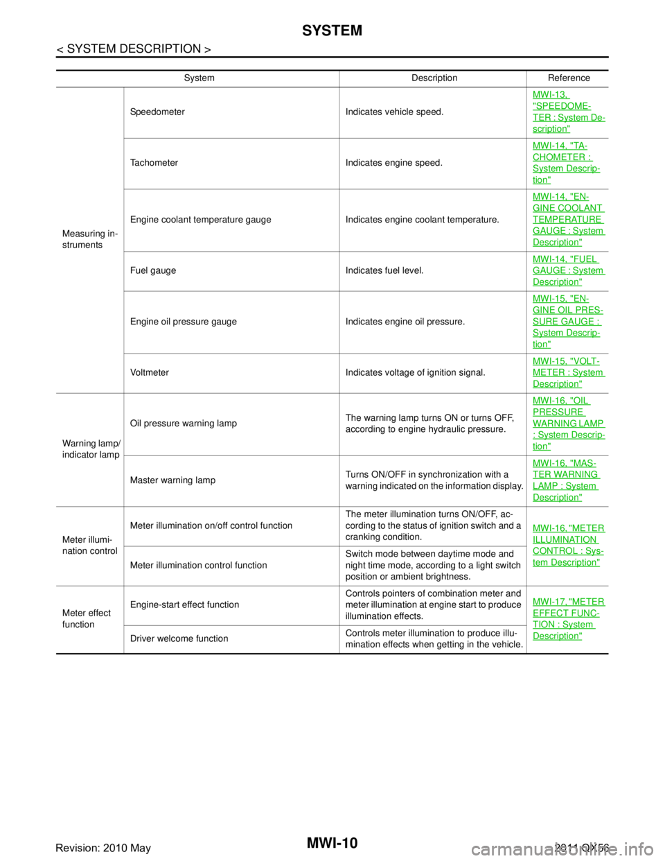
MWI-10
< SYSTEM DESCRIPTION >
SYSTEM
System Description Reference
Measuring in-
struments Speedometer Indicates vehicle speed.
MWI-13,
"SPEEDOME-
TER : System De-
scription"
Tachometer Indicates engine speed.MWI-14, "
TA -
CHOMETER :
System Descrip-
tion"
Engine coolant temperature gauge Indicates engine coolant temperature.MWI-14, "
EN-
GINE COOLANT
TEMPERATURE
GAUGE : System
Description"
Fuel gauge Indicates fuel level.
MWI-14, "
FUEL
GAUGE : System
Description"
Engine oil pressure gauge Indicates engine oil pressure.MWI-15, "
EN-
GINE OIL PRES-
SURE GAUGE :
System Descrip-
tion"
Voltmeter Indicates voltage of ignition signal.
MWI-15, "
VOLT-
METER : System
Description"
Warning lamp/
indicator lampOil pressure warning lamp
The warning lamp turns ON or turns OFF,
according to engine hydraulic pressure.MWI-16, "
OIL
PRESSURE
WARNING LAMP
: System Descrip-
tion"
Master warning lamp
Turns ON/OFF in synchronization with a
warning indicated on the information display.MWI-16, "
MAS-
TER WARNING
LAMP : System
Description"
Meter illumi-
nation controlMeter illumination on/off control function
The meter illumination turns ON/OFF, ac-
cording to the status of ignition switch and a
cranking condition.
MWI-16, "
METER
ILLUMINATION
CONTROL : Sys-
tem Description"Meter illumination control function Switch mode between daytime mode and
night time mode, according to a light switch
position or ambient brightness.
Meter effect
function Engine-start effect function
Controls pointers of combination meter and
meter illumination at engine start to produce
illumination effects.MWI-17, "
METER
EFFECT FUNC-
TION : System
Description"Driver welcome function
Controls meter illumination to produce illu-
mination effects when getting in the vehicle.
Revision: 2010 May2011 QX56
Page 3757 of 5598

MWI-14
< SYSTEM DESCRIPTION >
SYSTEM
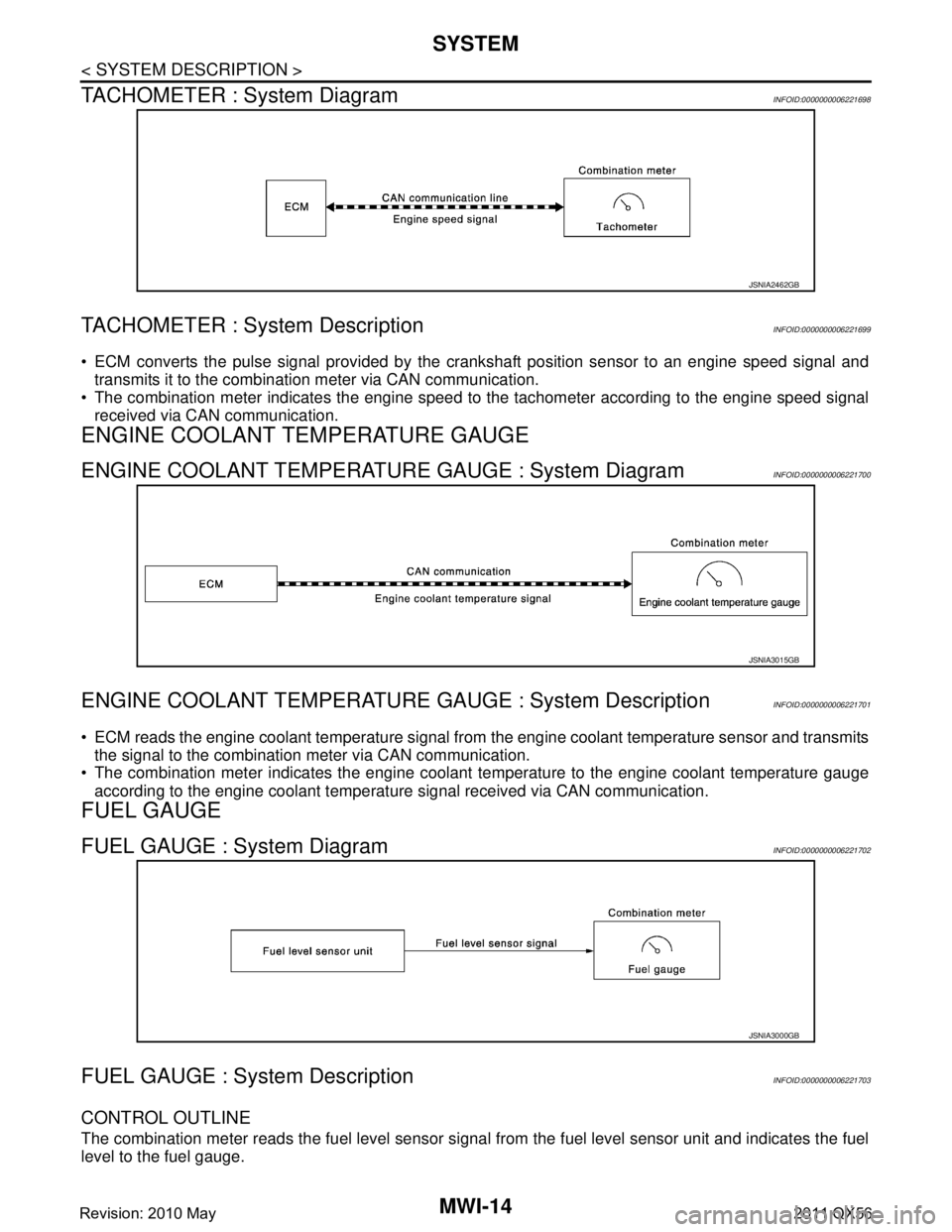
TACHOMETER : System Diagram
INFOID:0000000006221698
TACHOMETER : System DescriptionINFOID:0000000006221699
ECM converts the pulse signal provided by the crankshaft position sensor to an engine speed signal and
transmits it to the combination meter via CAN communication.
The combination meter indicates the engine speed to the tachometer according to the engine speed signal
received via CAN communication.
ENGINE COOLANT TEMPERATURE GAUGE
ENGINE COOLANT TEMPERATURE GAUGE : System DiagramINFOID:0000000006221700
ENGINE COOLANT TEMPERATURE GAUGE : System DescriptionINFOID:0000000006221701
ECM reads the engine coolant temperature signal from the engine coolant temperature sensor and transmits
the signal to the combination meter via CAN communication.
The combination meter indicates the engine coolant temperature to the engine coolant temperature gauge
according to the engine coolant temperature signal received via CAN communication.
FUEL GAUGE
FUEL GAUGE : System DiagramINFOID:0000000006221702
FUEL GAUGE : System DescriptionINFOID:0000000006221703
CONTROL OUTLINE
The combination meter reads the fuel level sensor signal from the fuel level sensor unit and indicates the fuel
level to the fuel gauge.
JSNIA2462GB
JSNIA3015GB
JSNIA3000GB
Revision: 2010 May2011 QX56
Page 3761 of 5598

MWI-18
< SYSTEM DESCRIPTION >
SYSTEM
When recognizing an engine start, the combination meter controls the following items for producing the effect.
Speedometer
Tachometer
Engine coolant temperature gauge
Fuel gauge
Engine oil pressure gauge
Voltmeter
Meter illumination
Meter and Illumination Operations During Engine-start Effect
The combination meter controls the following items during the engine-start effect.
NOTE:
The pointers are stopped and illumination is turned off while cranking the engine.
Engine Start Judgement
The combination meter judges “engine-start” and activates the engine-start effect only once when the follow-
ing operational conditions are all satisfied.
NOTE:
Engine-start effect exits when any of the above operat ional conditions is cancelled during the engine-start
effect.
Signal path
The combination meter judges “engine-start,” according to the following signals and activates the engine-start
effect function.
DRIVER WELCOME FUNCTION
Control item Operation
Speedometer Sweeps the pointer.
Tachometer Sweeps the pointer.
Engine coolant temperature gauge Stops the pointer.
Fuel gauge Stops the pointer.
Engine oil pressure gauge Stops the pointer.
Voltmeter Stops the pointer.
Meter illumination Pointers Turns on the illumination at the effect level.
Information display Turns on the illumination at the normal brightness level.
Other than those above Increases the brightness to the effect level in stages.
Condition
Ignition switch ON position
Vehicle speed Less than 1 km/h (0.6 MPH)
Engine state Other than the time of cranking the engine
500 rpm or more
Information display
(SETTING) The setting of “EFFECT” is “ON.”
Signal name Signal path
Ignition signal —
Starter relay status signal BCM Combination meter
Engine speed signal ECM Combination meter
Engine status signal
Vehicle speed signal ABS actuator and electric unit (control unit) Combination meter
Revision: 2010 May2011 QX56
Page 3774 of 5598
![INFINITI QX56 2011 Factory Service Manual
MWI
DIAGNOSIS SYSTEM (COMBINATION METER)
MWI-31
< SYSTEM DESCRIPTION >
C
D E
F
G H
I
J
K L
M B A
O P
W TEMP METER
[ ° C] XValue of engine coolant temperature signal is received from ECM via CAN com INFINITI QX56 2011 Factory Service Manual
MWI
DIAGNOSIS SYSTEM (COMBINATION METER)
MWI-31
< SYSTEM DESCRIPTION >
C
D E
F
G H
I
J
K L
M B A
O P
W TEMP METER
[ ° C] XValue of engine coolant temperature signal is received from ECM via CAN com](/manual-img/42/57033/w960_57033-3773.png)
MWI
DIAGNOSIS SYSTEM (COMBINATION METER)
MWI-31
< SYSTEM DESCRIPTION >
C
D E
F
G H
I
J
K L
M B A
O P
W TEMP METER
[ ° C] XValue of engine coolant temperature signal is received from ECM via CAN com-
munication.
NOTE:
215 is displayed when the malfunction signal is input.
ABS W/L
[On/Off] Status of ABS warning lamp detected fr
om ABS warning lamp signal is received
from ABS actuator and electric unit (control unit) via CAN communication.
VDC/TCS IND
[On/Off] Status of VDC OFF indicator lamp detected from VDC OFF indicator lamp signal
is received from ABS actuator
and electric unit (control unit) via CAN communica-
tion.
SLIP IND
[On/Off] Status of VDC warning lamp detected from VDC warning lamp signal received
from ABS actuator and electric unit (control unit) via CAN communication.
BRAKE W/L
[On/Off] Status of brake warning lamp detected from brake warning lamp signal is received
from ABS actuator and electric unit (control unit) via CAN communication.
NOTE:
Displays “Off” if the brake warning lamp is illuminated when the valve check starts,
the parking brake switch is turned ON or the brake fluid level switch is turned ON.
DOOR W/L
[On/Off] Status of door open warning detected from door switch signal received from BCM
via CAN communication.
HI-BEAM IND
[On/Off] Status of high beam indicator lamp detected from high beam request signal is re-
ceived from BCM via CAN communication.
TURN IND
[On/Off] Status of turn indicator lamp detected from turn indicator signal is received from
BCM via CAN communication.
FR FOG IND
[Off] This item is displayed, but cannot be monitored.
RR FOG IND
[Off] This item is displayed, but cannot be monitored.
LIGHT IND
[On/Off] Status of light indicator lamp detected from position light request signal is received
from BCM via CAN communication.
OIL W/L
[On/Off] Status of oil pressure warning lamp detected from oil pressure switch signal is re-
ceived from BCM via CAN communication.
MIL
[On/Off] Status of malfunction indicator lamp detected from malfunctioning indicator lamp
signal is received from ECM via CAN communication.
GLOW IND
[Off] This item is displayed, but cannot be monitored.
CRUISE IND
[On/Off] Status of CRUISE indicator detected from ASCD status signal is received from
ECM via CAN communicat ion. (ASCD models)
Status of CRUISE indicator de tected from meter display signal is received from
ADAS control unit via CAN communication. (ICC models)
SET IND
[On/Off] Status of SET indicator detected from meter display signal is received from ADAS
control unit via CAN communication.
CRUISE W/L
[On/Off] Status of CRUISE warning lamp
judged from ICC warning lamp signal received
from ADAS control unit with CAN communication line.
BA W/L
[On/Off] Status of IBA OFF indicator lamp judged from IBA OFF indicator lamp signal re-
ceived from ADAS control unit with CAN communication line.
ATC/T-AMT W/L
[On/Off] Status of A/T CHECK warning lamp judged
from A/T CHECK indicator lamp signal
received from TCM with CAN communication line.
ATF TEMP W/L
[Off] This item is displayed, but cannot be monitored.
4WD W/L
[On/Off] Status of 4WD warning lamp judged from 4WD warning lamp signal received from
4WD control unit with
CAN communication line.
FUEL W/L
[On/Off] Low-fuel warning lamp status detected by the identified fuel level.
WASHER W/L
[On/Off] Status of low washer fluid warning judged from washer level switch input to com-
bination meter.
Display item [Unit]
MAIN
SIGNALS Description
Revision: 2010 May2011 QX56
Page 3778 of 5598

MWI
COMBINATION METERMWI-35
< ECU DIAGNOSIS INFORMATION >
C
DE
F
G H
I
J
K L
M B A
O P
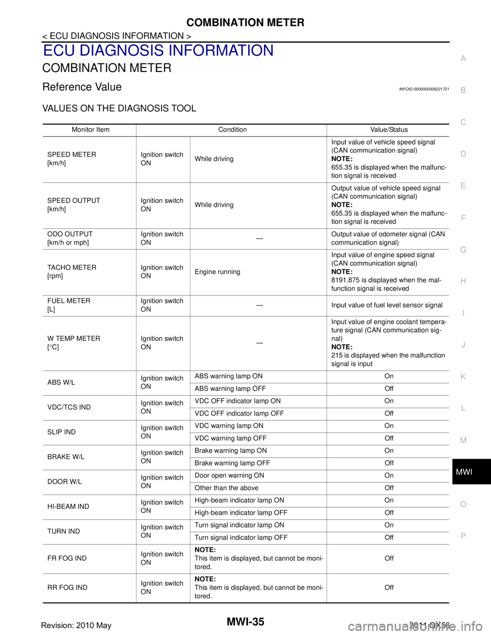
ECU DIAGNOSIS INFORMATION
COMBINATION METER
Reference ValueINFOID:0000000006221721
VALUES ON THE DIAGNOSIS TOOL
Monitor Item Condition Value/Status
SPEED METER
[km/h] Ignition switch
ON
While driving Input value of vehicle speed signal
(CAN communication signal)
NOTE:
655.35 is displayed when the malfunc-
tion signal is received
SPEED OUTPUT
[km/h] Ignition switch
ON
While driving Output value of vehicle speed signal
(CAN communication signal)
NOTE:
655.35 is displayed when the malfunc-
tion signal is received
ODO OUTPUT
[km/h or mph] Ignition switch
ON
—Output value of odometer signal (CAN
communication signal)
TACHO METER
[rpm] Ignition switch
ON
Engine running Input value of engine speed signal
(CAN communication signal)
NOTE:
8191.875 is displayed when the mal-
function signal is received
FUEL METER
[L] Ignition switch
ON
— Input value of fuel level sensor signal
W TEMP METER
[ ° C] Ignition switch
ON
—Input value of engine coolant tempera-
ture signal (CAN communication sig-
nal)
NOTE:
215 is displayed when the malfunction
signal is input
ABS W/L Ignition switch
ONABS warning lamp ON On
ABS warning lamp OFF Off
VDC/TCS IND Ignition switch
ONVDC OFF indicator lamp ON On
VDC OFF indicator lamp OFF Off
SLIP IND Ignition switch
ONVDC warning lamp ON On
VDC warning lamp OFF Off
BRAKE W/L Ignition switch
ONBrake warning lamp ON On
Brake warning lamp OFF Off
DOOR W/L Ignition switch
ONDoor open warning ON On
Other than the above Off
HI-BEAM IND Ignition switch
ONHigh-beam indicator lamp ON On
High-beam indicator lamp OFF Off
TURN IND Ignition switch
ONTurn signal indicator lamp ON On
Turn signal indicator lamp OFF Off
FR FOG IND Ignition switch
ONNOTE:
This item is displayed, but cannot be moni-
tored.
Off
RR FOG IND Ignition switch
ONNOTE:
This item is displayed, but cannot be moni-
tored.
Off
Revision: 2010 May2011 QX56
Page 4261 of 5598

RSU-6
< PERIODIC MAINTENANCE >
WHEEL ALIGNMENT
WHEEL ALIGNMENT
InspectionINFOID:0000000006225661
DESCRIPTION
Measure wheel alignment under unladen conditions.
NOTE:
“Unladen conditions” means that fuel, engine coolant, and lubricant are full. Spare tire, jack, hand tools and
mats are in designated positions.
PRELIMINARY CHECK
Check the following:
Tires for improper air pressure and wear
Road wheels for runout. Refer to WT-64, "
Inspection".
Wheel bearing axial end play. Refer to RAX-5, "
Inspection".
Ball joint axial end play of suspension arm and front lower link. Refer to RSU-20, "
Ball Joint".
Shock absorber operation
Each mounting point of axle and suspension for looseness and deformation
Each of front lower link, rear lower link, rear suspension member, suspension arm and shock absorber for
cracks, deformation, and other damage
Vehicle height (posture)
GENERAL INFORMATION AND RECOMMENDATIONS
A four-wheel thrust alignment should be performed.
- This type of alignment is recomm ended for any NISSAN/INFINITI vehicle.
- The four-wheel “thrust” process helps ensure that t he vehicle is properly aligned and the steering wheel is
centered.
- The alignment rack itself should be capable of accepting any NISSAN/INFINITI vehicle.
- The rack should be checked to ensure that it is level.
Make sure the machine is properly calibrated.
- Your alignment equipment should be regularly calib rated in order to give correct information.
- Check with the manufacturer of your specific equi pment for their recommended Service/Calibration Sched-
ule.
ALIGNMENT PROCESS
IMPORTANT:
Use only the alignment specifications listed in this Service Manual.
When displaying the alignment settings, many alignment machines use “indicators”: (Green/red, plus or
minus, Go/No Go). Never use these indicators.
- The alignment specifications programmed into your machine that operate these indicators may not be cor-
rect.
- This may result in an ERROR.
Some newer alignment machines are equipped with an optional “Rolling Compensation” method to “com- pensate” the sensors (alignment targets or head units). Never use this “Rolling Compensation” method.
- Use the “Jacking Compensation Method”. After installi ng the alignment targets or head units, raise the vehi-
cle and rotate the wheels 1/2 turn both ways.
- See Instructions in the alignment machine you're using for more information on this.
AdjustmentINFOID:0000000006225662
CAMBER
Revision: 2010 May2011 QX56
Page 5418 of 5598

WCS-14
< SYSTEM DESCRIPTION >
DIAGNOSIS SYSTEM (COMBINATION METER)
DIAGNOSIS SYSTEM (COMBINATION METER)
CONSULT-III FunctionINFOID:0000000006222742
CONSULT-III APPLICATION ITEMS
CONSULT-III can perform the following diagnosis modes via CAN communication and the combination meter.
SELF DIAG RESULT
Refer to MWI-43, "DTC Index".
DATA MONITOR
Display Item List
X: Applicable
System Diagnosis mode Description
METER/M&A Self Diagnostic Result The combination meter checks the conditions and displays memorized errors.
Data Monitor Displays the combination meter input/output data in real time.
Special function Lighting history of the warning lamp and indicator lamp can be checked.
Display item [Unit]
MAIN
SIGNALS Description
SPEED METER
[km/h] XValue of vehicle speed
signal received from ABS actuator and el ectric unit (control
unit) via CAN communication.
NOTE:
655.35 is displayed when the malfunction signal is received.
SPEED OUTPUT
[km/h] XVehicle speed signal value transmitted to other units via CAN communication.
NOTE:
655.35 is displayed when the malfunction signal is received.
ODO OUTPUT
[km/h or mph] Odometer signal value transmitted to other units via CAN communication.
TACHO METER
[rpm] XValue of the engine speed signal received from ECM via CAN communication.
NOTE:
8191.875 is displayed when the malfunction signal is received.
FUEL METER
[L] X Fuel level indicated on combination meter.
W TEMP METER
[ ° C] XValue of engine coolant temperature signal is received from ECM via CAN com-
munication.
NOTE:
215 is displayed when the malfunction signal is input.
ABS W/L
[On/Off] Status of ABS warning lamp
detected from ABS warning lamp signal is received
from ABS actuator and electric unit (control unit) via CAN communication.
VDC/TCS IND
[On/Off] Status of VDC OFF indicator lamp detected from VDC OFF indicator lamp signal
is received from ABS actuator and electric
unit (control unit) via CAN communica-
tion.
SLIP IND
[On/Off] Status of VDC warning lamp detected from VDC warning lamp signal received
from ABS actuator and electric unit (control unit) via CAN communication.
BRAKE W/L
[On/Off] Status of brake warning lamp detected from brake warning lamp signal is received
from ABS actuator and electric unit (control unit) via CAN communication.
NOTE:
Displays “Off” if the brake warning lamp is illuminated when the valve check starts,
the parking brake switch is turned ON or the brake fluid level switch is turned ON.
DOOR W/L
[On/Off] Status of door open warning detected from door switch signal received from BCM
via CAN communication.
HI-BEAM IND
[On/Off] Status of high beam indicator lamp detected from high beam request signal is re-
ceived from BCM via CAN communication.
TURN IND
[On/Off] Status of turn indicator lamp detected from turn indicator signal is received from
BCM via CAN communication.
Revision: 2010 May2011 QX56